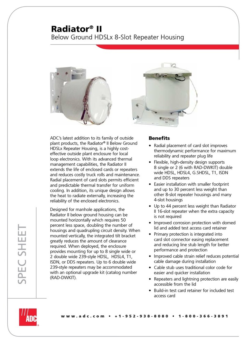
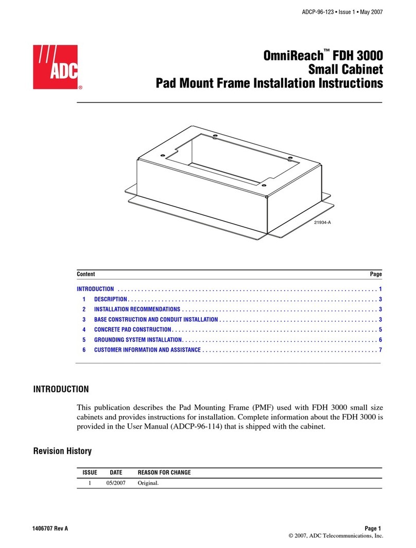
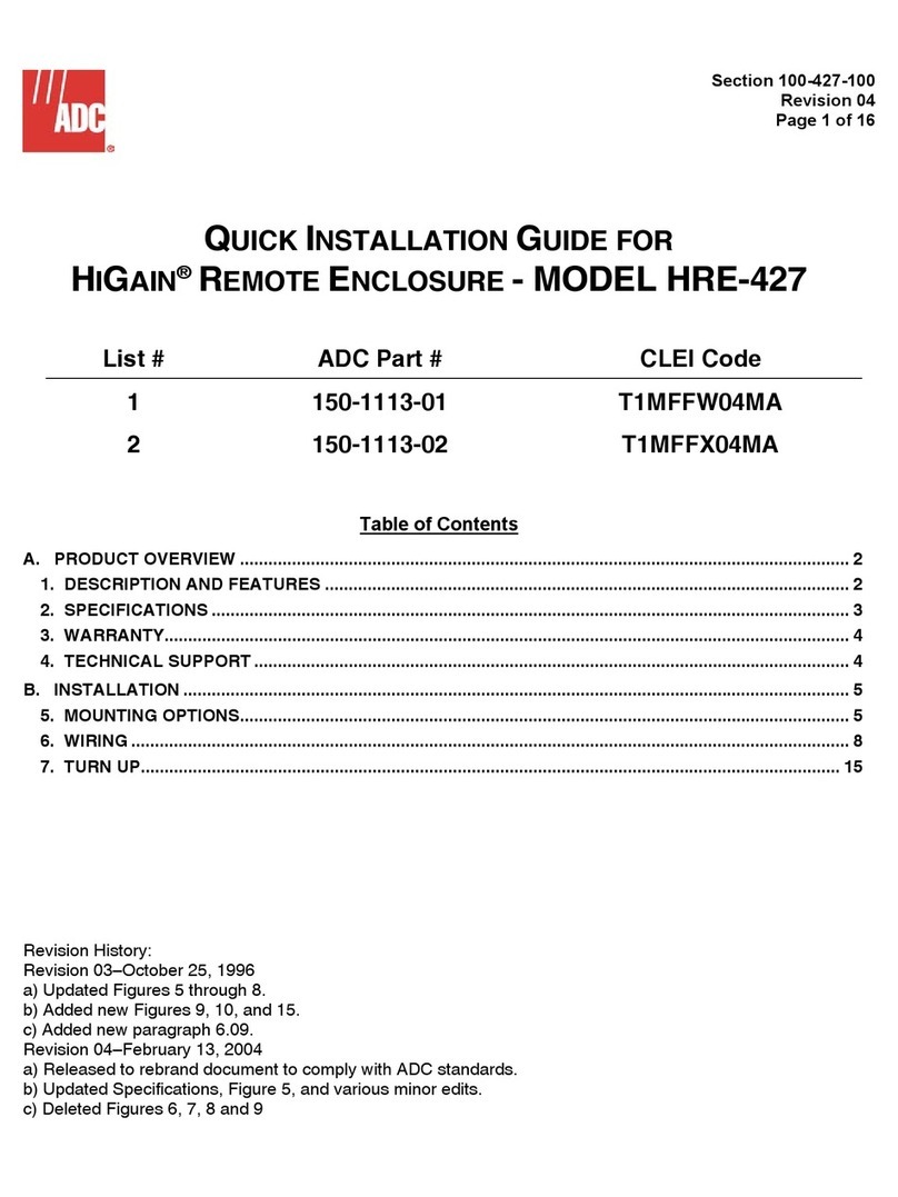
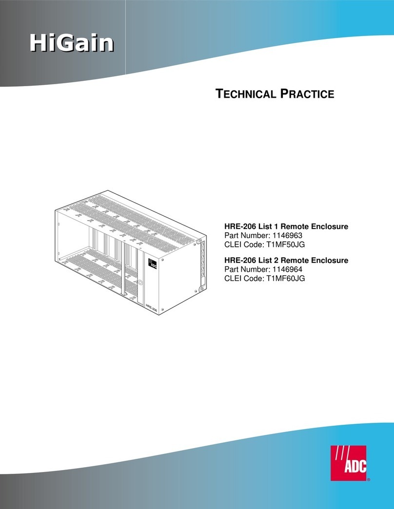
ADC HRE-454 User manual

USER MANUAL
Model List Number Part Number CLEI Code
HRE-454 1A 150-1122-11
HRE-454 2A 150-1122-21 T1RHM2W4
HRE-454 1B 150-1122-12 T1RHMCV4
HRE-454 2B 150-1122-22 T1RHMCW4
HRE-454 3 150-1122-03 N/A
HRE-454 4 150-1122-04 N/A
HRE-454 5 150-1122-05 N/A
HRE-454 6 150-1122-06 N/A
HRE-454 Remote Enclosure

150-454-111-06
ii February 25, 2000 HRE-454
Revision History of This Manual
To order copies of this manual, use document catalog number 150-454-111-06.
Copyright
February 25, 2000
© 2000 ADC DSL Systems, Inc. All rights reserved.
Trademark Information
ADC is a registered trademark of ADC Telecommunications, Inc. HiGain is a registered trademark of ADC DSL Systems, Inc.
No right, license, or interest to such trademarks is granted hereunder, and you agree that no such right, license, or interest
shall be asserted by you with respect to such trademark.
Other product names mentioned in this installation guide are used for identification purposes only and may be trademarks or
registered trademarks of their respective companies.
Disclaimer of Liability
Information contained inthis document is company privateto ADC DSL Systems, Inc., and shall not be modified, used, copied,
reproduced or disclosed in whole or in part without the written consent of ADC.
Contents herein are current as of the date of publication. ADC reserves the right to change the contents without prior notice.
In no event shall ADC be liable for any damages resulting from loss of data, loss of use, or loss of profits, and ADC further
disclaims any and all liability for indirect, incidental, special, consequential or other similar damages. This disclaimer of
liability applies to all products, publications and services during and after the warranty period.
Issue Release Date Revisions Made
04 June 12, 1998 Updated the following:
•HRE-454 List 5 and List 6 Applications section.
•Figure 17, Figure 20, and Table 11.
05 February 25, 2000 •Changed from plastic to all-metal control valves.
•Wired pin 27 to chassis ground.
•Removed optional security cover.
06 August 9, 2002 •ADC rebranding only

150-454-111-06 Using This Manual
HRE-454 February 25, 2000 iii
USING THIS MANUAL
The following conventions are used in this manual:
•Monospace type indicates screen text.
•Keys you press are indicated by small icons such as or . Key combinations to be pressed
simultaneously are indicated with a plus sign as follows: + .
•Items you select are in bold.
•Three types of messages, identified by icons, appear in text.
For a list of abbreviations used in this document, refer to “Appendix D - Glossary” on page 64.
INSPECTING SHIPMENT
Upon receipt of the equipment:
•Unpack each container and inspect the contents for signs of damage. If the equipment has been damaged in
transit, immediately report the extent of damage to the transportation company and to ADC DSL Systems,
Inc. Order replacement equipment, if necessary.
•Check the packing list to ensure complete and accurate shipment of each listed item. If the shipment is short
or irregular, contact ADC DSL Systems, Inc. as described in “Appendix C - Product Support” on page 63. If
you must store the equipment for a prolonged period, store the equipment in its original container.
Notes contain information about special circumstances.
Cautions indicate the possibility of personal injury or equipment damage.
The Electrostatic Discharge (ESD) symbol indicates that a device or assembly is susceptible to
damage from electrostatic discharge.
YENTER
CTRL ESC

Inspecting Shipment 150-454-111-06
iv February 25, 2000 HRE-454

150-454-111-06 Table of Contents
HRE-454 February 25, 2000 v
TABLE OF CONTENTS
Overview ____________________________________________________________________________ 1
Features..............................................................................................................................................1
Applications .......................................................................................................................................1
HRE-454 List 3 and List 4...................................................................................................2
HRE-454 List 5 and List 6...................................................................................................2
Doubler, Line, and Remote Unit .........................................................................................3
Doubler Applications...........................................................................................................4
Functional Description.......................................................................................................................4
Gel-filled Stub Units............................................................................................................4
Air-filled Stub Units............................................................................................................5
Pressurized Applications....................................................................................................................6
Installation___________________________________________________________________________ 8
Unpacking and Inspecting Your Shipment........................................................................................8
Mounting............................................................................................................................................9
Small Pole or Pedestal Mounting ........................................................................................9
Large Pole or Pedestal Mounting ......................................................................................10
Flat Surface Mounting.......................................................................................................11
Rack Mounting ..................................................................................................................12
Grounding ........................................................................................................................................13
Grounding a Pole Mounted Enclosure...............................................................................13
Grounding a Flat Surface Mounted Enclosure ..................................................................15
Slot Chassis Ground Connections....................................................................................................16
Detaching the Dome from the Baseplate .........................................................................................17
Opening the HRE-454 Enclosure.....................................................................................................18
Closing the HRE-454 Enclosure......................................................................................................18
Pivoting the Enclosure.....................................................................................................................19
HiGain Test Card (HTC-400) Installation.......................................................................................19
Circuit Testing...................................................................................................................20
Test Connections ...............................................................................................................21
Test Capabilities ................................................................................................................21
Appendix A - Specifications____________________________________________________________ 23
Appendix B - Technical Reference ______________________________________________________ 24
CLEI Code and P1 Labels................................................................................................................24
HRE-454 Enclosure Information.....................................................................................................25
Stainless Steel Dome .........................................................................................................25
Card Cage ..........................................................................................................................25

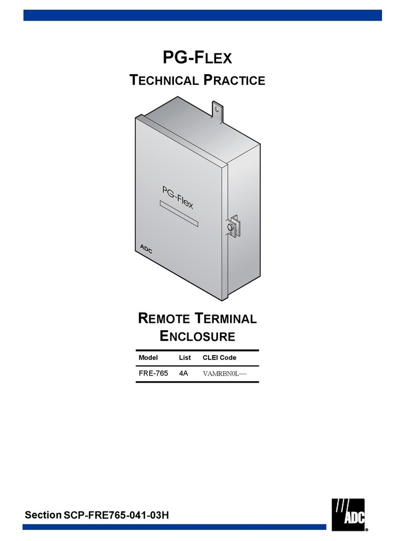
Table of Contents 150-454-111-06
vi February 25, 2000 HRE-454
Lightning Protection Unit (LPU)...................................................................................... 26
Cable Stub and Pressurization........................................................................................... 27
Vented-to-Pressurized Conversion Procedure.................................................................. 28
Spare Connections............................................................................................................. 29
Order Wire Connections ................................................................................................... 29
General Deployment Rules............................................................................................... 29
HRE-454 Wiring ............................................................................................................................. 33
Pinout Information............................................................................................................ 35
Wire List Information ....................................................................................................... 44
HRE-454 Maintenance.................................................................................................................... 53
Splicing ............................................................................................................................. 53
Pre-splicing Procedure...................................................................................................... 53
Splicing Procedure............................................................................................................ 55
Post-splicing Procedure..................................................................................................... 56
Replacement Parts........................................................................................................................... 57
Replacing the Stainless Steel Dome Cover....................................................................... 58
Replacing LPU Arrestor Boards ....................................................................................... 58
Valve Replacement Procedures....................................................................................................... 60
Pressure Relief Valve........................................................................................................ 60
Breather Vent Valve.......................................................................................................... 60
Air Stem Valve..................................................................................................................61
Pressure Cutoff Valve....................................................................................................... 61
Appendix C - Product Support _________________________________________________________ 63
Appendix D - Glossary ________________________________________________________________ 64
Certification and Warranty______________________________________________ Inside Back Cover

150-454-111-06 List of Figures
HRE-454 February 25, 2000 vii
LIST OF FIGURES
1. Typical HRE-454 List 5 and List 6 Application.............................................................................................3
2. HRE-454 Gel-filled Remote Enclosure ..........................................................................................................5
3. HRE-454 Air-filled Remote Enclosure...........................................................................................................6
4. Metal Valves...................................................................................................................................................7
5. HRE-454 Pivot-mounting Bracket..................................................................................................................9
6. Grounding For Pole Mounted Unit...............................................................................................................15
7. Grounding for Flat Surface Mounted Unit....................................................................................................16
8. HRE-454 Enclosure ......................................................................................................................................17
9. HTC-400 List 1 Test Card ............................................................................................................................20
10. HTC-400 Test Card Test Connections..........................................................................................................21
11. HRE-454 Bar Code and P1 Label Locations................................................................................................24
12. HRE-454 with Cover Removed....................................................................................................................26
13. Lightning Protection Unit (LPU)..................................................................................................................27
14. HRE-454 Vertical And Horizontal Mounting Orientation ...........................................................................32
15. HRE-454 Interface Wiring Diagram and Cable Assignment Drawing.........................................................34
16. HRU-412 Pin Assignments...........................................................................................................................35
17. ERU-412 List 2 Pin Assignments.................................................................................................................36
18. HRU-512 Pin Assignments...........................................................................................................................37
19. HRU-612 Pin Assignments...........................................................................................................................38
20. HDU-451, HDU-404, and EDU-451 Pin Assignments ................................................................................39
21. HLU-431 and HLU-432 Pin Assignments Supported by HRE-454 List 5 and List 6..................................40
22. HRU-402 Pin Assignments...........................................................................................................................41
23. H2TU-R-402 Pin Assignments.....................................................................................................................42
24. HRE-454 Wiring Interfaces..........................................................................................................................43
25. Cable Stub Construction ...............................................................................................................................53
26. Dress Splice in Splice Case...........................................................................................................................54
27. Post-splicing Procedure.................................................................................................................................56
28. Screen Folding Diagram ...............................................................................................................................57

List of Tables 150-454-111-06
viii February 25, 2000 HRE-454
LIST OF TABLES
1. Doubler, Line, and Remote Unit Pin Assignment Figure Numbers............................................................... 3
2. Mounting Details............................................................................................................................................ 9
3. Test Connections.......................................................................................................................................... 21
4. HRE-454 Bar Code and P1 Label Information............................................................................................ 24
5. HRE-454 Deployment Rules for Doublers and Remote Units..................................................................... 30
6. HRE-454 Deployment Rules for HLU-431/ 432 Applications vs. Type of Doubler Used.......................... 31
7. HRE-454 28-pair Cable Stub Wire Pair Assignment for Doubler and Remote Units ................................. 33
8. HRE-454, HRU-412, and HRU-402 Wire List............................................................................................ 44
9. HRE-454 and ERU-412 List 2 Wire List..................................................................................................... 46
10. HRE-454 (HRU-512, HRU-612, and H2TU-R-402) Wire List................................................................... 47
11. HRE-454 (HDU-451, HDU-404, and EDU-451) Wire List......................................................................... 49
12. HRE-454 List 5 and List 6 (HLU-431 and HLU-432) Wire List................................................................. 51
13. Replacement Part Kits.................................................................................................................................. 59

150-454-111-06 Overview
HRE-454 February 25, 2000 1
OVERVIEW
This document describes the ADC®HiGain®weatherproof enclosures HRE-454 List 1A, List 1B, List 3 and List
5 (gel-filled), and the HRE-454 List 2A, List 2B, List 4, and List 6 (air-filled). Information on installing these
enclosures is also included. The HRE-454 is part of a HiGain system and used to house the HiGain remote line or
doubler units.
FEATURES
The following features are included on the HRE-454 HiGain weatherproof enclosures:
•Four single-width slots
•30-foot (9.144 M) gel- or air-filled 28-pair cable stub
•100-foot gel- or air-filled 28-pair cable stub (List 1B and List 2B only)
•Flat surface, rack, or pole mount
•Primary surge protection
•Seamless stainless steel cover
•Single stub access
•Tilt forward mounting
APPLICATIONS
The primary application of the HRE-454remote enclosure is to house HiGain remote or doubler units in a HiGain
repeaterlessT1 transmissionsystem. TheHRE-454is anoutdoorenclosure with foursingle-width400mechanical
slots. It has a single gel-filled stub (List 1A, List 1B, List 3, and List 5) or air-filled stub (List 2A, List 2B, List 4,
and List 6).
The air-filled unit can be pressurized locally or from the main feeder cable through an air core stub. This air core
stub protects the air-filled unit from flooding with water when it is mounted in underground manholes. The
gel-filled unit is intended for above ground pole mounting applications.
Figure 2 on page 5 shows the gel-filled HRE-454 and Figure 3 on page 6 shows the air-filled HRE-454. The
gel-filled version comes with a combination air stem/air intake T-valve while the air-filled version comes with an
air stem. The T-valve provides the option of pressurizing the gel-filled unit locally. Another noticeable difference
is that, in the gel-filled unit, the pressure relief valve is replaced by a breather vent valve. However, both units
have primary gas tube surge protection on all signal ports.
For a front and rear view of the internal portion of the HRE-454, see Figure 12 on page 26. The interior four-slot
card cage is also shown. Remote or doubler units are installed in these slots.

Overview 150-454-111-06
2 February 25, 2000 HRE-454
HRE-454 List 3 and List 4
The number of spare pairs in the enclosure has been reduced from eleven to four. The reduction was implemented
to reduce the antenna effect which produces excessive Electromagnetic Interference (EMI) when too many spare
pairs are installed in one enclosure. The four remaining spare pairs are:
•Group 1
–Red and Slate
–Black and Blue
–Black and Orange
•Group 2
–Red and Brown
The four remaining spare pairs and all signal pairs are routed through ferrite coils. The coils are embedded in the
bottom of the enclosure and prevent EMI energy from escaping the pairs. In addition, the green ground wire that
previously connected the stub shield to the enclosure card cage (List 2A) has been replaced by a short copper
braidedwire (see Figure 12on page 26 for more information).The braided wire helpsto reducethe high frequency
noise in the ground plane.
The HRE-454 List 3 and List 4 enclosures have been modified to comply with the following European Union
Conformité Européene (CE) Mark requirements:
•EMI compliance: EN 55022, Class B and IEC-950
•Electrostatic Discharge (ESD) compliance and fast transients: ENC 5082-1, IEC-801-2, and 801-4
•Safety: EN 60950 and IEC 950
HRE-454 List 5 and List 6
The HRE-454 List 5 and List 6 are mainly used for housing HLU-431and HLU-432 line units. The line units have
the same 400/200 mechanics as the doubler and remote units and are used for extending T1 services over
distribution pairs that connect fiber-fed hubs to remote locations. However, instead of being line-powered over
the HDSL pairs, like doubler and remote units, the HLU-431 or HLU-432 is powered from -48 Vdc at its edge
connector onpins 17 (+) and 35 (-).The HRE-454 List 5 and List 6 are located adjacent to the hub and gain access
to the T1 payloads and -48 Vdc power over the cable stub that connects the two units. The system alarm relay
contacts from each of the four slots are also brought out through the stub. See Table 12 on page 51 and Figure 24
on page 43 for wiring information.
Figure 1 on page 3 shows a typical HRE-454 List 5 application where it is used to extend T1 service from a
Nortel© DMS-1 Urban S100E Digital Loop Carrier (DLC) fiber-fed hub to a remote Nortel Access Node. Nortel
provides a HiGain compatible remoteunit that has been integrated into the Access Node shelf precluding the need
for an externally located remote unit.

150-454-111-06 Overview
HRE-454 February 25, 2000 3
Figure 1. Typical HRE-454 List 5 and List 6 Application
Doubler, Line, and Remote Unit
All HRE-454 list numbers use the following doubler, line, and remote units. See the respective figure number
listed in the table next to the unit to view pinout assignments for that unit. Refer to “HRE-454 Wiring” on page 33
for HiGain pair assignments and Figure 24 on page 43 for a diagram listing all the HRE-454 wiring interfaces.
Table 1. Doubler, Line, and Remote Unit Pin Assignment Figure Numbers
Unit Figure and Page
Number Description Wire List
HRU-412 Figure 16 on page 35 Remote module for 2 pair (HDSL), T1 (1.544 Mbps)
service. Table 8 on page 44
ERU-412 List 2 Figure 17 on page 36 Remote module for 2 pair (HDSL), E1 (2.048 Mbps)
service, G.703, 120Ωbalanced. Table 9 on page 46
HRU-512 Figure 18 on page 37 Remote module for 1 pair (HDSL), T1 fractional (128 to 786
kbps) service. Table 10 on page 47
HRU-612 Figure 19 on page 38 Remote module for 1 pair (HDSL), T1 (1.544 Mbps)
service. Table 10 on page 47
HDU-451,
HDU-404, and
EDU-451
Figure 20 on page 39 Doubler module for 2pair (HDSL), T1(HDU-451,HDU-404)
or E1 (EDU-451) service. Table 11 on page 49
HLU-431 List 1D,
HLU-432 Figure 21 on page 40 Line Unit Module for 2 pair (HDSL) T1 (1.546 Mbps)
service. Table 12 on page 51
HRU-402 Figure 22 on page 41 Remote unit for 2 pair (HDSL), T1 (1.544 Mbps) service. Table 8 on page 44
H2TU-R-402 Figure 23 on page 42 Remote unit for 1 pair (HDSL2), T1 (1.544 Mbps) service. Table 10 on page 47
Only the HRE-454 List 5 and List 6 units are wired to provide -48 Vdc power to their four slots.

Overview 150-454-111-06
4 February 25, 2000 HRE-454
Doubler Applications
The HRE-454 houses the following HiGain doubler units:
•HDU-404 T1 (1.544 Mbps)
•HDU-451 T1 (1.544 Mbps)
•EDU-451 E1 (2.048 Mbps)
All three units have identical pin assignments as shown in Figure 20 on page 39. The wire list for each doubler
appears in Table 11 on page 49. Figure 24 on page 43 summarizes all the HRE-454 interfaces.
FUNCTIONAL DESCRIPTION
The following section discusses the function of each component on the HRE-454.
The HRE-454 consists of a metal alloy card cage with space for up to four remote or doubler units, a stainless steel
composite baseplate, and a stainless steel cover which maintains weather-tight integrity. Figure 2 on page 5 and
Figure 3 on page 6 show the details for each unit.
Gel-filled Stub Units
The gel-filled unit comes equipped with three metal valves installed in the base section, as shown in Figure 2 on
page 5. The gel-filled, screened, 28-pair, 24 American Wire Gauge (AWG) cable stub on the gel-filled unit is
equivalent to an ALP FTS-PIC filled core telephone cable. (Refer to Table 7 on page 33for a complete description
of the cable stub.) The unit has foam skin insulation with a single-filled jacket. This insulation allows the cable
stub on the gel-filled unit to be used in buried, aerial, and duct applications. Standard color codes are used for pair
identification with color compounds chosen for electrical balance and permanency. The outer jacket provides a
flexible protective covering that withstands exposure to sunlight, atmospheric temperatures, ground chemicals,
and stresses expected in standard installations. The outside diameter of the cable is 0.64 inches (16.25 mm).
The gel-filled unit is similar to the air-filled unit (Figure 3 on page 6), except that the gel-filled unit has a breather
vent valve instead of a pressure relief valve. The breather vent valve allows the circulation of outside air through
the gel-filled enclosure. Circulating outside air through the gel-filled enclosure prevents the buildup of excessive
moisture and other damaging contaminants within the enclosure.
A combined Schrader air stem/external air input T-valve is also included with the gel units. The Schrader air stem
valve can be used to connect to an external air source or to release the internal pressure whenever the dome is to
be removed. Opposite the Schrader valve, the external air input valve accepts tubing for connection to an external
air source. The pressure cutoff valve allows the external source of air to be cut off when the dome is to be opened.
An optional pressure relief valve is included in the shipping kit for the gel units. The kit comes in a small plastic
bag that is attached to the shrink tab on one of the spare pairs. Use the valve in place of the breather vent valve
when the get unit is to be locally pressurized.
The cable complies with the requirements of the American National Standards Institute
(ANSI) and the Insulated Cable Engineers Association (ICEA) S-84-608-1994 and REA
PE-89, respectively.

150-454-111-06 Overview
HRE-454 February 25, 2000 5
Figure 2. HRE-454 Gel-filled Remote Enclosure
Air-filled Stub Units
The air-filled, screened, 28-pair, 24 AWG cable stub on the air-filled unit (Figure 3 on page 6) is equivalent to an
ALP FTS-PIC air-filled telephone cable. The unit comes with three metal valves: an air-pressure cutoff valve, a
Schrader air stem valve, and a pressure relief valve. The air cutoff valve is used to shut off the inlet air supply that
is pumped from the main feeder cable through the 30-foot (9.144 M) stub into the HRE-454 enclosure. The cable
stub is intended for buried, aerial, and duct applications. Standard color codes are used for pair identification. A
jacket protects the core and provides improved mechanical and electrical characteristics. The outer jacket provides
a flexible protective covering that withstands exposure to sunlight, atmospheric temperatures, ground chemicals,
and stresses expected in standard installations. The outside diameter of the cable is 0.64inches (16.25 mm). Refer
to Table 7 on page 33 for a complete description of the cable stub.
The HRE-454 cable sealing, O-ring, and V-Band seal have been safety tested to 36 pounds per square inch (PSI).
Most cables become ruptured or damaged at this pressure level. However, the HRE-454 cable sealing is designed
to handle this amount of pressure.
The common pressure supplied through the cable is approximately 9 PSI. This is sufficient to prevent water from
entering the cable or housing. ADC recommends pressurizing the enclosure to a maximum of 12 PSI.
The cable complies with the requirements of ANSI/ICEA S-85-625-1996 and REA PE-22.
Avoid using pressures above 36 PSI. Such pressures could force the V-Band away from the
flange and,in effect, impel the dome away from the housing. This could cause damageor injury.

Overview 150-454-111-06
6 February 25, 2000 HRE-454
PRESSURIZED APPLICATIONS
For pressurized applications on the HRE-454, the Schrader air stem valve is used. A pressure gauge is attached to
the valve for the purpose of measuring the internal pressure of the enclosure. This valve is also used to relieve the
internal pressure prior to opening and removing the dome cover. This can be done by depressing the center pin on
the valve (see Figure 3 on page 6 and Figure 4 on page 7 for air stem valve and pin locations).
Figure 3. HRE-454 Air-filled Remote Enclosure
A breather vent valve is enclosed in an air-filled shipping kit. The kit is a small plastic bag attached to a red and
brown colored spare pairs shrink tube. The breather vent valve replaces the pressure relief valve if the air-filled
unit is not pressurized. The assembly allows the enclosure to breathe and keeps the internal atmosphere free of
harmful contaminants. The five metal valves are shown in Figure 4.
To avoid pressure buildup, the pressure relief valve is set to release air at a maximum pressure
of 15 PSI. Due to manufacturing tolerances of the springs, this maximum pressure has a
tolerance of +/- 3 PSI. This pressure and tolerance is well within the safety concerns that may
apply to the housing, personnel, or cable.
The pressure relief valve is not intended for controlling the air pressure that is being applied to
the housing cable.
Depressurizing must be performed every time the cover is removed from the List 2A, List 2B,
List 4, and List 6 equipment. Failure to do so may cause personal injury or damage to the
equipment. This also applies to a gel-filled unit that is being locally pressurized.

150-454-111-06 Overview
HRE-454 February 25, 2000 7
Figure 4. Metal Valves
Unlike the gel-filled unit, the pressure cutoff valve in the air-filled unit cannot be used to cut off
an external air source that is applied to the Schrader air stem valve. The air-filled unit pressure
cutoff valve can only control the air source that is applied to the enclosure through the air core
stub.

Installation 150-454-111-06
8 February 25, 2000 HRE-454
INSTALLATION
UNPACKING AND INSPECTING YOUR SHIPMENT
When you receive the equipment, inspect it for signs of damage. If damage has occurred, immediately report the
extent of damage to the transportation company and to ADC Telecommunications, Inc. (see “Appendix C -
Product Support” on page 63 for more information).
Your shipment should consist of:
•One HRE-454
•One HTC-400 test card
•HiGain Remote Enclosure HRE-454 List 1A, List 2A, List 1B, List 2B, List 3, List 4, List 5, and List 6
Technical Practice
Before installing the HRE-454, unpack and inspect it for missing components and physical damage that may have
occurred during shipping. To unpack the enclosure:
1Remove the HRE-454 from its shipping carton.
2Perform an inventory to verify that all equipment listed on the packing list is present.
3Inspect the enclosure for shipping damage.
4Check the card cage for any sign of breakage.
5Check the O-ring for any sign of damage.
6Find and loosen the retaining screws at the rear base of the card cage.
7Tilt the card cage on its hinge.
8Lower the card cage to its level position and tighten the screws to lock it in position. ADC recommends
always keeping the card cage in a level, locked position.
9Report any damage to the carrier immediately.
If you must store the equipment for a prolonged period of time, store it in the container shipped
with your equipment.
An HTC-400 test card is included with every HRE-454. This unit is found in a separate box inside
the HRE-454 shipping carton. The test card provides an easy-to-use way of accessing and
testing the four cable pairs connected to every HRE-454 slot. The test card is provided free of
charge for your convenience.

150-454-111-06 Installation
HRE-454 February 25, 2000 9
MOUNTING
The HRE-454 may be mounted on a pole, a pedestal, a flat surface, or in a rack (Figure 5). Various methods for
mounting the HRE-454 are detailed in the following sections. The mounting details for the various methods are
as follows:
Figure 5. HRE-454 Pivot-mounting Bracket
Small Pole or Pedestal Mounting
Use the procedure below to mount the enclosure on a pole or pedestal where the pole is less than 7 inches (17.78
cm) in diameter. The overall enclosure dimensions are shown in Figure 8 onpage 17. For details on mounting the
pivot bracket, refer to Figure 5.
Have the following equipment ready before you begin:
•Two 3/8-inch (0.952 cm) lug bolts, 4 inches (10.16 cm) long (minimum)
Table 2. Mounting Details
Mounting Page
Pole mounting with a pole diameter of less than 7 inches (17.78 cm) 9
Pole mounting with a pole diameter greater than 7 inches (17.78 cm) 10
Flat surface mounting 11
Rack mounting 12
Mounting bracket
Base mounting bracket
Pivot slots
Pivot slots

Installation 150-454-111-06
10 February 25, 2000 HRE-454
•Two 3/8-inch (0.952 cm) washers
•One wrench
•One drill with a 1/4-inch (0.635 cm) bit
1Select a convenient mounting location on the pole or pedestal.
2Remove the enclosure base mounting bracket from the mounting bracket by removing the four bolts that
connect each side plate (see Figure 5 on page 9).
3Position the mounting bracket against the pole or pedestal (stub down) and mark the location of the center
mounting lug bolt holes. Use the two middle mounting holes for this application.
4Place the mounting bracket out-of-the-way.
5Drill two 1/4-inch (0.635 cm) diameter holes 3-inches (7.62 cm) deep at the locations marked in Step 3.
6Start a lug bolt in the top center mounting hole and screw the bolt into the pole or pedestal approximately
two-thirds of an inch of its length.
7Insert a lug bolt into the center bottom hole of the mounting bracket and screw the bolt into the bottom
mounting hole.
8Secure the enclosure bracket to the pole or pedestal by tightening the lug bolts.
9Reattach the enclosure to the mounting bracket and torque the mounting bracket bolts between 30 and 40
inch-pounds.
10 If the cable stub connectsto an underground cable, dress the cable down the pole or pedestal to thesplice case.
If the cable stub connects to an aerial cable, form a drip loop in the cable and dress it up the pole or pedestal
to the splice case.
Large Pole or Pedestal Mounting
Use the procedure below to mount the enclosure ona pole or pedestal where the pole is greater than7 inches (17.78
cm) in diameter. The overall enclosure dimensions are shown in Figure 8 on page 17. Figure 5 on page 9 details
the mounting pivot bracket. Have the following equipment ready before you begin:
•Four 3/8-inch (0.952 cm) lug bolts, 4 inches (10.16 cm) long (minimum)
•Four 3/8-inch (0.952 cm) washers
•One wrench
•One pencil
•One drill with a 1/4-inch (0.635 cm) bit
Because of the weight and size of the enclosure, you may want to remove the dome before
mounting. The enclosure may be mounted horizontally, vertically, or any orientation desired. A
vertical orientation is preferred because it reduces the thermal stress on the installed plugs. A
shady location is also preferred for the same reason. Refer to Table 5 on page 30 and Table 6
on page 31 for temperature specifications.
While mounting the enclosure, hold the enclosure securely to prevent personal injury or
damage to the enclosure.

150-454-111-06 Installation
HRE-454 February 25, 2000 11
1Select a convenient mounting location on the pole or pedestal.
2Unscrew the four bolts that connect the mounting bracket side plates to the enclosure base. Remove the
mounting bracket from the enclosure.
3Position the mounting bracket against the pole or pedestal (stub down) and mark the location of the four
mounting holes. Use the four corner mounting holes for this application.
4Place the mounting bracket out-of-the-way.
5Drill four holes 1/4-inch (0.635 cm) in diameter by 3 inches (7.62 cm) deep at the locations marked in Step 3.
6Start an anchor bolt in each of the two top matched bolt mounting slots and tighten the bolts into the wall
approximately two-thirds of an inch of the bolt length.
7Rest the mounting bracket top outside holes over the two bolts.
8Insert the lug bolts into the two bottom outside holes of the mounting bracket and start bolts.
9Secure the enclosure bracket to the pole or pedestal by tightening all lug bolts until snug.
10 Using the four sideplate bolts, reattach the enclosure’s base mounting bracket to the mounting bracket.
Torque the mounting bracket bolts between 30 and 40 inch-pounds.
11 If the cable stub connects to an underground cable, dress the cable stub down the pole or pedestal to the splice
case. If the cable stub connects to an aerial cable, form a drip loop in the stub and dress the stub up the pole
or pedestal to the splice case.
Flat Surface Mounting
Use the procedure below to mount the enclosure on a flat surface in a manhole. You must allow for enough top
clearance to remove the cover (see Figure 8 on page 17). Allow at least 3 inches (7.62 cm) of clearance above the
dome if the 31° tilt feature is used and allow at least 10 inches (25.4 cm) of clearance if the tilt feature is not used.
Have the following equipment ready before you begin:
•Four 3/8-inch (0.952 cm), 16 NC anchor bolts, 21/2inches (6.35 cm) long for wall mounting
•Four 3/8-inch (0.952 cm) washers
•One Wrench
•One Drill with a 1/4-inch (0.635 cm) bit
While mounting the enclosure, hold the enclosure securely to prevent personal injury or
damage to the enclosure.
The desiccant bags shipped with the List 2A, List 2B, List 4, and List 6 units must be activated
prior to closing the lid. Do this by removing the bags from their plastic container and placing
them inside the enclosure.
While mounting the enclosure, hold it securely to prevent personal injury or damage.

Installation 150-454-111-06
12 February 25, 2000 HRE-454
To mount the enclosure on a flat surface:
1Select a convenient mounting location on a wall.
2Remove the enclosure base mounting bracket from the mounting bracket by removing the four bolts that
connect each side plate (see Figure 5 on page 9).
3Position the mountingbracket against the wall and markthe location of the four outsidemounting holes. Place
the mounting bracket out-of-the-way.
4Drill four 1/4-inch (0.635 cm) diameter holes 21/2-inches (6.35 cm) deep at the locations marked in Step 3.
5Start an anchor bolt in each of the two top matched bolt mounting slots and tighten the bolts into the wall
approximately two-thirds of an inch of the bolt length.
6Insert the anchor bolts into the two bottom holes located on the outside of the mounting bracket and tighten
the bolts into the bottom two holes of the mounting bracket.
7Secure the enclosure bracket to the wall by tightening all anchor bolts.
8Reattach the enclosure base mounting brackets to the mounting bracket with the four sideplate bolts and
torque the mounting bracket bolts between 30 and 40 inch-pounds.
9If the cable stub connects to an underground cable, dress the cable down the wall to the splice case. If the
cable stub connects to an aerial cable, form a drip loop in the cable and dress it up the wall to the splice case.
Rack Mounting
Use the procedure below when mounting the enclosure in a rack. Have the following equipment ready before you
begin:
•Four 3/8-inch thru-bolts for rack mounting
•Four 3/8-inch nonmetallic washers. Nonmetallic washers are required to avoid a ground loop that may result
if both the rack and the enclosure are grounded. ADC does not recommend using the rack ground for the
enclosure ground since its integrity is not one-hundred percent reliable.
•One wrench
1Select a convenient location on the cable rack.
2Position the enclosure so that the outside slots and holes in the mounting bracket align with the mounting
holes in the cable rack.
Because of the weight and size of the enclosure, you may want to remove the dome before
mounting the enclosure. The enclosure must be mounted vertically. A shady location is also
preferred to minimize thermal stress. Refer to Table 5 on page 30 and Table 6 on page 31 for
thermal load capacity information.
While mounting the enclosure, hold it securely to prevent personal injury or damage to the
enclosure.
This manual suits for next models
8
Table of contents
Other ADC Enclosure manuals

ADC
ADC HiGain HRE-427 User manual

ADC
ADC HIGAIN HRE-712 List 1 User manual

ADC
ADC HiGain HRE-819 User manual

ADC
ADC Fiber Optic Wall Box FL1000 Series Operating and safety instructions

ADC
ADC HiGain HRE-500 List 1 User manual

ADC
ADC HiGain HRE-450 List 4A User manual

ADC
ADC OmniReach FDH 3000 User manual

ADC
ADC FRE-765 User manual

ADC
ADC HiGain HRE-504 User manual

ADC
ADC HiGain HRE-450 List 4A User manual