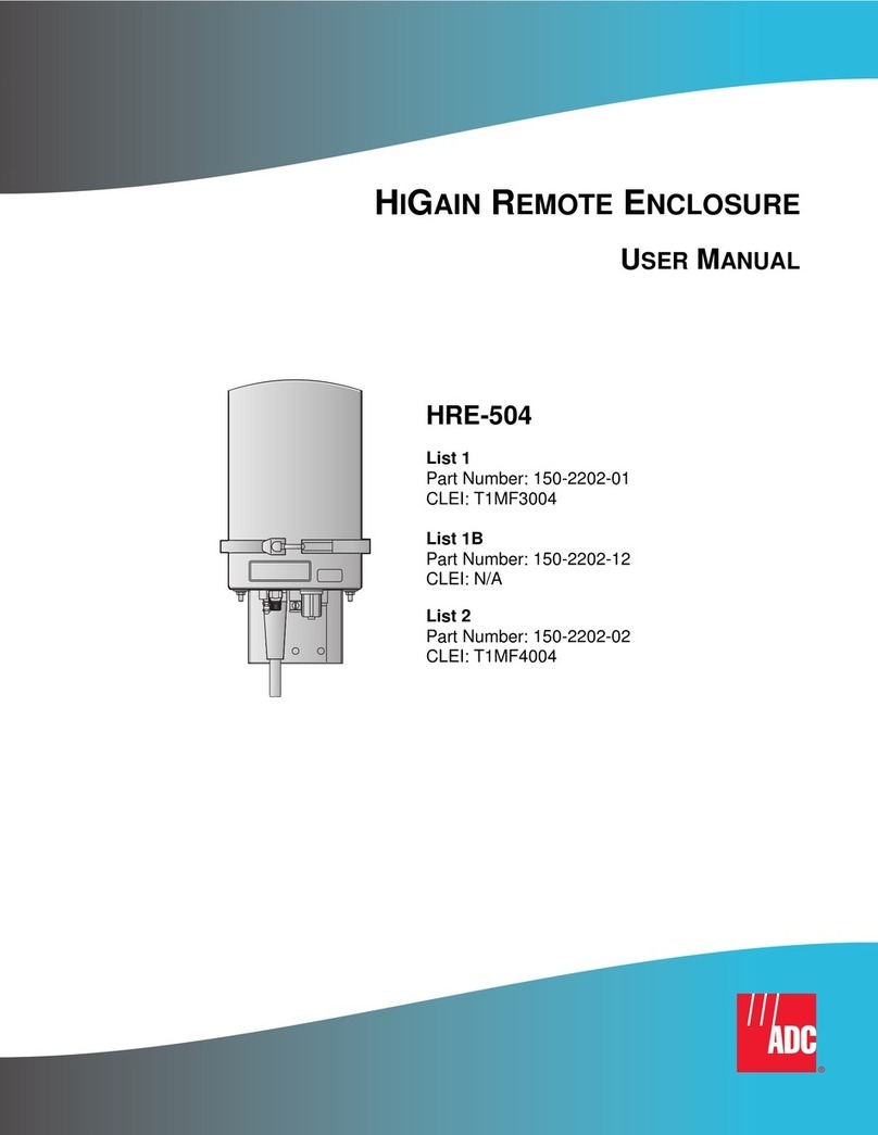
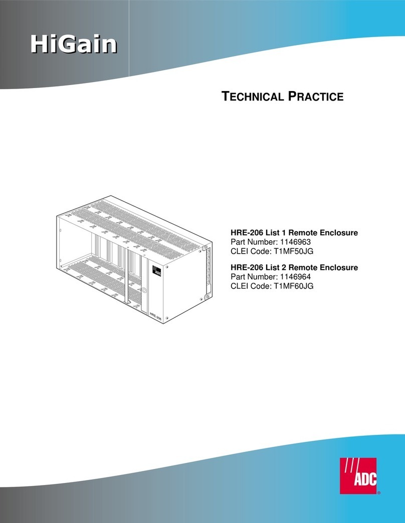
ADC HiGain HRE-500 List 1 User manual

USER MANUAL
HRE-500 List 1
HiGain Remote Enclosure
Product Catalog: HRE-500-L1
CLEI: T1R4EGDC

150-500-100-05
ii July 25, 2002 HRE-500 List 1
Revision History
Copyright
July 25, 2002
© 2002 ADC DSL Systems, Inc. All rights reserved.
Trademark Information
ADC is a registered trademark of ADC Telecommunications, Inc. HiGain is a
registered trademark of ADC DSL Systems, Inc. No right, license, or interest to such
trademarks is granted hereunder, and you agree that no such right, license, or interest
shall be asserted by you with respect to such trademark. Other product names
mentioned in this practice are used for identification purposes only and may be
trademarks or registered trademarks of their respective companies.
Disclaimer of Liability
Information contained in this document is company private to ADC DSL Systems, Inc.,
and shall not be modified, used, copied, reproduced or disclosed in whole or in part
without the written consent of ADC.
Contents herein are current as of the date of publication. ADC reserves the right to
change the contents without prior notice. In no event shall ADC be liable for any
damages resulting from loss of data, loss of use, or loss of profits, and ADC further
disclaims any and all liability for indirect, incidental, special, consequential or other
similar damages. This disclaimer of liability applies to all products, publications and
services during and after the warranty period.
Revision Release Date Revisions Made
01 March 27, 1998 Initial release of document
02 June 16, 1998 •Changed stub description
•Added internal HRE-500 description
•Added grounding information
•Changed illustrations 1, 2, 3, 4, 6
03 April 15, 1999 Changed from 6-pair to 4-pair stub
04 September 24, 1999 Enhanced standards compliances
05 July 25, 2002 Rebranding-no technical changes
150-500-100-05 Using This Manual
HRE-500 List 1 July 25, 2002 iii
USING THIS MANUAL
Two types of messages, identified by icons, appear in the text.
UNPACK AND INSPECT YOUR SHIPMENT
Upon receipt of the equipment:
•Unpack each container and inspect the contents for signs of damage. If
the equipment has been damaged in transit, immediately report the extent
of damage to the transportation company and to ADC DSL Systems, Inc.
Order replacement equipment, if necessary.
•Check the packing list to ensure complete and accurate shipment of each
listed item. If the shipment is short or irregular, contact ADC DSL
Systems, Inc. as described in “Appendix C - Glossary” on page 18. If you
must store the equipment for a prolonged period, store the equipment in
its original container.
Notes contain information about special circumstances.
Cautions indicate the possibility of equipment damage or the
possibility of personal injury.

Table of Contents 150-500-100-05
iv July 25, 2002 HRE-500 List 1
TABLE OF CONTENTS
Overview________________________________________________1
Features ....................................................................................1
Applications..............................................................................2
Product Description_______________________________________3
External Mechanics ..................................................................4
Status LED .................................................................4
HRE-500 Stub............................................................5
Ground Wire ..............................................................6
End Cap......................................................................6
Internal Mechanics ...................................................................7
Card-edge Connector .................................................8
Gas-tube Protectors....................................................8
Thermal Deployment Limits......................................8
Bar Code and Configuration Number Information ..................9
Installation _____________________________________________10
Installation Kit........................................................................10
Tools.......................................................................................10
Installing Doublers .................................................................11
Mounting the Enclosure .........................................................13
Grounding...............................................................................14
Appendix A - Specifications _______________________________15
Appendix B - Product Support_____________________________16
Appendix C - Glossary ___________________________________18
Certification and Warranty _______________________________19

150-500-100-05 Overview
HRE-500 List 1 July 25, 2002 1
OVERVIEW
The ADC®HiGain®Remote Enclosure Model HRE-500 List 1 is a
weatherproof, outdoor, single-slot enclosure that houses one of the following
units:
•HiGain Mini Doublers
–HDU-217
–HDU-219
–HDU-437
–HDU-439
•HiGain Micro Doublers
–HDU-409
–HDU-407
•239 T1 Repeater
•ETSI Mini Doublers
–EDU-840
–EDU-841
FEATURES
•compact dimensions
•eliminates need for expensive controlled environmental vaults
•unaffected by dust, wind, rain, sleet, ice, and snow
•easily mounted with two screws on a wall or pole
•weather-sealing cable fittings that protect connections and provide strain
relief
•easy-open bottom cap, secured by one retaining screw and five
compression bolts
•compatible with above and below ground installations
•replaceable gas tube surge voltage protection on all four ports

Overview 150-500-100-05
2 July 25, 2002 HRE-500 List 1
APPLICATIONS
The HRE-500 List 1 houses doublers and allows quick and easy deployment
of an ADC single or multi-doubler circuit, as shown in Figure 1.
Figure 1. HRE-500 List 1 Applications
Doubler
2
HRE-500
Loop 1
Loop 2
Span 2
Loop 1
Loop 2
Span 1
Doubler
N
HRE-500
Loop 1
Loop 2
Span 3
Remote
Unit
Loop 1
Loop 2
Span N+1
Doubler
1
HRE-500
Line
Unit
(b)
Remote
Unit
Loop 1
Loop 2
Span 2
Loop 1
Loop 2
Span 1
Doubler
HRE-500
Line
Unit
(a)
(a) Single doubler system
(b) N doubler system (N 4). In applications where N≤≥3, all doublers must be
HDU-409s, EDU-409s or HDU-407s.

150-500-100-05 Product Description
HRE-500 List 1 July 25, 2002 3
PRODUCT DESCRIPTION
The HRE-500 List 1 includes:
•External mechanics featuring:
–Status LED viewing hole
–20-foot gel-filled stub
–Ground wire
–End cap
•Internal mechanics featuring:
–Card-edge connector
–Gas-tube protectors

Product Description 150-500-100-05
4 July 25, 2002 HRE-500 List 1
EXTERNAL MECHANICS
Figure 2 shows the external mechanics of the HRE-500 List 1 including the
status LED viewing lens, cable stub wiring assignments and enclosure
dimensions.
Figure 2. HRE-500 List 1 External Mechanics
Status LED
The doubler single state LED can be viewed through the housing shown in
Figure 2. Consult the appropriate doubler practice for information regarding
the status LED.

150-500-100-05 Product Description
HRE-500 List 1 July 25, 2002 5
HRE-500 Stub
The HRE has a 14 AWG, stranded ground wire and a four-pair, 20-foot
gel-filled stub for access to the doubler’s four ports. This 24 AWG stub has
foam skin insulation and a filled jacket. Each conductor has a dual insulation
consisting of an inner coating of natural, insulating-grade, high-density
cellular polyethylene covered by an outer skin of color-coded, high-density
solid polyethylene. Standard color codes allow for pair identification with
color compounds chosen for electrical balance and permanency. The
assembly is flooded with an Electro Thermo Plastic Rubber (ETPR)
compound, filling the air space between conductors.
A non-hygroscopic core wrap protects the core and provides improved
mechanical and electrical characteristics. The inner surface of the core wrap
is coated with the ETPR filling compound. The outer surface is coated with
an amorphous polypropylene compound. The cable core shield is a
corrugated copolymer-coated 8 mil aluminum tape. The outer jacket consists
of a black, low-density polyethylene material providing a flexible protective
covering that withstands exposure to sunlight, atmospheric temperatures,
ground chemicals and stresses expected in standard installations. The cable
complies with the requirements of ANSI/ICEA S-84-608-1994 and has an
outside diameter of 0.38 inches (10 mm).
The stub’s four pairs terminate on an internal assembly that contains the
card-edge connector and gas tube protector board. The stub pairs are routed
through a ferrite coil, which prevents EMI energy from exiting the stub pairs.
Figure 3 shows the identity of the four ports for each cable stub to provide
access. The CO ports connect to the upstream cable pair connections of either
another doubler or the line unit. The field ports connect to the downstream
cable pair connections of either another doubler or remote unit.
Figure 3. HRE-500 Wiring Diagram

Product Description 150-500-100-05
6 July 25, 2002 HRE-500 List 1
Ground Wire
The ground wire is required for both EMI and voltage surge protection for the
installed doubler.
End Cap
There are five compression bolts on the end cap which work to create a
waterproof barrier. When properly torqued, these bolts compress the
neoprene washer (shown in Figure 4) that sits between the enclosure’s two
end plates. The washer expands against the sides of the enclosure to form a
waterproof barrier. This allows the enclosure to be installed anywhere in the
network, including underground locations where it may be submerged in
water.

Product Description 150-500-100-05
8 July 25, 2002 HRE-500 List 1
Card-edge Connector
See Figure 3 on page 5 for the wiring diagram specifications.
Gas-tube Protectors
The four replaceable gas-tube protectors are equivalent to a TII 47BT and
have a breakdown voltage ranging from 300 V to 500 V. The breakdown
voltage is a function of voltage rise-time. The tubes can withstand at least
400, 10/1000, 500 Amp discharges.
Thermal Deployment Limits
HRE-500 and its doubler can be deployed in an ambient temperature up to
135 °F (57 °C) with full solar load and 145 °F (63 °C) without solar load.
A replacement kit containing 20, TII 47BT, gas-tube
protectors is available from ADC (part #132-1028-01). See
“Appendix B - Product Support” on page 16 for ordering
information.

150-500-100-05 Product Description
HRE-500 List 1 July 25, 2002 9
BAR CODE AND CONFIGURATION NUMBER
INFORMATION
Figure 5 shows the locations of the bar code and configuration number labels.
Table 1 gives a brief description of what the label represents.
Figure 5. Bar Code and Configuration Number Locations
Table 1. Bar Code and Configuration Number Label Descriptions
Number Components
CLEI/ECI Bar Code Label Contains human-readable Common Language Equipment
Identifier (CLEI) number and Equipment Catalog Item (ECI)
bar code number.
Configuration Number This label contains the configuration or revision number,
the part number, the Julian date, and a barcoded serial
number.
CLEI/ECI
bar code
Configuration number
(on back plate)

Installation 150-500-100-05
10 July 25, 2002 HRE-500 List 1
INSTALLATION
This section provides information on installing a doubler or repeater in the
HRE-500 List 1 and on mounting the enclosure. Part number and wiring
information are also included.
INSTALLATION KIT
The HRE-500 installation kit components are listed in Table 2. If any items
are missing, or if the shipment is damaged, please contact your ADC sales
representative.
TOOLS
To install the HRE-500, you need the following tools:
•flathead screwdriver
•drill
•wood, metal or concrete drill bit, depending on the installation surface
•torque wrench
Table 2. Installation Kit
Part Number Quantity Description
150-500-100 1HiGain Remote Enclosure (HRE) 500 Technical Practice
670-1018-24 2Screws, 12 x 1 in.
673-1095-01 13/16 in. Hex (Allen) Wrench
672-1001-04 2Flat Washers 1/4 in. inside diameter (ID) 1/2 in. outside
diameter (OD)
671-1002-04 2Anchor nuts

150-500-100-05 Installation
HRE-500 List 1 July 25, 2002 11
INSTALLING DOUBLERS
To install a doubler in the HRE-500:
1Remove the small retaining screw from the lower front side of the case
(see Figure 2 on page 4).
2Loosen, but do not remove, the five compression bolts from the end cap
(see Figure 2), then remove the end cap.
3Insert the doubler or repeater into the end cap’s connector.
4Replace the case, then insert the retaining screw.
5Torque the five compression bolts in the proper sequence shown in
Figure 6 and Table 3 on page 12).
Figure 6. End Cap Compression Bolts
The five compression bolts must be torqued according to their
specified torque levels and in the numerical sequence shown in
Table 3 on page 12.

Installation 150-500-100-05
12 July 25, 2002 HRE-500 List 1
Always follow the torquing sequence in Table 3. Exact
torquing pressure is only required for installation in which the
HRE-500 may be submerged in water. Approximate torquing
is sufficient in all other installations.
Table 3. Torque Sequence Chart
Number
Sequence Torque
160 inch/pounds
265 inch/pounds
365 inch/pounds
465 inch/pounds
565 inch/pounds
185 inch/pounds
285 inch/pounds
385 inch/pounds
485 inch/pounds
585 inch/pounds
190 inch/pounds

150-500-100-05 Installation
HRE-500 List 1 July 25, 2002 13
MOUNTING THE ENCLOSURE
To mount the enclosure:
1Select a location for mounting the HRE-500 that allows access to wiring
and grounding connections through the cable fittings on the bottom of the
HRE-500.
2Place the HRE-500 in the chosen mounting location, then mark the
mounting hole locations. Figure 7 shows the mounting hole locations on
the enclosure.
Figure 7. Mounting Hole Locations (Front View)

Installation 150-500-100-05
14 July 25, 2002 HRE-500 List 1
3Do one of the following:
•If the installation location is wood, use a drill with a wood or metal
drill bit to drill mounting screw holes into the surface.
•If the installation location is concrete, use a drill with a concrete drill
bit that is slightly smaller than the diameter of the anchor nuts to drill
the mounting screw holes into the concrete surface.
4Insert the anchor nuts into the pilot holes and tap the anchor nuts into
place with a hammer.
5Use a 1/4inch slotted screwdriver to fasten the enclosure onto the
mounting location using the two screws and two washers provided in the
installation kit.
GROUNDING
The stub shield is not connected to the enclosure ground. When the stub is
spliced with the main cable the stub shield should be connected to the field
cable shield. Failure to do so will expose the signal pairs to stray EMI which
could introduce service affecting noise into the information payload. The
green ground wire must also be properly grounded to provide both EMI and
voltage surge protection to the doubler.

150-500-100-05 Appendix A - Specifications
HRE-500 List 1 July 25, 2002 15
APPENDIX A - SPECIFICATIONS
The HRE-500 List 1 outer enclosure has the following specifications:
Length 12 in. (30.7 cm.)
Width 3 in. (7.7 cm.)
Depth 2in.(5.12cm.)
Weight 2.5 lbs. (1.13 kg.)

Appendix B - Product Support 150-500-100-05
16 July 25, 2002 HRE-500 List 1
APPENDIX B - PRODUCT SUPPORT
ADC Customer Service Group provides expert pre-sales and post-sales
support and training for all its products.
Technical support is available 24 hours a day, 7 days a week by contacting
the ADC Technical Assistance Center (TAC).
Sales Assistance
800.366.3891 extension 73000
(USA and Canada)
952.917.3000
Fax: 952.917.3237
•Quotation Proposals
•Ordering and Delivery
•General Product Information
Systems Integration
800.366.3891, extension 73000
(USA and Canada)
952.917.3000
•Complete Solutions (from concept to
installation)
•Network Design and Integration Testing
•System Turn-Up and Testing
•Network Monitoring (upstream or downstream)
•Power Monitoring and Remote Surveillance
•Service/Maintenance Agreements
•Systems Operation
ADC Technical Assistance
Center
800.638.0031
714.730.3222
Fax: 714.730.2400
Email: wsd_support@adc.com
•Technical Information
•System/Network Configuration
•Product Specification and Application
•Training (product-specific)
•Installation and Operation Assistance
•Troubleshooting and Repair/Field Assistance
Online Technical Support •www.adc.com/Knowledge_Base/index.jsp
Online Technical Publications •www.adc.com/library1/
This manual suits for next models
1
Table of contents
Other ADC Enclosure manuals

ADC
ADC Fiber Optic Wall Box FL1000 Series Operating and safety instructions

ADC
ADC WorldDSL EMS-830T User manual

ADC
ADC HRE-506 User manual

ADC
ADC HiGain HRE-450 List 4A User manual

ADC
ADC FRE-765 User manual

ADC
ADC HiGain HRE-427 User manual

ADC
ADC HRE-454 User manual

ADC
ADC HiGain HRE-450 List 4A User manual

ADC
ADC TrueNet Rack Mount Fiber Enclosures RMG... User manual

ADC
ADC OmniReach FDH 3000 User manual