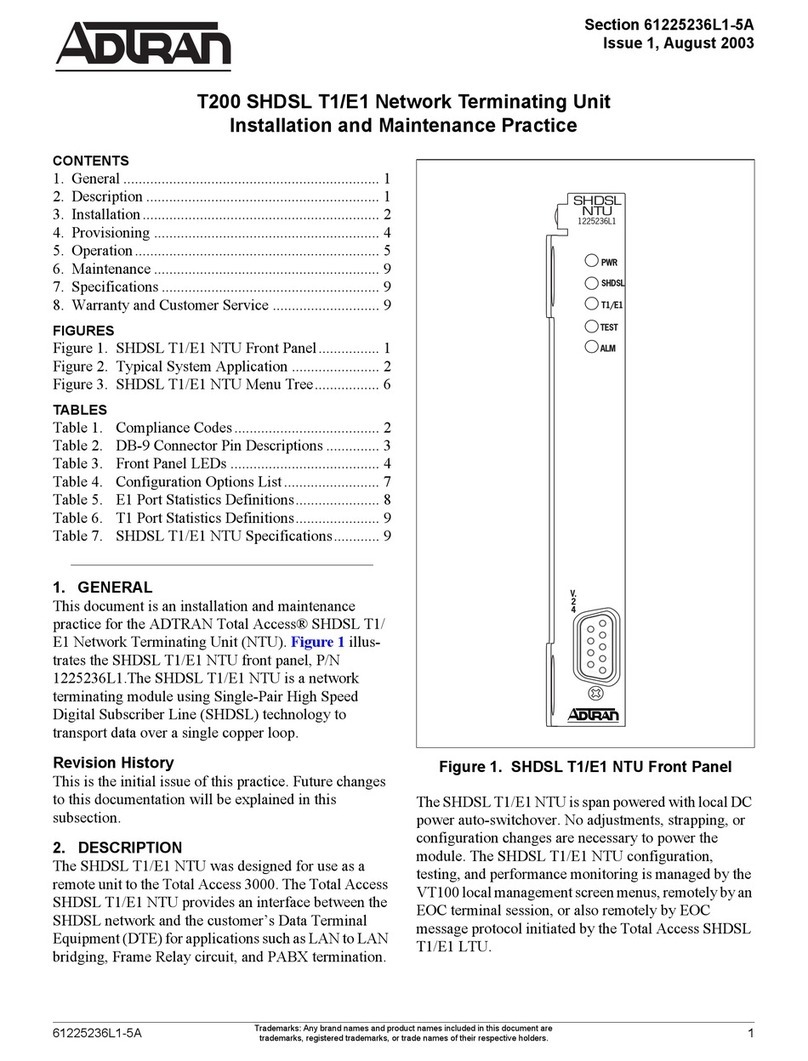
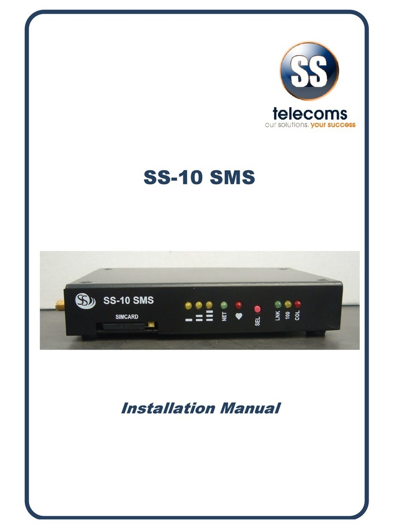
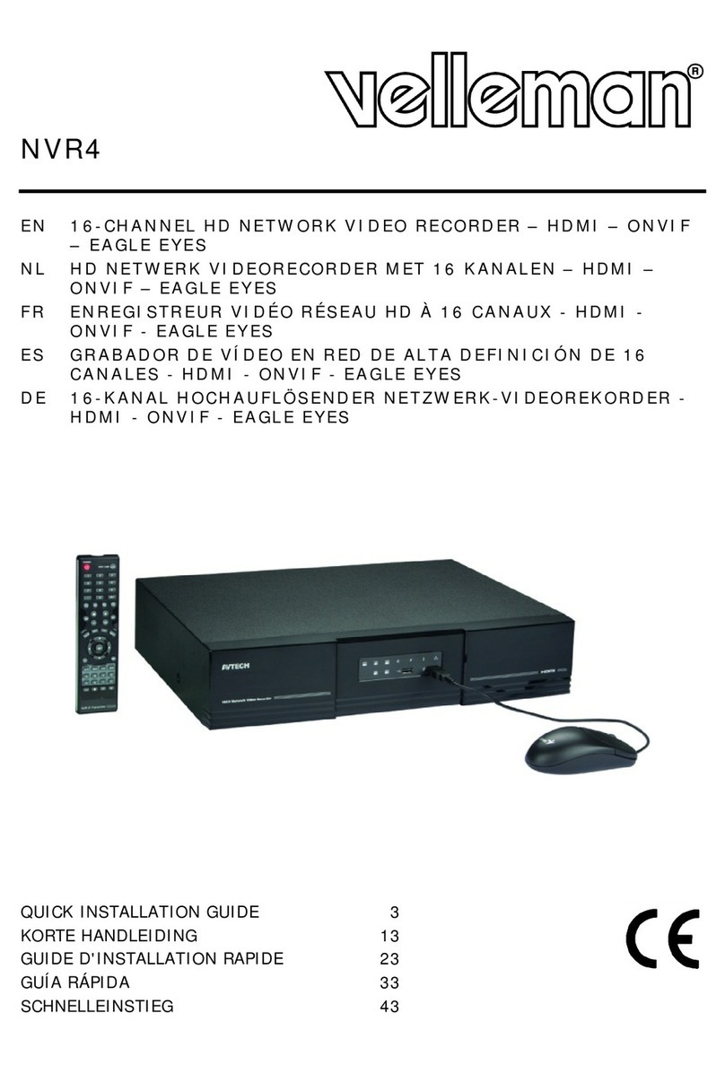
Proscend 708E Series User manual

708E Series
8 Port PoE Long Reach
Switch / Extender
User Manual
Version 1.00

708E Series User Manual
1
Table of Contents
Introduction.......................................................................................................................1
1.1 Features .....................................................................................................................1
1.2 Specifications..............................................................................................................2
Hardware Description .......................................................................................................5
2.1 Line Port Pin Assignment............................................................................................5
2.2 DIN-rail Mounting........................................................................................................6
2.3 Wall Mounting.............................................................................................................6
2.4 Rack Mounting............................................................................................................7
LED Definition ...................................................................................................................8
3.1 LED Indicators ............................................................................................................8
Power Connection.............................................................................................................9
Ground Connecting...........................................................................................................9
Web Management............................................................................................................10
6.1 Access the Web Configurator....................................................................................10
6.2 Web Interface ...........................................................................................................11
6.2.1 Information............................................................................................................11
6.2.2 Status of Interface Status......................................................................................12
6.2.3 Config / Interface of Device Setting.......................................................................14
6.2.4 Config/Port............................................................................................................15
6.2.5 User......................................................................................................................18
6.2.6 Ping.......................................................................................................................18
6.2.7 Load Default..........................................................................................................19
6.2.8 Upgrade................................................................................................................19
6.2.9 Reboot..................................................................................................................21
6.2.10 Logout...............................................................................................................21
Precautions and Safety Warnings..................................................................................22

708E Series User Manual 1
Introduction
The 708EPI-DC and 708EP-AC Long Reach Switches / Extenders feature 8 pairs of Long Reach
Ethernet solutions with the companion the Ethernet Extender 101EPI remote devices connecting
to each port of the 708E Series. Each solution pair carries Ethernet traffic and power over Ethernet
cable up to 800 meters.
The 708EPI-DC is designed as an industrialgrade, compact device working in harsh environments,
while the 708EP-AC is 19” rack mounted with built-in power supply. Without the needs of redundant
long-distance power cabling, each 101EPI receives power from any port of the 708E Series and
offers 802.3at Power-over-Ethernet for the remote devices such as IP cameras.
With the intelligence of built-in LFPT (Link Fault Pass Through) function in the 708EPI-DC and the
708EP-AC, the network administrator is enabled to monitor the link status easily, or turn on and off
an IP camera remotely from the control center for eliminating the maintenance time and cost.
1.1 Features
Ethernet over UTP cable up to 800 meters.
Eliminate long distance power cabling.
6KV surge protection.
Web management.
LFPT (Link Fault Pass Through) per each port.
Industrial design for operation in harsh environments (708EPI-DC).
Built-in power supply (708EP-AC).

708E Series User Manual 2
1.2 Specifications
Hardware Interfaces
RJ45 Uplink port
LINE port x 8 : Passive PoE PSE
Power Input:
2-pin Terminal Block (708EPI-DC)
AC Power Socket (708EP-AC)
Standard Compliances
IEEE 802.3af/IEEE 802.3at
IEEE 802.3/802.3u/802.3x/802.3ab compliant
Management
Web-based Management
TFTP firmware upgrade
PoE Status Monitoring
Support Link Fault Pass Through (LFPT)
Mechanical
708EPI-DC
Dimensions (W x H x D): 40 x 155 x 105 mm
Weight: 0.53 kg
DIN-rail and Wall Mounting
IP40
708EP-AC
Dimensions (W x H x D): 404 x 44.5 x 177 mm
Weight: 2.34 kg
Rack Mounting
Power
708EPI-DC
Power Input: 55~57VDC
System power consumption 10W
PoE power budget:200W
708EP-AC
Power Input: 100~240VAC 60/50Hz
System power consumption 10W
PoE power budget:188W
LED Indicators
Power, System, Port Status, PoE
Environment & Regulatory Compliance
708EPI-DC Operating Temperature: -40 to +75°C
708EP-AC Operating Temperature: 0 to +45°C
Storage Temperature: -40 to +85°C
Humidity: 5 to 95% RH (non-condensing)
EMC: FCC Part 15 subpart B, EN55032 Class A ,
CISPR 32, UKCA, EN300386, EN55035, CISPR35
Electrical Safety: EN 62368-1
EN50121-4 Compliant (708EPI-DC)
RoHS (Pb fee) and REACH compliant
MTBF: > 25 years (708EPI-DC)
>22 years (708EP-AC)

708E Series User Manual 3
Data and Power Range
Cat 6 UTP 4 Pairs, 708EPI-DC @75°C
PoE Power Budget 200W
Cat 6 UTP 2 Pairs, 708EPI-DC @75°C
PoE Power Budget 200W
Distance
Link Speed
101EPI PoE
output (watt)
Distance
Link Speed
101EPI PoE
output (watt)
100 meters
100Mbps
30.0
100 meters
100Mbps
28.0
200 meters
100Mbps
28.0
200 meters
100Mbps
25.0
300 meters
100Mbps
26.5
300 meters
100Mbps
21.5
400 meters
100Mbps
25.0
400 meters
100Mbps
15.5
500 meters
100Mbps
23.5
500 meters
100Mbps
12.0
600 meters
10Mbps
21.5
600 meters
10Mbps
10.0
700 meters
10Mbps
18.0
700 meters
10Mbps
8.0
800 meters
10Mbps
15.5
800 meters
10Mbps
6.5
900 meters
N/A
N/A
900 meters
N/A
N/A
Cat 6 UTP 4 Pairs, 708EP-AC @25°C
PoE Power Budget 188W
Cat 6 UTP 2 Pairs, 708EP-AC @25°C
PoE Power Budget 188W
Distance
Link Speed
101EPI PoE
output (watt)
Distance
Link Speed
101EPI PoE
output (watt)
100 meters
100Mbps
29.0
100 meters
100Mbps
27.5
200 meters
100Mbps
27.5
200 meters
100Mbps
24.0
300 meters
100Mbps
25.5
300 meters
100Mbps
19.5
400 meters
100Mbps
24.0
400 meters
100Mbps
14.0
500 meters
100Mbps
22.0
500 meters
100Mbps
11.0
600 meters
10Mbps
19.5
600 meters
10Mbps
8.5
700 meters
10Mbps
16.5
700 meters
10Mbps
7.0
800 meters
10Mbps
14.0
800 meters
10Mbps
6.0
900 meters
N/A
N/A
900 meters
N/A
N/A

708E Series User Manual 4
Dimensions
Ordering Information
Model Name
Description
708EPI-DC
8-Port PoE Long Reach Switch/Extender, DC power input
708EP-AC
8 Port PoE Long Reach Switch/Extender, AC power input
NOTE: Features and specifications are subject to change without prior notice.

708E Series User Manual 5
Hardware Description
2.1 Line Port Pin Assignment
The LINE interfaces of the 708E Series are standard 8-pin RJ45 connectors. The following tables
display the pinouts.
MDI Port Pinouts
MDI-X Port Pinouts
Pin
Desc
r
i
p
t
io
n
Pin
Desc
r
i
p
t
io
n
1
TX+
1
RX+
2
TX-
2
RX-
3
RX+
3
TX+
4
Not used
4
Not used
5
Not used
5
Not used
6
RX-
6
TX-
7
Not used
7
Not used
8
Not used
8
Not used
The PoE pinouts of the LINE interfaces are as below when 8 wires are connected.
PoE Pinouts
Pin
Desc
r
i
p
t
io
n
Pin
Desc
r
i
p
t
io
n
1
V+
5
V+
2
V+
6
V-
3
V-
7
V-
4
V+
8
V-
The PoE pinouts of the LINE interfaces are as below when 4 wires are connected.
PoE Pinouts
Pin
Desc
r
i
p
t
io
n
Pin
Desc
r
i
p
t
io
n
1
V+
5
Not used
2
V+
6
V-
3
V-
7
Not used
4
Not used
8
Not used

708E Series User Manual 6
2.2 DIN-rail Mounting
The DIN-rail mounting is only for the 708EPI-DC.
Mounting Step
STEP 1: Hook the unit over the DIN-rail.
STEP 2: Push the bottom of the unit towards the DIN-rail until it snaps into place.
Removal Step
STEP 1: Push the unit down to free the bottom of the DIN-rail.
STEP 2: Rotate the bottom of the unit away from the DIN-rail.
STEP 3: Unhook top of unit from DIN-rail.
2.3 Wall Mounting
The wall mounting is only for the 708EPI-DC.
STEP 1:At the bottom side of the device, use two screws to install each bracket.
NOTE: Each screw type is flat head M3 x 4 mm.
STEP 2: Use the screws to attach the bracket of the device for wall mounting.
NOTE: These screws are not included in the package. The head of each screw is less than 7 mm in
diameter, the shaft is less than 3 mm in diameter, and the length is less than 10 mm in diameter.

708E Series User Manual 7
2.4 Rack Mounting
The rack mounting is only for the 708EP-AC.
STEP 1: Align two brackets with the holes on the sides of the Switch and fasten the mounting kits
by using screws.
NOTE: The type of screw is flat head M3 x 5mm.
STEP 2:After attaching two brackets, line up the rack-mounting positions of the holes in the
brackets with the appropriate holes on the rack and then fasten the Switch on the rack by
using screws
NOTE: The rack mounting screws are not inclouded in the package.

708E Series User Manual 8
LED Definition
3.1 LED Indicators
The function of each LED indicator on the front panel is described in the following table.
LED
Color
State
Description
PWR
Green
On
Device Power On.
Off
Device Power Off.
SYS
Green
On
System is working.
Off
System is off.
Blinking
Device Error.
PoE1~8
Green
On
Powered Device Connected.
Off
Powered Device Disconnected.
UPLINK
Green
On
1000Mbps UPLINK LINK UP.
Off
1000Mbps UPLINK LINK DOWN.
Blinking
1000Mbps Data Transmitting.
Yellow
On
100/10Mbps UPLINK LINK UP.
Off
100/10Mbps UPLINK LINK DOWN.
Blinking
100/10Mbps Data Transmitting.
LINE 1~8
Green
On
100Mbps LINE LINK UP.
Off
LINE LINK DOWN.
Blinking
100Mbps Data Transmitting.
Yellow
On
10Mbps LINE LINK UP.
Off
LINE LINK DOWN.
Blinking
10Mbps Data Transmitting.

708E Series User Manual 9
Power Connection
For 708EPI-DC
The power input interface is the 2-pin terminal block (+, -) on the front panel and is provided
the power input voltage 55 ~ 57 VDC/5Afrom the power supply.
Insert the positive and negative wires into V+ and V- contact on the terminal block and tighten
the wire-clamp screws to prevent the wires from being loosened.
For 708EP-AC
Use the included power cord to connect the power socket on the front panel to a power outlet.
Ground Connecting
To prevent the effects of noise from electromagnetic interference (EMI), run the ground connection
from the ground screw to the grounding surface before connecting the devices.

708E Series User Manual 10
Web Management
The web configuration is a HTML-based management interface for quick and easy to set up.
6.1 Access the Web Configurator
After properly connecting the hardware as previously explained. Launch your web browser and
enter http://192.168.1.1 as URL. The default IP address, username, and password are as follows.
Default IP Address: 192.168.1.1
Default Username: root
Default Password: 2wsx#EDC
Please fill in the default username root and the default password 2wsx#EDC, and then click Login.
For the system security, changing the default password is strongly suggested after configuration.
You can go to the User setting to reset.
NOTE:
•The device only supports one web session.
•The timeout of web session is 15 minutes.

708E Series User Manual 11
6.2 Web Interface
6.2.1 Information
The system information is shown as below.
(1) System shows Model Name, Hardware MCSV, Software MCSV, Software Version, PSE
Software Version, MAC Address, Serial Number and System Up Time.

708E Series User Manual 12
6.2.2 Status of Interface Status
This section includes Interface Status Switch, Port Status and PSE Port Status.
(1) The setting of Refresh Interval allows you to set up how long the information status is updated.
(2) The Switch Port Status includes Broadcast/ Multicast / Unicast status and Link Status
information by each port. Users can view the statistics of the port Receive packets and
Transmit Packets through this page.

708E Series User Manual 13
(3) The PSE Port Status includes Detect / Voltage / Current /Power information by each port and
Temperature of PSE chipset.
According to IEEE 802.3af-2003 standard, a PSE may optionally classify a PD for power
management purposes, prior to applying full operating power. The following table lists the
different classes according to power at PSE output and PD input.
Class
Usage
Classification
current (mA)
Power range
at PD (W)
Max power
from PSE (W)
Class
description
0
Default
0–5
0.44–12.94
15.4
Classification
unimplemented
1
Optional
8–13
0.44–3.84
4
Very Low
power
2
Optional
16–21
3.84–6.49
7
Low power
3
Optional
25–31
6.49–12.95
15.4
Mid power
4
Valid for Type 2
(802.3at) devices, not
allowed for 802.3af
devices
35–45
12.95–25.50
30
High power

708E Series User Manual 14
6.2.3 Config / Interface of Device Setting
This section includes LAN and SNMP Setting of Device.
(1) LAN Setting can set up DHCP Client Mode, IPAddress, IP Netmask, Gateway Address, DNS
Primary, and DNS Secondary.
Device can obtain IP/ Netmask / Gateway/ DNS from DHCP server if you are enabled “DHCP
Client Mode”.
The related information will show on ‘Status’ page as follows.

708E Series User Manual 15
(2) The SNMP Trap Setting for TRAP target configure which allows the user to configure. If you
configure the Trap Mode is enabled and the setting is successful, the SNMP TRAP function
will take effect. In the event of link up or link down, the switch will automatically send the TRAP
packet to destination address.
NOTE: The SNMP Trap is supported SNMP-V1 only.
NOTE: The SNMP Trap supports.
6.2.4 Config/Port
This section includes Line / LFPT and LAN Speed Setting.
(1) Line Port: It allows you to select Line port Enable or Disable by each port.
If you are disabled the Line port it unable to provide power to PD and establish
connectivity.

708E Series User Manual 16
The total maximum power budget depends on the device you use.
708EPI-DC: PoE power budget is 200W.
708EP-AC: PoE power budget is 188W.
The detailed power available budget is shown as the following table.
Cat 6 UTP 4 Pairs, 708EPI-DC @75°C
PoE Power Budget 200W
Cat 6 UTP 2 Pairs, 708EPI-DC @75°C
PoE Power Budget 200W
Distance
Link Speed
101EPI PoE
output (watt)
Distance
Link Speed
101EPI PoE
output (watt)
100 meters
100Mbps
30.0
100 meters
100Mbps
28.0
200 meters
100Mbps
28.0
200 meters
100Mbps
25.0
300 meters
100Mbps
26.5
300 meters
100Mbps
21.5
400 meters
100Mbps
25.0
400 meters
100Mbps
15.5
500 meters
100Mbps
23.5
500 meters
100Mbps
12.0
600 meters
10Mbps
21.5
600 meters
10Mbps
10.0
700 meters
10Mbps
18.0
700 meters
10Mbps
8.0
800 meters
10Mbps
15.5
800 meters
10Mbps
6.5
900 meters
N/A
N/A
900 meters
N/A
N/A
Cat 6 UTP 4 Pairs, 708EP-AC @25°C
PoE Power Budget 188W
Cat 6 UTP 2 Pairs, 708EP-AC @25°C
PoE Power Budget 188W
Distance
Link Speed
101EPI PoE
output (watt)
Distance
Link Speed
101EPI PoE
output (watt)
100 meters
100Mbps
29.0
100 meters
100Mbps
27.5
200 meters
100Mbps
27.5
200 meters
100Mbps
24.0
300 meters
100Mbps
25.5
300 meters
100Mbps
19.5
400 meters
100Mbps
24.0
400 meters
100Mbps
14.0
500 meters
100Mbps
22.0
500 meters
100Mbps
11.0
600 meters
10Mbps
19.5
600 meters
10Mbps
8.5
700 meters
10Mbps
16.5
700 meters
10Mbps
7.0
800 meters
10Mbps
14.0
800 meters
10Mbps
6.0
900 meters
N/A
N/A
900 meters
N/A
N/A

708E Series User Manual 17
(2) Link Fault Pass Through (LFPT)
LFTP must be used with Long Reach Switch / Extenders arranged in pairs, and both devices
must support LFPT. If only one device is used, the LFPT function will not work properly
It allows you to select LFPT Enable or Disable and has been further enhanced for monitoring
and maintenance purposes.
Link Fault Pass Through on the 708E Series can be enabled/disabled via WEB configuration
and the 101EPI can be enabled/disabled via DIP switch on the device individually, and has
been further enhanced for monitoring and maintenance purposes.
Example-1:
In case of cable breaks between 708EPx and 101EPI ,the 708EPx detects cable break at P2
then trigger LINK DOWN at P0(uplink port) and it will send a trap alert to the network
administrator and 101EP turn off the PoE out.
Example-2:
In case of cable breaks ,the 708EPx detects cable break at P0 (uplink) then trigger LINK
DOWN and turn off power out at P2 (Line) and it will sends a trap alert to the network
administrator and the 101EP can’t offer Power out to PD (Powered Device).

708E Series User Manual 18
(3) Auto/10M: It allows you to select LAN Speed 100Mbps or 10Mbps.
6.2.5 User
This section allows you to set up and change your username and password for different level users.
The users setting is shown in the interface as below.
Item
Description
User name
Enter user name
Password
Enter Password
Level
Administrator: user can setup and read anything
Normal: user can setup and read anything, but Admin session
Guest: user only can read status
NOTE: Username and password can accept a maximum length of 31 characters.
6.2.6 Ping
The Ping Setting is shown in the interface as below.
This manual suits for next models
2
Table of contents
Other Proscend Network Hardware manuals
