LOOPBACK TESTING
Initiate loopback testing from the maintenance menus. The inband codes shown below can
be sent by a test set.
Table 1. GNLB Loopback Commands
Loopback Inband Code Description
NLOC 1111000 DSX-1 signal is looped back to the network at the H2TU-C.
NREM 1110000 DSX-1 signal is looped back to the network at the H2TU-R.
CREM 1111110 DS1 signal from customer is looped back to the customer at the H2TU-C.
CLOC 1111100 DS1 signal from customer is looped back to the customer at the H2TU-R.
SMJK 11000 DSX-1 signal is looped back to the network at the H2TU-R SmartJack module.
Loopdown 11100 Deactivates any of the above loopbacks.
Table 2. LED Status and Functions
LED and Status Function
DSL
OFF No power is applied to the H2TU-C.
Solid green Normal operation: HDSL2 span is synchronized without error.
Solid red HBER, MARG, or PWRF alarm is present at the H2TU-C.
Flashing red once every second HDSL2 loop is attempting synchronization.
ALM
OFF Normal operation: the DSX-1 signal is present at both the H2TU-R and
H2TU-C.
Solid yellow RLOS is present at the H2TU-R.
Solid red LLOS is present at the H2TU-C.
DSX/DS1
Solid green Normal operation: the DSX-1 signal is error free.
Solid red LLOS, BPV, frame error, or CRC is present at the H2TU-C.
ESF/SF
OFF Unframed DSX-1 is present at the H2TU-C, unit set as unframed, or no
DSX-1 is detected at the H2TU-C.
Solid yellow ESF frame formatting is present at the H2TU-C.
Flashing yellow once every second ESF frame formatting and frame error/CRC are present at the H2TU-C.
Solid green SF frame formatting is present at the H2TU-C.
Flashing green once every second SF frame formatting and frame error are present at the H2TU-C.
B8ZS/AMI
OFF No DSX-1 signal is present at the H2TU-C.
Solid yellow B8ZS is present at the H2TU-C.
Flashing yellow once every second B8ZS and excess zeros string are present at the H2TU-C.
Solid green AMI is present at the H2TU-C.
Flashing green once every second AMI and BPV are present at the H2TU-C.
LBK
OFF H2TU-C is not in loopback.
Solid yellow H2TU-C is in either NLOC or CREM (RLB).
To comply with the intrabuilding wiring requirements of GR-1089
CORE, Section 4.5.9, the shields of the ABAM-type cables that
connect the line unit DSX-1 output ports to the cross-connect
panel must be grounded at both ends.
Network
H2TU-C H2TU-R
TLOS*
NLOC CREM CLOC
NREM
SMJK
* When enabled,TLOS is an automatic loopback
that occurs with an LOS at the remote DS1 input.
Downstream
Upstream
Customer
Premises
DS1
DSX-1
H0025-A
Table 3. Maintenance Terminal Config Menu—Standard Options(a)
(a) Default settings are in bold.
Standard Option Function
Loopback Timeout
(LBTO) Sets automatic cancellation of all loopbacks to NONE, 20 min, 60 min, or
120 min after activation.
Loop Attenuation
Threshold (LATT) Determines the maximum loop attenuation (0 to 40 dB) before an alarm is
declared. Zero disables the alarm. Default setting is 32 dB.
Margin Threshold
(MARG) Determines the minimum allowable margin (0 to 15 dB) below which a system
alarm can occur. Zero disables the alarm. Default setting is 4 dB.
DS1 Frame Formatting
(FRMG) AUTO = system searches DS1 transmission for SF or ESF frame pattern.
SF = sets system for SF frame formatting.
ESF = sets system for ESF frame formatting.
UNFR = system functions as a transparent bit pipe.
DS1 Line Coding (DS1) B8ZS = sets system for B8ZS line code.
AMI = sets system for AMI line code.
H2TU-C Equalization
(EQL) Sets the DSX-1 equalizer to: 0 (0 to 132 ft.), 133 (133 to 265 ft.), 266 (266 to
398 ft.), 399 (399 to 532 ft.), or 533 (533 to 655 ft.).
H2TU-R Line Buildout
(RLBO) Sets the DS1 receive level output toward the Customer Interface to 0 dB,
-7.5 dB, or -15.0 dB.
Alarm Pattern (ALMP) Enables an AIS or LOS output at the DS1 ports for LOSW or LOS DS1.
H2TU-R TLOS Loopback
(TLOS) Enables (ENA) or disables (DIS) a TLOS loopback at H2TU-R for LOS at its
DS1 input (if enabled at the H2TU-R).
Network Loopback
Pattern (NLBP) Enables the H2TU-R to transmit an AIS or LOS towards CI for any network
loopback.
Power Back Off Network
(PBON) The power output levels of the H2TU-C network unit toward the customer.
Default (DEF) or enhanced (ENH).
Power Back Off Customer
(PBOC) The power output levels of the H2TU-R customer unit toward the network.
Default (DEF) or enhanced (ENH).
Table 4. Maintenance Terminal Config Menu—ADC Options(a)
(a) Default settings are in bold.
ADC Option Function
Line Power Feed (PWRF) Enables (ON) or disables (OFF) HDSL2 line power.
Remote Provisioning
(RTPV) Enables (ENA) or disables (DIS) remote provisioning.
Bipolar Violation
Transparency (BPVT) Enables (ENA) or disables (DIS) Bipolar Violation Transparency.
DS1 BER (DBER) Enables (ENA) or disables (DIS) 24-hour DSX-1 BER alarm threshold.
HDSL2 BER Threshold
(HBER) Sets HDSL2 BER alarm threshold at 1E-6, 1E-7 or NONE.
Special Loopback Mode
(SPLB) Configures system for generic (GNLB) or special inband loopback command
(A3LB).
SmartJack Loopback
(LPBK) Enables (ENA) or disables (DIS) SmartJack (SMJK) loopback commands.
Minor Alarm (ALM) Enables (ENA) or disables (DIS) the generation of an alarm output when a
system alarm occurs.
Network AIS Pattern
(NAIS) If ALMP is set to AIS, determines which pattern is sent to the network when a
remote LOS or AIS occurs. CI = AIS-CI sent to the network; AIS = AIS sent to
the network.
Performance Report
Messaging (PRM) OFF = no enhanced Performance Report Messaging, SPRM = Supplemental
PRM, NPRM = Network PRM, S + N = H2TU-R generates both SPRMs and
NPRMs whenever possible.
RAI to RAI-CI towards
NET (RACI) Enables (ENA) or disables (DIS) conversion of a DS1 RAI signal (yellow alarm)
received by the H2TU-R to an RAI-CI signal toward the network.
ESF-RAI to SF-RAI
Overwrite (ROVR) Enables (ENA) or disables (DIS) conversion of an ESF DS1 payload from the
network with an embedded RAI pattern to an SF-RAI pattern toward the CI at
the H2TU-R. CONV option must be set to FCON or ACON.
H2TU-R DS1 Frame
Conversion (CONV) OFF = framing determined by the DS1 FRMG option, ACON = autodetection of
framing and potential frame conversion at the H2TU-R, FCON = autodetection
of framing and forced frame format conversion at the H2TU-R.
Fractional T1 Mode (FT1) Enables (ENA) or disables (DIS) system response to DDS latching loopback
commands for fractional T1 applications, CP disconnect, and trouble
indication.
Copies of this publication or the user manual (LTPH-UM-1167-xx)
can be downloaded from the ADC website at www.adc.com. To
order a hard copy, please contact your sales representative.
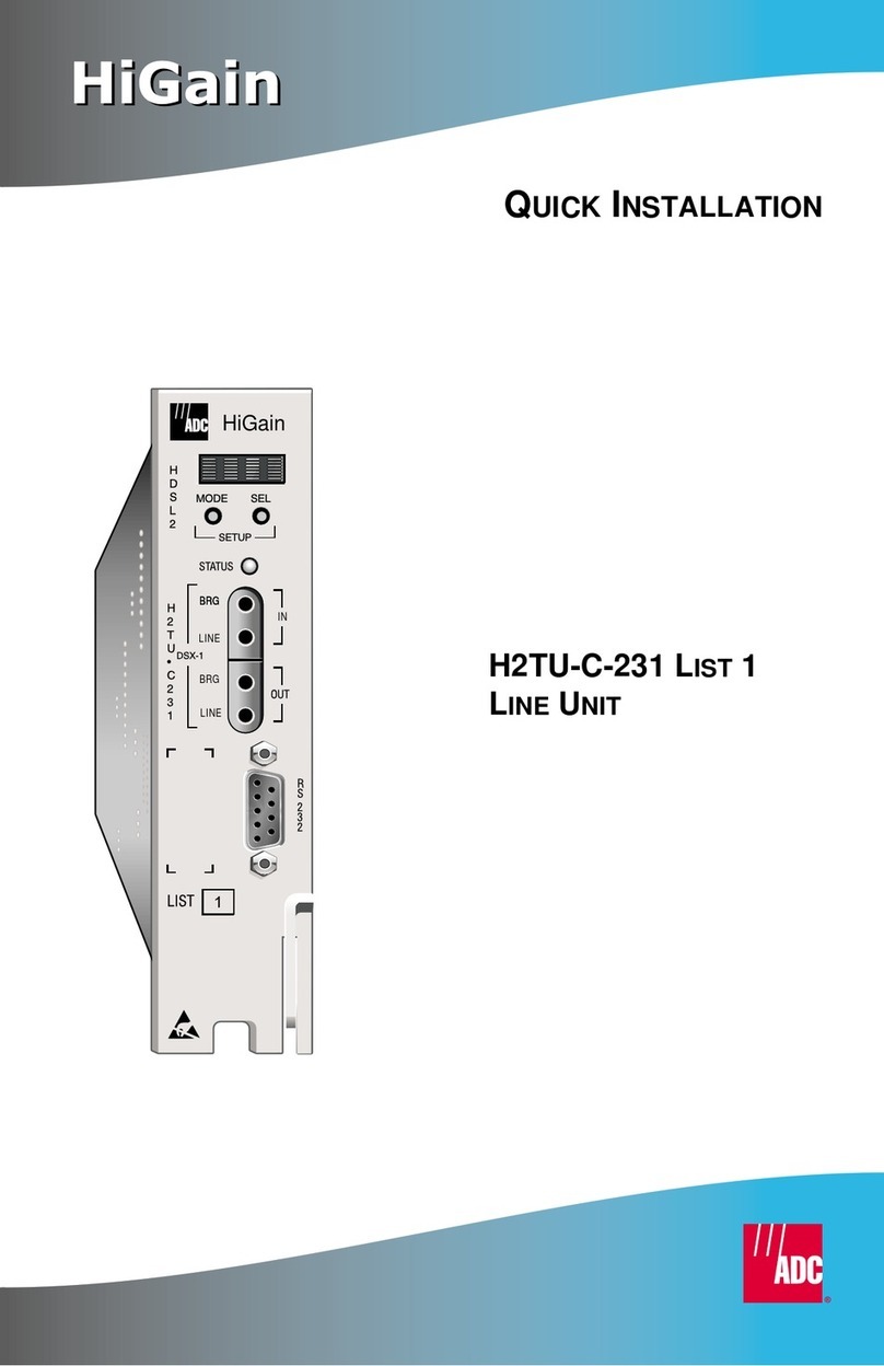
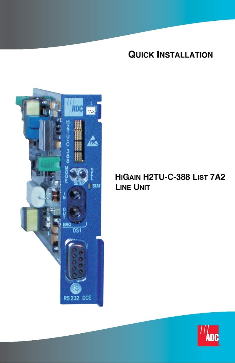
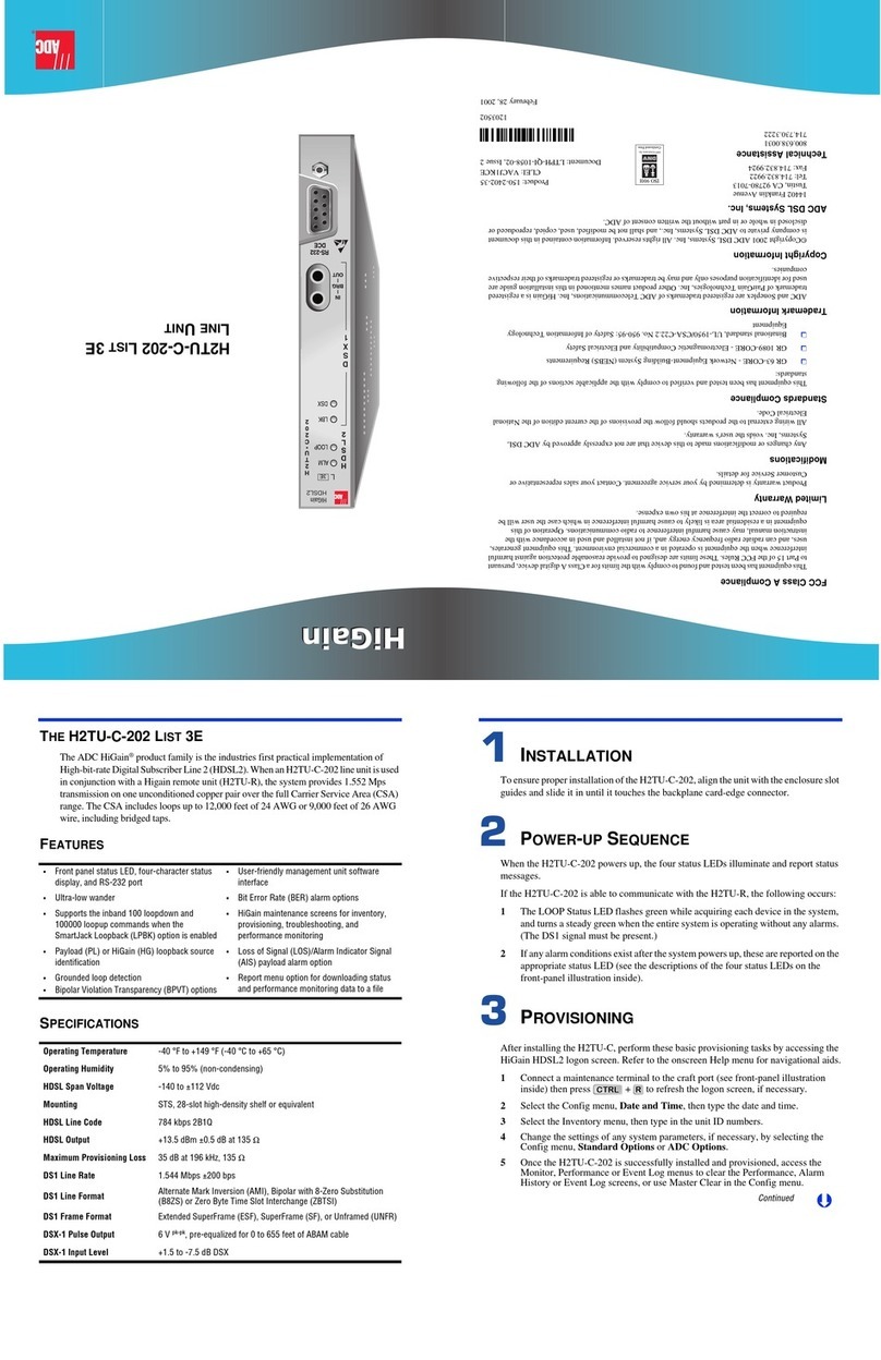
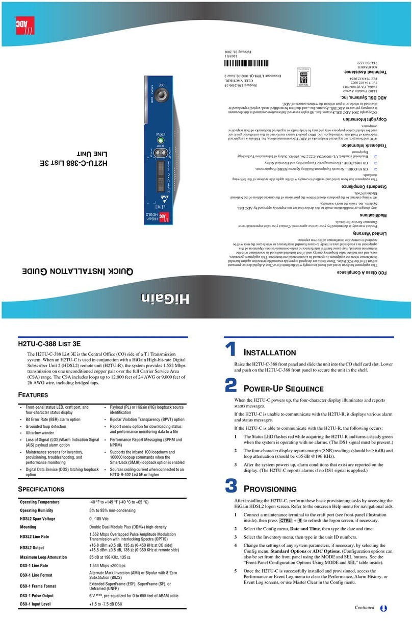
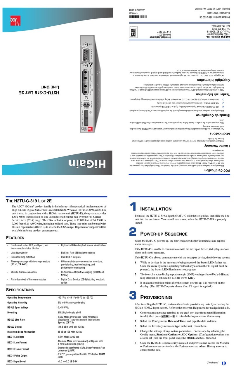
DSX-1 access jacks
List number
Status LEDs
Connect standard test equipment.
Craft port
To access all system maintenance, provisioning
and performance screens, connect a standard
DB-9 terminal cable between the serial port
on a PC and the H2TU-C craft port.
LINE Provides splitting jack access to
or from the customer or the network
multiplexer based on the DS-1 test
jack setting in the Config menu.Refer
to the user manual for more information.
MON Provides non-intrusive monitoring jack
access to (IN) and from (OUT) the
HDSL2 span at the DSX-1 interface.
Allows monitoring of the T1 payloads.
MaintenanceTerminal Modem Settings
Front Panel
Card-Edge Connector
3
4
5
6
C
D
E
F
H7
8
J
9
K
10
L
GND
HDSL2SpanTip HDSL2SpanRing
SystemAlarm** ManagementBus**
Frame GND -48Vdc BAT
Fuse Alarm*
Factory Burn-In
(Donotuse)
1
A
(IN)DSX-1TXTip DSX-1TXRing(IN)
2
B
(OUT)DSX-1 RCVTip1 DSX-1RCVRing1(OUT)
Fuse Alarm
System Alarm and Management Bus (reserved)
Normal = Floating (0 to -60 Vdc maximum)
Activated = -48Vdc, 10 mA maximum
*
**
Handle
(CLEI code and ECI bar code label on outside of handle)
9600 baud
8 data bits
No parity
1 stop bit
Hardware flow control:OFF
Terminal emulation:VT100
H0060-A
DSL
ALM
ESF / SF
YEL / GRN
B8ZS / AM
LBK
DSX / DS1
H
2
T
U
C
3
1
9
O
U
T
M
O
N
M
O
N
L
I
N
E
L
I
N
E
I
N
L
DCE
2
3
2
R
S
