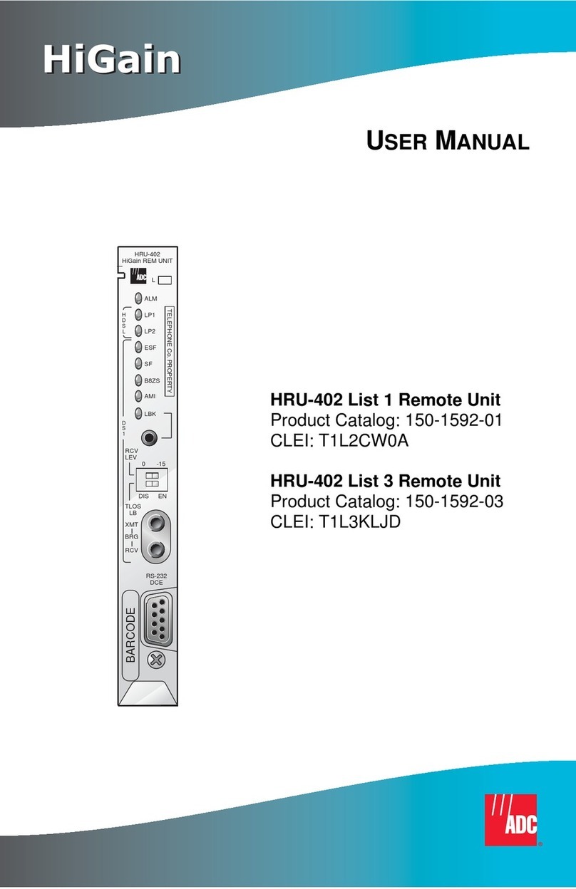
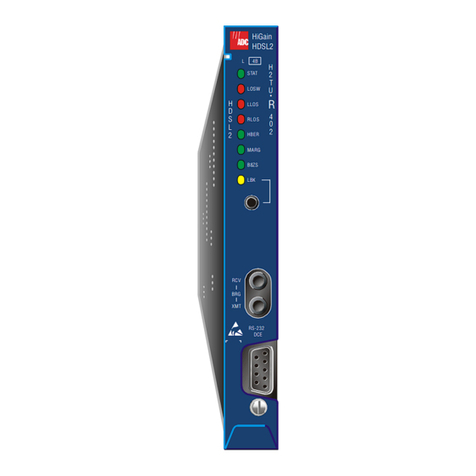
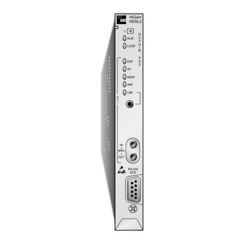
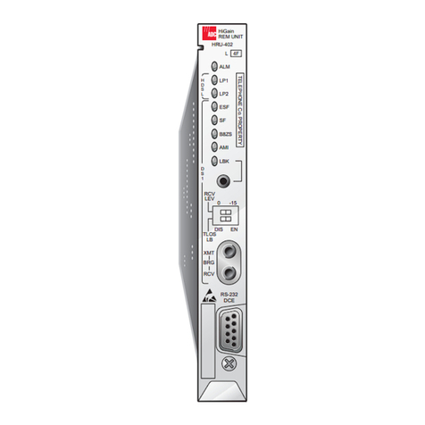
ADC HiGain HRU-402 User manual

HiGain
HiGain
USER MANUAL
HRU-402
HiGain REM UNIT
ALM
L
TELEPHONE Co. PROPERTY
LP2
ESF
SF
LP1
B8ZS
AMI
LBK
H
D
S
L
R
C
V
L
E
V
D
S
1
0-15
-7.5
-7.5/
-15
XMT
BRG
RCV
RS-232
DCE
BARCODE
1A
HRU-402 List 1A Remote Unit
Product Catalog: 150-1592-11
CLEI: T1L3KLPD

150-402-111-02
ii December 8, 1998 HRU-402 List 1A
Revision History of This Manual
Copyright
December 8, 1998
© 1998 ADC DSL Systems, Inc. All rights reserved.
Trademark Information
ADC is a registered trademark of ADC Telecommunications, Inc. HiGain is a
registered trademark of ADC DSL Systems, Inc. No right, license, or interest to such
trademarks is granted hereunder, and you agree that no such right, license, or interest
shall be asserted by you with respect to such trademark.
Other product names mentioned in this practice are used for identification purposes
only and may be trademarks or registered trademarks of their respective companies.
Disclaimer of Liability
Information containedin this document is company privateto ADC DSL Systems,Inc.,
and shall not be modified, used, copied, reproduced or disclosed in whole or in part
without the written consent of ADC.
Contents herein are current as of the date of publication. ADC reserves the right to
change the contents without prior notice. In no event shall ADC be liable for any
damages resulting from loss of data, loss of use, or loss of profits, and ADC further
disclaims any and all liability for indirect, incidental, special, consequential or other
similar damages. This disclaimer of liability applies to all products, publications and
services during and after the warranty period.
Revision Release Date Revisions Made
01 December 8, 1998 Initial Release
02 May 17, 2002 ADC rebranding

150-402-111-02 Using This Manual
HRU-402 List 1A December 8, 1998 iii
USING THIS MANUAL
Two types of messages, identified by icons, appear in the text.
UNPACK AND INSPECT YOUR SHIPMENT
Upon receipt of the equipment:
•Unpack each container and inspect the contents for signs of damage. If
theequipmenthasbeendamagedintransit,immediatelyreporttheextent
of damage to the transportation company and to ADC DSL Systems, Inc.
Order replacement equipment, if necessary.
•Check the packing list to ensure complete and accurate shipment of each
listed item. If the shipment is short or irregular, contact ADC DSL
Systems, Inc. as described in “Appendix C: Product Support” on
page 57. Ifyoumuststoretheequipmentforaprolongedperiod,store the
equipment in its original container.
Notes contain information about special circumstances.
Cautions indicate the possibility of personal injury or
equipment damage.

Unpack and Inspect Your Shipment 150-402-111-02
iv December 8, 1998 HRU-402 List 1A

150-402-111-02 Table of Contents
HRU-402 List 1A December 8, 1998 v
TABLE OF CONTENTS
Overview _______________________________________________ 1
Features.................................................................................... 2
BPVT and BER Features .........................................................3
Applications............................................................................. 4
Compatibility ___________________________________________ 5
Product Description ______________________________________ 7
Status LEDs ............................................................................. 9
Panel Circuit Board Options.................................................. 11
HLU Front Panel Display Messages......................................12
Card-edge Pinout Connector.................................................. 15
Functional Description___________________________________ 16
Installation ____________________________________________ 18
Inspecting Your Shipment ..................................................... 18
Installing HRU-402 List 1A................................................... 18
Provisioning the HRU-402________________________________ 20
Navigating the Maintenance Terminal Screens_______________ 23
Login...................................................................................... 23
System Spans ......................................................................... 26
Navigation Keys..................................................................... 27
Initializing the Maintenance Terminal Screens_______________ 28
Remote Terminal Main Menu................................................ 28
View Span Status................................................................... 30
System Settings...................................................................... 33

Table of Contents 150-402-111-02
vi December 8, 1998 HRU-402 List 1A
Additional Information on Selected Options..........................36
Remote DS-1 Alarm (RDA) Option ........................36
Alarm Pattern (ALMP) Option................................37
DS-1 Line Code “Auto” Option...............................37
Loopback Mode......................................................................38
Loopback Operation.................................................42
SmartJack Set to ENA .............................................44
SAIS Set to DIS .......................................................44
Loopback Test Procedures.......................................45
View Performance Data .........................................................46
View Performance History.....................................................49
View Alarm History...............................................................51
View System Inventory..........................................................54
Appendix A: Specifications________________________________56
Appendix B: Service and Support __________________________58
Appendix C: Abbreviations _______________________________59
Certification and Warranty _________________Inside Back Cover

150-402-111-02 List of Figures
HRU-402 List 1A December 8, 1998 vii
LIST OF FIGURES
1.Typical HiGain System .......................................................................... 1
2. Front Panel ............................................................................................ 7
3. TLOS Switch Location........................................................................ 11
4. Card-edge Pinouts ............................................................................... 15
5. HRU-402 Block Diagram.................................................................... 17
6. Installing the HRU-402 in a Remote Enclosure.................................. 19
7. DB-9 and DB-25 RS-232 I/O Interfaces............................................. 20
8. Connecting the HRU-402 to a Maintenance Terminal........................ 21
9. Remote Login Screen.......................................................................... 24
10. HiGain HLU-231 Remote Terminal Main Menu................................ 25
11. System Spans....................................................................................... 26
12. Remote Terminal Main Menu............................................................. 28
13. View Span Status Screen for Non-doubler Applications.................... 30
14. Span 1 Status Screen for Doubler Applications.................................. 31
15. System Settings Screen ....................................................................... 34
16. Loopback Menu Without Doublers..................................................... 39
17. Loopback Menu with Three Doublers.................................................40
18. HiGain System Loopbacks..................................................................42
19. Performance Data Screen Without Doublers ...................................... 47
20. Span 1 Performance Data Screen........................................................ 48
21. Performance History Screen for Non-doubler Applications............... 49
22. Span 1 Performance History Screen.................................................... 50
23. Alarm History Screen for Non-doubler Applications ......................... 51
24. Four Doublers, Span 1 Alarm History Screen..................................... 53
25. View System Inventory Screen........................................................... 55
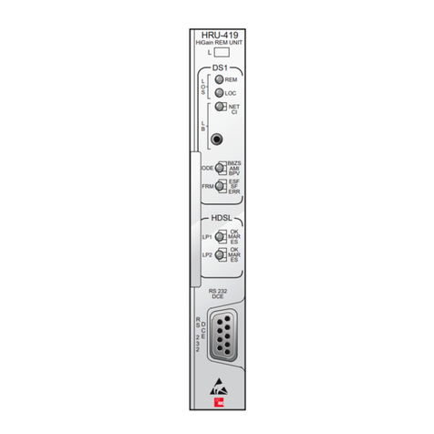
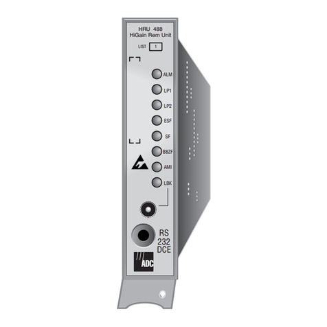
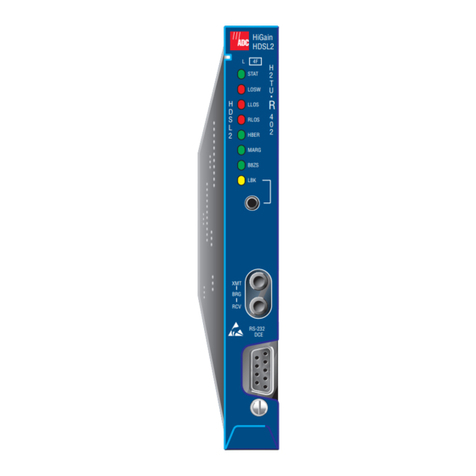
List of Tables 150-402-111-02
viii December 8, 1998 HRU-402 List 1A
LIST OF TABLES
1. HDSL Loss Over Cables........................................................................5
2. Front-panel Features..............................................................................8
3. Status LED Descriptions........................................................................9
4. Rear Unit TLOS Switch.......................................................................11
5. HLU Front Panel Display Messages....................................................12
6. Maintenance Terminal Navigational Keys..........................................27
7. Remote Terminal Menu Descriptions..................................................29
8. Span Status Fields and Descriptions....................................................32
9. System Settings Fields and Descriptions.............................................35
10. Loopback Field Messages and Descriptions........................................41
11. Alarm History Fields and Descriptions ...............................................52

150-402-111-02 Overview
HRU-402 List 1A December 8, 1998 1
OVERVIEW
This user manual describes the HiGain®Remote Unit, Model HRU-402 List
1A. This remote unit functions as the remote end of a repeaterless T1
transmission system. An HRU-402 connects either to a HiGain Line Unit
(HLU) or a HiGain Doubler Unit (HDU), creating a HiGain system that
provides 1.544 Mbps transmission on two unconditioned copper pairs over
the full Carrier Service Area (CSA) range. The HRU-402 List 1A is line
powered only.
Figure 1 shows a basic HiGain configuration for a T1 High-bit-rate Digital
Subscriber Line (HDSL) circuit. The HLU is installed at the Central Office
(CO) shelf. The HRU-402 is housed in a remote enclosure at the Customer
Premises Equipment (CPE) site. Optional HDUs provide the ability to
increase the range between the HLU and HRU to four CSA spans. The total
CSA encompasses approximately 48 kft using 19 American Wire Gauge
(AWG) wire.
Figure 1. Typical HiGain System
HRU-402
HDSL Pairs
Span 1
HDSL Pairs
Span 2
DSX-1
To CO DS-1 To
CPE
HLU
HiGain CO Shelf Remote enclosureDoubler
enclosure
HDU

Overview 150-402-111-02
2 December 8, 1998 HRU-402 List 1A
FEATURES
•Front panel with:
–Loopback Button
–Receive Level Switches
–Receive (RCV) and Transmit (XMT) Bridged (BRG) access jacks
for testing
–Digital Service Level 1 (DS-1) and HDSL status Light Emitting
Diodes (LEDs)
–Craft port access (RS-232 DB-9 connector)
•American National Standards Institute (ANSI) T1.403 DS-1 Network
Interface (NI)
•Generic and addressable repeater loopback activation codes
•Line powered
•Lightning and power cross protection on HDSL and DS-1 interfaces
•784 kbps full-duplex 2 Binary 1 Quaternary (2B1Q) HDSL transmission
on each of two pairs
•Digital Signal Level 0 (DS0) blocking
•Compatible with ADC 1 x 1 protection switching system using the
HRE-422 List 5 remote enclosure.
•Narrow 200-type mechanics (half-width 400 mechanics)
•Low power consumption
•Supports one to four span circuits
•Ultra-low wander
•Bipolar Violation Transparency (BPVT) and Bit Error Rate (BER)
options
•Remote DS-1 Alarm (RDA) option
•Alarm Pattern (ALMP) option
•Improved DS-1 Line Code auto options

150-402-111-02 Overview
HRU-402 List 1A December 8, 1998 3
BPVT AND BER FEATURES
The HRU-402 and its associated line units improve compatibility with Data
Link Control (DLC) feeder applications due to T1 Bipolar Violation
Transparency (BPVT) transmit capability between T1 interfaces. This feature
is required to support protection switching in DLC applications. Each DLC
terminal must be able to monitor the integrity of its receive T1 payload and
then switch to the protect line when the integrity of the path drops below
specific user selected limits. An essential requirement of this feature is the
need for each DLC terminal to detect BPVTs in its T1 input. Standard HDSL
systems correct input T1 BPVTs and thus prevent them from being detected
by DLC terminals to which they are connected. The HRU-402 and its
associated line units remove this limitation and become BPVT transparent by
detecting and counting input BPVTs at each end and then replicating them at
the distant end T1 output port.
In addition, the CRC errors in each direction of every HDSL loop of each
span are also counted and added in with the BPVT count to produce a Total
Error Count (TEC). TEC indicates the integrity of both the T1 and HDSL
paths. A TEC in each direction is calculated every second by adding the
number of BPVTs to the number of HDSL CRC errors in that direction. The
maximum TEC count is 12000. This TEC number is converted into BPVTs
at the distant end during the following second at a rate of 1 BPVT every 128
T1 bits up to a maximum of 12000 (Bit Error Rate[BER]=7.7x10⁻³). This
maximum rate ismore than adequate since it exceeds the maximum 10-3 BER
required by most DLC systems.
The BPVT transparencyoption is controlled by the BPVT user option, which
can be Enabled (ENA) or Disabled (DIS).
This BPVT is only available if the HRU-402 is connected to an
HLU-231 List 8x, HLU-319 List 5x, or HLU-388 List 5x.

Overview 150-402-111-02
4 December 8, 1998 HRU-402 List 1A
The BER option also uses this (BPVT/CRC) TEC to generate an alarm if
enabled. The HLU combines the one second TEC counts in both directions
for the last 60 seconds. The line unit uses this one minute Total System Error
Count (TSEC) to generate an alarm if it exceeds the selected BER threshold
of (1E-6 or 1E-7) as follows:
•BER option=1E-6. Alarm is generated if TSEC>92
•BER option=1E-7. Alarm is generated if TSEC>9
Once initiated, the alarm clears when the TSEC drops below its associated
threshold count. For irregular intermittent errors, the alarm can come and go
in intervals as short as one second. Alarms usually require the full 60 seconds
or longer to clear depending on the frequency of the transient errors. This
BER option is present in any HiGain 98 line unit circuit.
APPLICATIONS
HRU-402 List 1A provides a cost-effective and easy-to-deploy method for
delivering T1 service over two metallic pairs. Conventional, in-line T1
repeaters, cable pair conditioning, pair separation, and bridged tap removal
are not required.
The HRU-402 List 1A:
•operates with any number of T1, Plain Old Telephone Service (POTS),
or other HiGain systems sharing the same cable binder group.
•can be used with customers requiring T1 service on a temporary or
permanent basis.
•provides a means of quickly deploying service in advance of fiber-optic
transmission systems.
•is easily installed allowing service to be provided within hours. Fiber
optic systems can be installed and cut-over from the installed HiGain
system. The installed HiGain system can then be easily removed and
utilized elsewhere.

150-402-111-02 Compatibility
HRU-402 List 1A December 8, 1998 5
Each cable pair loop has less than 35 dB of loss at 196 kHz with 135Ωdriving
and terminating impedances. Table 1 provides a guide for the loss of various
cable gauges at 196 kHz and 135Ω. Table 1 applies to the HDSL cable pairs
between the HLU, HRU, and HDU modules. Without specific insertion loss
measurement data, add 3 dB for each bridged tap and 1 dB for each cable
gauge change.
COMPATIBILITY
The HRU-402 List 1A can be used with all HiGain doublers and doubler
compatible line units for two or three span applications. The HRU-402 List
1A can also be used with the following line and doubler units for four span
applications:
•HLU-231 List 8x
•HLU-319 List 5x
•HLU-388 List 5x
•HDU-409
•HDU-407
•HDU-404
Table 1. HDSL Loss Over Cables
Cable Gauge Loss at 196 kHz (dB/kft) Ωper kft
26 AWG (0.4 mm) 3.88 83
24 AWG (0.51 mm) 2.84 52
22 AWG (0.61 mm) 2.18 32
19 AWG (0.91 mm) 1.54 16

Compatibility 150-402-111-02
6 December 8, 1998 HRU-402 List 1A
The HRU-402 mounts in the following types of shelves (indoor use):
•HRE-420 (single-wide, single mount)
•HRE-422 (double-wide, double mount)
•HRE-425 (12-slot wall or rack mount)
•HRE-427 (seven-slot wall or rack mount)
•200 Mechanics type shelves
•400 Mechanics type shelves
For outdoor applications, the HRU-402 mounts in the following shelves:
•HRE-450 (single-slot)
•HRE-454 (four-slot)

150-402-111-02 Product Description
HRU-402 List 1A December 8, 1998 7
PRODUCT DESCRIPTION
The HRU-402 List 1A front panel is shown is Figure 2. The front panel
components are described in Table 2.
Figure 2. Front Panel
Alarm LED
Loopback LED
CLEI/ECI Bar code label
Loopback control button
DS-1 receive attenuation switches
RS-232 Craft port
Extraction handle
DS-1 transmit and receive
bridging jacks
HDSL LEDs
DS-1 framing LEDs
DS-1 Line code LEDs
HRU-402
HiGain REM UNIT
ALM
L
TELEPHONE Co. PROPERTY
LP2
ESF
SF
LP1
B8ZS
AMI
LBK
H
D
S
L
R
C
V
L
E
V
D
S
1
0-7.5/
-15
-7.5 -15
XMT
BRG
RCV
RS-232
DCE
1A
Configuration number label
(inside handle)

Product Description 150-402-111-02
8 December 8, 1998 HRU-402 List 1A
Table 2. Front-panel Features
Name Function
Status LEDs See Table 3 on page 9 for status descriptions.
Loopback (LPBK)
Control button
Pressing the button for five seconds activates a remote loopback
towards the Network at the Remote unit Loopback (NREM). The
unit can be unlooped by either pressing the LPBK control button
again for five seconds or by the standard loopdown coded
messages. Also provides the ability to loopdown other
loopbacks.(a)
(a) Any existing loopbacks are terminated before NREM loopback is activated.
DS-1 Receive (RCV)
Level (LEV) switches
Sets DS-1 RCV. Line build out level output toward the Customer
Interface (CI).
0Sets the DS-1 receive level toward the CI to 0 dB.(b)
(b) Default Setting.
-7.5/-15 Sets the DS-1 receive level toward the CI according to the switch
setting below.
-7.5 Sets the DS-1 receive level toward the CI to -7.5 dB if switch above
is set to -7.5/-15.
-15 Sets the DS-1 receive level toward the CI to -15 dB if switch above
is set to -7.5/-15.
DS-1 XMT and RCV
Bridging jacks
Provides bridging test and monitor access jacks to the CPE DS-1
interface. Provides both monitor and test access capability.
See Figure 5 on page 17 for circuit details.
RS-232 Craft port Provides bidirectional communication between the unit and an
external maintenance terminal through an RS-232 interface to
allow configuration and performance monitoring through the
Maintenance Terminal menus. See the section “Connecting to a
Terminal Emulator” on page 20 for operating procedures.
CLEI/ECI Bar code
label
Contains human-readable Common Language Equipment
Identifier (CLEI) code number and Equipment Catalog Item (ECI)
bar code number.
Configuration
number label
Contains either a five-digit or six-digit warranty configuration
number or a standalone two or three-digit configuration number as
follows:
Digit 1 = Last digit of shipment year
Digits 2 and 3 = Shipment month
Digits 4, 5 or 6 = Configuration number
Extraction handle Handle used to remove the HRU-402 from the remote enclosure.

150-402-111-02 Product Description
HRU-402 List 1A December 8, 1998 9
STATUS LEDS
Table 3 describes the functions of the Status LEDs on the front panel.
Table 3. Status LED Descriptions
LED Status Indicates
Alarm (ALM) LED Shows alarm states for remote and local Loss of Signal (LOS).
Solid red Indicates a LOS condition at HRU T1 input.
Blinking red Indicates a LOS condition at HLU T1 input.
HDSL LEDs Displays HDSL Loop 1 (LP1) and Loop 2 (LP2) conditions.
Solid green Indicates HDSL loop is in sync.
Blinking green 1 time
per second
Indicates the HDSL loop is trying to acquire sync.
Blinking green 4
times per second
Indicates a margin alarm condition on the HDSL loop.
Blinking green 10
times per second
Indicates a Cycle Redundancy Check (CRC) error on the HDSL
loop.
OFF Indicates no activity on the HDSL loop.
DS-1 Framing (FRM)
LEDs (ESF and SF)
Indications for framing patterns.(a) If DS-1 framing is set to
Unframed (or THRU), the LEDs will not light.
ESF LED = Solid
green
Indicates Extended Super Frame (ESF). The light blinks one time
per second when a frame error is indicated.
SF LED = Solid green Indicates Super Frame (SF). The light blinks twice per .5 second
when a frame error is indicated.
OFF Indicates unframed or no signal
Continued

Product Description 150-402-111-02
10 December 8, 1998 HRU-402 List 1A
DS-1 Code LEDs
(B8ZS and AMI)
Indications for DS-1 code options.(a)
B8ZS LED = Solid
green
(DS-1 Code
Option=B8ZS)
Indicates that the DS-1 line code option is set to B8ZS. The light
blinks one time per second when a string of excessive zeros is
detected.
B8ZS LED = Solid
green
(DS-1 Code
Option=Auto(b))
Indicates the DS-1 line code is being detected as B8ZS.
AMI LED = Solid
green
(DS-1 Code
Option=AMI)
Indicates that the user DS-1 line code option is set to AMI. The
solid green light does not indicate the actual DS-1 line code being
received, which may be Alternate Mark Inversion (AMI) or B8ZS.
This light blinks one time per second when a Bipolar Violation
(BPV) is detected.
AMI LED = Solid
green
(DS-1 Code
Option=Auto(b))
Indicates the DS-1 line code is being detected as AMI.
Loopback (LPBK)
LED
Shows loopback states to and from the network and to and from
the Customer Interface (CI) and an ARMED condition.
Solid yellow Indicates Network Remote Loopback (NREM), SMJK, or TLOS.
Blinking 1 per second Indicates Customer Local Loopback (CLOC) loopback state.
Blinking 4 per second Indicates the HRU is in an ARMED state.
(a) If DS-1 signals are not detected, the ESF, SF, Bipolar with 8-Zero Substitution (B8ZS)
and Alternate Mark Inversion (AMI) LEDs will not light.
(b) Auto DS-1 code option not available when attached to a HLU-231 L8D, HLU-319 L5D,
or HLU-388 L5D.
Table 3. Status LED Descriptions (Continued)
LED Status Indicates

150-402-111-02 Product Description
HRU-402 List 1A December 8, 1998 11
PANEL CIRCUIT BOARD OPTIONS
HRU-402 List 1A has user options that are set before you install the unit into
a shelf or an enclosure. The DS-1 RCV LEV configuration switches are
located on the front panel (see Figure 2 on page 7). The RCV LEV options
are defined in Table 2 on page 8. The TLOS switch adjacent to the card-edge
connector is shown in Figure 3. The TLOS options are defined in Table 4.
Figure 3. TLOS Switch Location
Table 4. Rear Unit TLOS Switch
TLOS - Rear Unit Switch
Disable (a) (down)
(a) Default setting.
Disables the TLOS option. When an RLOS occurs, AIS
will be sent toward the network.
Enable (up) Enables the TLOS option. When an RLOS occurs, the
HRU-402 List 1A initiates a loop back toward the
network.

Product Description 150-402-111-02
12 December 8, 1998 HRU-402 List 1A
HLU FRONT PANEL DISPLAY MESSAGES
Table 5 lists and describes the messages that may appear on the HLU line unit
front panel display while the HRU-402 is connected to the HLU-231 List 8x,
HLU-319 List 5x, or HLU-388 List 5x.
Table 5. HLU Front Panel Display Messages
Message Name Description
CREM Customer
Remote
Loopback
Signal from customer is looped back to customer at the
HLU.
NLOC Network Local
Loopback
DSX signal is looped back to DSX at the HLU.
CLOC Customer Local
Loopback
Signal from customer is looped back to customer at the
HRU.
NREM Network Remote
Loopback
DSX signal is looped back to DSX at the HRU.
SMJK Remote
SmartJack
Loopback
Signal from DSX is looped back to the DSX at the HRU by
the HRU SmartJack.
TLOS Transmit Loss Of
Signal
HRU is in a logic loopback state caused by a loss of its T1
input from the CI, if enabled at the HRU by its TLOS switch
option.
FERR Framing Bit Error
Occurred
Framing bit error occurred at the T1 input to the HLU.
LBPV Local Bipolar
Violation
A bipolar violation occurred at the T1 input to the HLU.
SIG 1 or
SIG 2
Signal 1 or
Signal 2
The HLU and HRU or first doubler transceivers are trying
to establish contact with each other on Loops 1 or 2 of
Span 1.
S2L1 or
S2L2
Signal 2 Loop 1
or Loop 2
The first doubler and either HRU or second doubler
transceivers are trying to establish contact with each
other on loops 1 or 2 of Span 2.
S3L1 or
S3L2
Signal 3 Loop 1
or Loop 2
The second doubler and either HRU or third doubler
transceivers are trying to establish contact with each
other on loops 1 or 2 of Span 3.
Continued
Other manuals for HiGain HRU-402
4
This manual suits for next models
1
Table of contents
Other ADC Remote Control manuals

ADC
ADC HiGain HRU-402 Original operating instructions

ADC
ADC HiGain HRU-402 Original operating instructions

ADC
ADC H4TU-R-402 List 1 Original operating instructions

ADC
ADC H2TU-R-402 List 5F Original operating instructions

ADC
ADC HiGain HRU-402 User manual

ADC
ADC HiGain H2TU-R-402 List 1B Original operating instructions

ADC
ADC HRU-419 HiGain User manual

ADC
ADC HiGain H2TU-R-402 List 4B Original operating instructions

ADC
ADC HiGain HRU-488 Original operating instructions

ADC
ADC HiGain H2TU-R-402 List 4F User manual