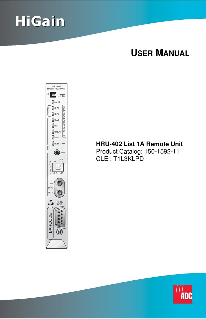
ADC HRU-419 HiGain User manual

USER MANUAL
HRU-419
HiGain REM UNIT
L
DS1
REM
L
O
S
L
B
LOC
LP1
CODE
LP2
FRM
NET
CI
HDSL
B8ZS
AMI
BPV
OK
MAR
ES
RS 232
DCE
OK
MAR
ES
ESF
SF
ERR
R
S
2
3
2
D
C
E
HRU-419 HiGain Remote Unit
Product Catalog: 150-419-100-03
CLEI: T1L2CCLAAA

150-419-100-03>
ii September 25, 1998 HRU-419 List 1
Revision History of This Manual
To order copies of this manual, use document catalog number
150-419-100-03.
Copyright
September 25, 1998
© 2003 ADC DSL Systems, Inc. All rights reserved.
Trademark Information
ADC is a registered trademark and WorldDSL is a trademark of ADC
Telecommunications, Inc. HiGain is a registered trademark of ADC DSL Systems, Inc.
No right, license, or interest to such trademarks is granted hereunder, and you agree
that no such right, license, or interest shall be asserted by you with respect to such
trademark.
Other product names mentioned in this document are used for identification purposes
only and may be trademarks or registered trademarks of their respective companies.
Disclaimer of Liability
Information containedin this document iscompany private toADC DSL Systems, Inc.,
and shall not be modified, used, copied, reproduced or disclosed in whole or in part
without the written consent of ADC.
Contents herein are current as of the date of publication. ADC reserves the right to
change the contents without prior notice. In no event shall ADC be liable for any
damages resulting from loss of data, loss of use, or loss of profits, and ADC further
disclaims any and all liability for indirect, incidental, special, consequential or other
similar damages. This disclaimer of liability applies to all products, publications and
services during and after the warranty period.
Issue Release Date Revisions Made
1July 21, 1997 Initial release
2September 25, 1998 Update revision
3February 25, 2003 ADC rebrand
150-419-100-03> Using This Manual
HRU-419 List 1 September 25, 1998 iii
USING THIS MANUAL
The following conventions are used in this manual:
•Monospace type indicates screen text.
•Keys you press are indicated by small icons such as or . Key
combinations to be pressed simultaneously are indicated with a plus sign
as follows: + .
•Items you select are in bold.
The following types of messages are conveyed by icons:
For a list of abbreviations used in this document, refer to “Appendix B-
Abbreviations” on page 51.
Notes provide information about special circumstances.
Genenral cautions indicate the possibility of personal injury,
product failure, or equipment damage if instructions are
ignored or not completely followed.
An Electrostatic Discharge (ESD) caution indicates that a
deviceorassemblyissusceptibletodamagefromelectrostatic
discharge.
An electrical shock caution indicates the presence of a
dangerous level of electrical power and the potential for
serious personal injury or equipment damage.
A laser caution indicates the potential for permanent eye
damage or blindness due to direct exposure to laser beams.
YENTER
CTRL ESC

Unpack and Inspect Your Shipment 150-419-100-03>
iv September 25, 1998 HRU-419 List 1
UNPACK AND INSPECT YOUR SHIPMENT
Upon receipt of the equipment:
•Unpack each container and inspect the contents for signs of damage. If
the equipment has beendamaged in transit,immediatelyreport theextent
of damage to the transportation company and to ADC DSL Systems, Inc.
Order replacement equipment, if necessary.
•Check the packing list to ensure complete and accurate shipment of each
listed item. If the shipment is short or irregular, contact ADC DSL
Systems, Inc. as described in “Appendix C - Product Support” on
page 53.Ifyoumust store theequipmentfora prolongedperiod,storethe
equipment in its original container.

150-419-100-03, Revision 03
HRU-419 List 1 September 25, 1998 v
TABLE OF CONTENTS
Overview _______________________________________________ 1
Features________________________________________________ 2
Applications ____________________________________________ 3
Front Panel...............................................................................4
Compatibility ........................................................................... 9
Local and Line Powering....................................................... 10
Three-Span Line Powering .................................................... 11
Installation ____________________________________________ 11
Inspecting Your Shipment ..................................................... 11
Installing the HRU-419.......................................................... 12
Connecting to a Maintenance Terminal................................. 13
Card edge pinout connector................................................... 15
The HRU-419 Circuit Board.................................................. 16
The Maintenance and Remote Terminal................................ 19
Maintenance and Remote Terminal....................................... 23
View Span Status..................................................... 24
Set Clock ................................................................. 30
System Settings ....................................................... 31
View Performance Data .......................................... 33
View Performance History...................................... 37
View Alarm History................................................ 39
Remote Logoff......................................................... 40
Loopbacks _____________________________________________ 41
Loopbacks Toward the Network............................................ 43
Loopbacks Toward the Customer.......................................... 43
SmartJack (SMJK) Loopback................................................ 44

150-419-100-03, Revision 03
vi September 25, 1998 HRU-419 List 1
SAIS Set to ENA....................................................................44
SAIS Set to DIS......................................................................45
Loss of Sync Word (LOSW) Conditions ...............................46
HAIS Set to 1 Loop................................................................46
HAIS Set to 2 Loops ..............................................................46
Using the Loopback (LB) Button...........................................46
Appendix A- Technical Specifications _______________________48
Functional Description ...........................................................49
Operational Capabilities.........................................................49
Appendix B- Abbreviations________________________________51
Appendix C - Product Support_____________________________53

150-419-100-03, Revision 03
HRU-419 List 1 September 25, 1998 vii
LIST OF FIGURES
Figure 1. Typical HiGain System........................................................... 1
Figure 2. HRU-419 Front Panel.............................................................4
Figure 3. HRU-419 Installed in a Card Shelf....................................... 12
Figure 4. DB-9 RS-232 I/O.................................................................. 13
Figure 5. Connecting the HRU-419 to a Maintenance Terminal......... 14
Figure 6. HRU-419 Card Edge Connector Pinout................................15
Figure 7. HRU-419 Circuit Board Connections for User Options....... 17
Figure 8. Maintenance Terminal Main Menu ......................................20
Figure 9. Remote Terminal Log in Screen........................................... 21
Figure 10. Remote Terminal Main Menu............................................. 21
Figure 11. View Span Status Screen for Non-Doubler Applications... 24
Figure 12. Span 3 Status for Two Doublers Application ..................... 26
Figure 13. Set Clock Menu................................................................... 30
Figure 14. System Settings Screen....................................................... 31
Figure 15. Performance Data Screen for Non-Doubler Applicatiions. 33
Figure 16. Span 1 Perfromance Data Screen........................................ 34
Figure 17. Span 2 Perfromance Data Screen........................................ 35
Figure 18. 7 Day History Screen for Non-Doubler Applications......... 37
Figure 19. 7 Day History Span 2.......................................................... 38
Figure 20. Performance History Screen for Non-doubler Applications...
39
Figure 21. HRU-419 Loopbacks.......................................................... 42
Figure 22. HRU-419 Block Diagram................................................... 50

150-419-100-03, Revision 03
viii September 25, 1998 HRU-419 List 1
LIST OF TABLES
Table 1. HDSL Loss Over Cables ..........................................................3
Table 2. HRU-419 Front Panel Components..........................................5
Table 3. HRU-419 Front Panel Component Functions...........................6
Table 4. Reading the HRU-419 Front Panel LEDs ................................7
Table 5. HRU-419 Shelf and Mounting Hardware Compatibility..........9
Table 6. HRU-419 Card Edge Connector Pinouts................................16
Table 7. Maintenance and Remote Terminal Navigational Keys.........22
Table 8. Maintenance and Remote Terminal Menus............................23
Table 9. Span Status Fields and Descriptions.......................................27
Table 10. HRU-419 Alarm Field Messages and Descriptions..............28
Table 11. HRU-419 Loopback Field Messages and Descriptions........29
Table 12. System Settings Fields and Descriptions..............................32
Table 13. Alarm History Fields and Descriptions ................................40

150-419-100-03> Overview
HRU-419 List 1 September 25, 1998 1
OVERVIEW
The ADC®HiGain®HRU-419 List 1 Remote Unit (HRU), is the remote end
of a repeaterless T1 transmission system. When used with any HiGain Line
Unit (HLU) or HiGain Doubler Unit (HDU) the HiGain system provides
1.544 Mbps on two unconditioned copper pairs over the full Carrier Service
Area (CSA) range. The HRU-419 mounts on a STS-3192 High Density shelf
or in an equivalent remote enclosure manufactured by ADC
Telecommunications.
A basic HiGain configuration is shown in Figure 1 for a T1 High-bit-rate
Digital Subscriber Line (HDSL) circuit. The HLU is installed at the Central
Office (CO) shelf and the HRU is housed in a remote enclosure at the
Customer Premises Equipment (CPE). Optional HDUs provide the ability to
double or even triple the distance range for customer applications located
outside the CSA.
The HiGain system uses HDSL transmission technology as recommended by
Bellcore TA-TSY-001210. The HRU-419 complies with: ANSI T1E1.4,
T1.403-1989 and 1995, and T1E1.4/92-00R2R technical standards and
recommendations. The system also complies with TR-TSY-000063 Network
Equipment Building System (NEBS) Generic Equipment requirements,
TR-TSY-000499 Transport System Generic Requirements (TSGR) common
requirements, and TR-TSY-000312 Functional Criteria for DSX-1 Interface
Connection.
Figure 1. Typical HiGain System
HRU-419
HDSL Pair
Span 1
HDSL Pair
Span 2
DSX-1
To CO DS1 T
o
CPE
HLU
HiGain CO Shelf Remote enclosureDoubler
enclosure
HDU

Features 150-419-100-03>
2 September 25, 1998 HRU-419 List 1
FEATURES
•DS1 and HDSL status LEDs
•HDSL margin threshold indicator
•RS-232 Craft port for connection to a maintenance terminal
•ANSI T1.403 DS1 Customer Interface (CI)
•Generic and addressable repeater loopback activation codes
•Metallic SmartJack loopback.
•Provisioning switches for Customer Premises Equipment (CPE) current,
Receive (RCV) Level and XMT LOS (TLOS) initiated loopback and
Alarm Indication Signal (AIS)
•Line or local power options
•Optional sealing current
•Supports three-span line powering
•CPE current monitor test points available on PC board
•Lightning and power cross protection on HDSL and DS1 interfaces
•784 kbps full-duplex 2-Bits–1–Quaternary (2B1Q) HDSL Transmission
on two pairs
•DS0 blocking
•Conforms to High-density 3192 STS mechanics
The HRU-419 is an HRU-419 List 8 unit for STS-3192 High-density
mechanics. However, the HRU-419 List 1 does not support the following
HRU-419 List 8 features:
•Front Panel DS1 Test Jacks
•Protection switching
•Front panel CPE current monitor

150-419-100-03> Applications
HRU-419 List 1 September 25, 1998 3
APPLICATIONS
The HiGain system provides a cost-effective, easy-to-deploy method for
delivering T1 service over a single metallic pair. Conventional in-line T1
repeaters are not required. Cable pair conditioning, pair separation and
bridged tap removal are not required.
General guidelines require that the loop has less than 35 dB of loss at
196 kHz, with 135 Ωdriving and terminating impedances. Table 1 provides a
guide for the loss of various cable gauges at 196 kHz and 135 Ω. The table
applies to the HDSL cable pairs between the HLU, HRU and HDU modules.
Without specific insertion loss measurement data, add 3 dB for each bridged
tap and 1 dB for each cable gauge change.
The HiGain systems can:
•operate with any number of other T1, Plain Old Telephone Service
(POTS), or other HiGain systems sharing the same cable binder group.
•be used with customers requiring T1 service on a temporary or
permanent basis.
•provide a means of quickly deploying service in advance of fiber-optic
transmission systems.
•easily be installed allowing service to be provided within hours. Fiber
optic systems can be installed at a leisurely pace and cut-over from the
installed HiGain system when convenient to do so. The installed HiGain
system can then be easily removed and utilized elsewhere.
Table 1. HDSL Loss Over Cables
Cable Gauge Loss at 196 kHz (dB/kft) Ohms per kft
26/0.4 mm 3.88 83
24/0.51 mm 2.84 52
22/0.61 mm 2.18 32
19/0.91 mm 1.54 16

Applications 150-419-100-03>
4 September 25, 1998 HRU-419 List 1
FRONT PANEL
Figure 2 shows the HRU-419 front panel components. Table 3 describes the
functions of the front panel components and Table 4 describes the status
conditions indicated by the LEDs.
Figure 2. HRU-419 Front Panel
HRU-419
HiGain REM UNIT
L
DS1
REM
L
O
S
L
B
LOC
LP1
CODE
LP2
FRM
NET
CI
HDSL
B8ZS
AMI
BPV
OK
MAR
ES
RS 232
DCE
OK
MAR
ES
ESF
SF
ERR
R
S
2
3
2
D
C
E
Loopback (LB) LEDs
Code LEDs
Framing (FRM) LEDs
LOS LEDs
HDSL LEDs
RS-232 connector
Loopback button
Card handle

150-419-100-03> Applications
HRU-419 List 1 September 25, 1998 5
Table 2. HRU-419 Front Panel Components
Name Function
LOS LEDs Show Loss of Signal (LOS) alarm states (see Table 3 on page 6 and
Table 4 on page 7).
Loopback
LEDs
Show loopback states (see Table 3 on page 6 and
Table 4 on page 7).
Loopback
button
Provides the ability to perform loopback test procedures (see “Using the
Loopback (LB) Button” on page 46.
Code
LEDs
Provide indications for line code options (see Table 3 on page 6 and
Table 4 on page 7).
Framing
LEDs
Provides indications for framing patterns (see Table 3 on page 6 and
Table 4 on page 7).
HDSL
LEDs
Display HDSL Loop 1 and Loop 2 Conditions (see Table 3 on page 6 and
Table 4 on page 7).
Card
Handle
Used to insert and remove the HRU-419 from the card shelf.
RS-232
Craft port
Configured as data circuit-terminating equipment (DCE) which allows you
to control the HRU-419 through a maintenance terminal (or a PC with
terminal emulation software).

Applications 150-419-100-03>
6 September 25, 1998 HRU-419 List 1
Table 3. HRU-419 Front Panel Component Functions
Name Function
LOS LEDs Remote and Local Loss Of Signal (LOS).
REM LOS Displays remote (REM) LOS.
LOC LOS Displays local (LOC) LOS.
LB LEDs Loopback to/from the NET (Network) and to/from the CI.
NET Displays NET loopback state.
CI Displays CI loopback state.
Loopback
(LB)
Activates the remote unit metallic loopback state by pressing the button for
five (5) seconds. The unit can be unlooped by either pressing the button
again for five seconds or through the standard loopdown coded messages.
CODE LEDs Indications for line code options.
B8ZS Indicates that the DS1 line code option is set to Bidirectional 8-Zero
Substitution (B8ZS).
AMI Indicates that the user DS1 line code option is set to Alternate Mark
Inversion (AMI).
BPV Indicates that a Bipolar Violation (BPV) is received at the remote’s DS1
input.
FRM LEDs Indications for framing patterns.
ESF Displays ESF framing.
SF Displays SF framing.
ERR Framing error.
HDSL LEDs Display HDSL Loop 1 and Loop 2 conditions
LP1 (Loop 1)
OK Display synchronization state for HDSL Loop 1.
MAR Indicates that the Signal-to-Noise (S/N) margin has dropped below the
margin threshold value.
ES Indicates at least one HDSL Cyclic Redundancy Check (CRC) error is
detected from the upstream module.
LP2 (Loop 2)
OK Displays synchronization state for HDSL Loop 2.
MAR Indicates that the S/N margin has dropped below the margin threshold
value.
ES Indicates at least one HDSL CRC error is detected from the upstream
module.
RS-232 Craft
port
Provides bi-directional communication between the unit and an external
maintenance terminal through an RS-232 interface to allow configuration
and performance monitoring through the Maintenance Terminal menus.

150-419-100-03> Applications
HRU-419 List 1 September 25, 1998 7
Table 4. Reading the HRU-419 Front Panel LEDs
Name Description
REM LOS
On
Lights red when the LOS is detected at the T1 input to the remote
HLU unit. This condition causes the HRU to transmit the AIS pattern
towards the CPE.
Off Normal transmission of data.
LOC LOS
On Lights red when the LOS is detected at the T1 input to the local HRU.
This condition causes an AIS-CI signal to be transmitted towards the
customer and an AIS-CI signal to be sent to the DSX-1 from the
HLU. This state is not sent to the HLU and does not register an LOS
ALRM condition.
Off Normal transmission of data.
NET
On Lights green when the HRU is in a loopback state in which the signal
from the NET is being looped back to the NET.
Off No NET loopbacks are active.
CI
On Lights yellow when the HRU is in a loopback state when the signal
from the CI is being looped back to the CI.
Off No CI loopbacks are active.
B8ZS Lights green when DS1 line code option set to B8ZS. If the user DS1
line code option is set to Auto, LED indicates that the code of the
DS1 signal being received at the HRUs DS1 input is B8ZS.
AMI Lights yellow when DS1 line code option set to AMI. If the user DS1
line code option is set to Auto, LED indicates that the code of the
DS1 signal being received at the HRUs DS1 input is AMI.
BPV Blinks red every time a BPV, other than those associated with a B8ZS
code, is received at the HRU DS1 input.
ESF Blinks green when the framing pattern of the signal being received
at the HRU DS1 input is ESF.
SF Blinks yellow when the framing pattern of the signal being received
at the HRU DS1 input is SF.
ERR Lights red when a DS1 frame error has occurred.

Applications 150-419-100-03>
8 September 25, 1998 HRU-419 List 1
LP1
OK
Blinks green when HDSL Loop 1 is synchronizing with the HLU.
Lights green when HDSL Loop 1 is synchronized and ready to
receive and transmit data.
MAR Blinks yellow when a problem in Loop 1 (doubler applications only)
of the HDSL cable pairs that are non-adjacent to the HRU. Blinking
once per second indicates a Loss of Sync Word (LOSW) problem in
Span all ones Loop 1 HDSL pair between the HLU and doubler.
Blinking twice per second indicates a LOSW problem in Span two’s
Loop 1 HDSL pair between the first and second doublers.
ES Blinks red every second when one HDSL CRC error is detected on
Loop 1 from the upstream module.
LP2
OK
Blinks green when HDSL Loop 2 is synchronizing with the HLU.
Lights green when HDSL Loop 2 is synchronized and ready to
receive and transmit data.
MAR Blinks yellow when a problem in Loop 2 (doubler applications only)
of the HDSL cable pairs that are non-adjacent to the HRU. Blinking
once per second indicates a LOSW problem in Span two’s Loop 2
HDSL pair between the HLU and doubler. Blinking twice per second
indicates a LOSW problem in Span 2s Loop 2 HDSL pair between the
first and second doublers.
ES Blinks red every second in which at least one HDSL CRC error is
detected on Loop 2 from the upstream module.
Table 4. Reading the HRU-419 Front Panel LEDs (Cont.)
Name Description

150-419-100-03> Applications
HRU-419 List 1 September 25, 1998 9
COMPATIBILITY
The HRU-419 is compatible with the following shelves and mounting
hardware listed in Table 5.
Table 5. HRU-419 Shelf and Mounting Hardware Compatibility
Manufacturer Description
Charles Industries # 3192 (28 slot connectorized)
Charles Industries # 3192-9F Alarm Card
Larus # 1185 (28 slot connectorized)
Larus # 1184 Alarm Card
Charles Industries #3192-WR (28 slot wire wrap)
Charles Industries #343-00 (12-14 slot wire wrap)
Charles Industries #319-02 (22 slot connectorized)
Charles Industries #319-04 (22 slot wire wrap)
Charles Industries #340-00 (9-11 slot wire wrap)
ADC HMS-318 22-slot, 19-inch shelf
ADC HHS-319 Three-slot, 19-inch horizontal shelf
ADC HMS-317 28-slot, 23-inch shelf
ADC HMS-308 Eight-slot remote enclosure
ADC HCS-402 Two-slot portable enclosure

Applications 150-419-100-03>
10 September 25, 1998 HRU-419 List 1
LOCAL AND LINE POWERING
The HRU-419 unit can be line or local powered. The unit always uses the
local -48 V power source if it is present, and defaults to line power in the
absence of local power. List 6 and higher versions of the HLU-231, and all
versions of the HLU-319 and HLU-388, and versions 6.4 and above of the
HLU-231 List 1, 2, 3, 3A and 4 units automatically turn off their line power
supply when connected to a locally powered HRU-419. The earlier versions
of the HLU-231 (Lists 1, 2, 3, 3A and 4) must first have their PWRF user
option set to disable to work properly with a locally powered HRU-419.
When locally powered, the HRU-419 also provides from 20 mA (long loop)
to 30 mA (short loop) of simplex sealing current towards all versions of the
HLU over the 2 HDSL pairs. Jumper JP1, shown in Figure 7 on page 17,
allows the sealing current to be enabled or disabled
(see“The HRU-419 Circuit Board” on page 16).
Reversed loops are indicated by a CHREV message in the "Alarms" field of
the Span Status screen shown in “View Span Status” on page 24.
The simplex sealing current is not compatible with the List 1, 2, or 3
HDU-451 doublers. These doublers block the flow of simplexed sealing
current. The HDU-451 List 4, the HDU-437 or the HDU-439 must be used
with the HRU-419 to provide a path through which the simplexed sealing
current can flow.
If local power is lost to the HRU in a non-doubler or a single doubler circuit,
the system will lose sync. When the HLU or HDU attempts to re-acquire
sync, it will detect that the HRU is not locally powered and apply line power
to it.
This simplexed sealing current is polarity sensitive and will
not flow if the two HDSL loops adjacent to the HRU are
reversed.

150-419-100-03> Installation
HRU-419 List 1 September 25, 1998 11
THREE-SPAN LINE POWERING
The HRU-419 can be used with the following line units and doublers for
three-span line powering applications:
•Line units: HLU-231 List 7D and 7B. HLU-431 List 1D
•Doublers: HDU-437 List 1, HDU-439 List 1
For further information see the HiGain Mini Doublers, Model HDU-437 and
HDU-439, technical practice.
INSTALLATION
This section provides information on inspection and installation of the
HRU-419.
INSPECTING YOUR SHIPMENT
When you receive the equipment, inspect it for signs of damage. If the
equipment has been damaged in transit, immediately report the extent of
damage to the transportation company and to ADC.
Your shipment should consist of:
•One HRU-419 List 1
•This document
Three-span line powered circuits must have no more than
2000 Ωof total loop resistance.

Installation 150-419-100-03>
12 September 25, 1998 HRU-419 List 1
INSTALLING THE HRU-419
The HRU-419 mounts in an STS-3192 High Density shelf or in equivalent
card shelves manufactured by ADC Telecommunications (HHS-319,
HMS-317 and HMS-308).
To install the HRU-419 (Figure 3), Set the user options as described in the
following:
1Slide the HRU-419 into the card guides for the desired slot, then push the
unit into the enclosure until it touches the backplane card edge connector.
Figure 3. HRU-419 Installed in a Card Shelf
2Push the unit into the card edge connector until it is entirely within the
card guide, indicating that the unit is properly seated.
HRU-419
Card shelf
Table of contents
Other ADC Remote Control manuals

ADC
ADC HiGain H2TU-R-402 List 4F User manual

ADC
ADC HiGain HRU-488 Original operating instructions

ADC
ADC HiGain HRU-402 User manual

ADC
ADC H2TU-R-402 List 5F Original operating instructions

ADC
ADC PG-PLUS Instructions for use

ADC
ADC HiGain H2TU-R-402 List 4B Original operating instructions

ADC
ADC HiGain H2TU-R-402 List 1B Original operating instructions

ADC
ADC HiGain HRU-402 Original operating instructions

ADC
ADC HiGain HRU-402 Original operating instructions

ADC
ADC H4TU-R-402 List 1 Original operating instructions