VERIFICATION
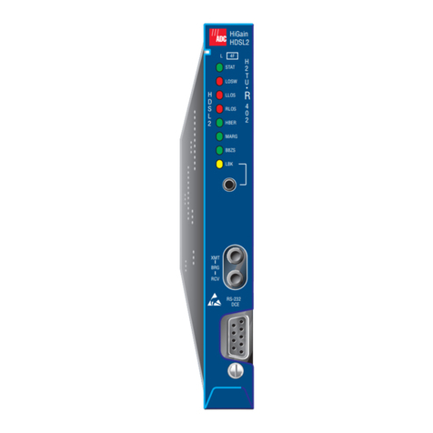
After the H4TU-R is installed, verify that it is operating properly by monitoring the status
LEDs on the front panel.
REACH
The maximum reach of the H4TU-R-402 is based on a maximum signal loss over span 1 of
47 dB@196 kHz and a a maximum signal loss over spans 2 and 3 of 43 dB@196 kHz. The
following table lists the reach as a function of cable gauge.
LOGGING ON TO THE MAIN MENU
The H4TU-R-402 supports local and remote logon through a maintenance terminal (VT100
or a PC running VT100 terminal-emulation software). In HDSL4 systems equipped with the
H4TU-C, the maintenance terminal connects to the H4TU-C front panel craft port. In
HDSL4 systems equipped with the H4LXC, the maintenance terminal connects to the front
panel craft port of the Shelf Control Unit (SCU) controlling the H4LXC.
Remote login creates menus and screens for the H4TU-R that are identical to those viewed
at the H4TU-C or H4LXC. Once logged on, you can view system settings and inventory,
initiate loopbacks, monitor performance, and provision the circuit.
To log on and access the H4TU-C Remote Terminal Main Menu screens:
1Press the several times to display the Remote Login screen.
2Press the key to view the Maintenance Terminal Screen.The Remote Terminal
Main Menu items are replications of the line unit screens. Depending on the line unit
attached to the H4TU-R-402, remote provisioning may be available.
To log on and access the H4LXC Main Menu screens:
1Press the key twice to display the Logon screen.
2Type the assigned logon ID in the Enter Username field. If a logon ID is not assigned,
type SONEPLEX (default), then press .
3Type the assigned password at the Enter Password field. If a password is not assigned,
type SONEPLEX1.
4Press the key to view the Main Menu screen.
LOOPBACK TESTING
Initiate loopback testing from the maintenance terminal menus or by using in-band codes.
The inband codes shown below can be sent by a test set. For more information, refer to the
applicable H4TU-C or H4LXC line unit user manual.
H4TU-C Configured Systems
H4LXC Configured Systems
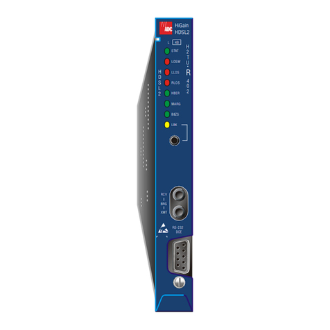
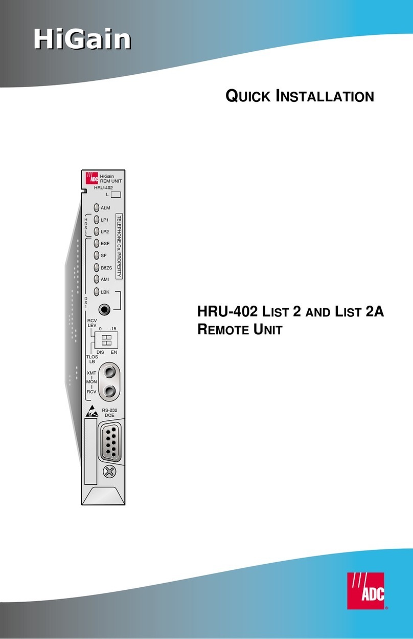
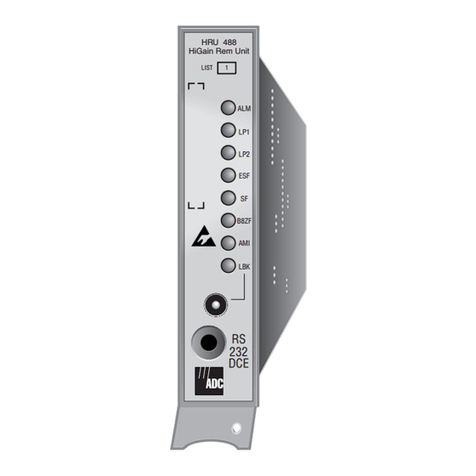
Status LED Descriptions
LED Status Description
ALM LED (red) Indicates alarm state for remote and local Loss ofSignal (LOS).
Solid Loss of Signal (LOS) condition at the T1 input of the HRU.
Blinking LOS condition at the T1 input of the line unit.
LP1 and LP2 LEDs (green) Indicates HDSL4 Loop 1 (LP1) and Loop 2 (LP2) condition.
Solid Solid green = HDSL4 loop is in sync.
Blinking Once per second = HDSL4 loop is trying to acquire sync.
4 times per second = Margin alarm condition on HDSL4 loop.
10 times per second = Cyclical Redundancy Check (CRC) error on HDSL4 loop.
OFF No activity on HDSL4 loop.
ESF and SF LEDs (a) (green)
(a) If DS1 signals are not detected, the ESF, SF, B8ZS, and AMI LEDs do not illuminate.
Indicates framing patterns.
ESF Solid Extended Super Frame (ESF)
f
raming pattern.
SF Solid Super Frame (SF) framing pattern.
ESF and SF Blinking Once per second = Frame error detected.
ESF and SF OFF Unframed or no signal.
B8ZS and AMI LEDs(a) (b)
(green)
(b) When optioned for AUTO LINE CODE, these LEDs indicate when an AMI or B8ZS DS1 code is detected.
Indicates DS1 code options.
B8ZS LED Solid DS1 line code option is set to Bipolar with 8-Zero Substitution (B8ZS).
Blinking Once per second = String of excessive zeros detected.
AMI LED Solid User DS1 line code option is set to Alternate Mark Inversion (AMI).
Blinking Once per second = Bipolar Violation (BPV) detected.
LBK LED (yellow) Shows loopback states to and from the network and to and from the Customer
Interface (CI).
Solid Network Remote (NREM), SmartJack (SMJK), or Transmit Loss of Signal
(TLOS) loopback.
Blinking Once per second = Customer Local (CLOC) loopback state.
4 times per second = HRU in Armed state.
HDSL4 Maximum Reach Chart
Cable Gauge Reach (kft.) Loop Attenuation
(dB per kft.) Insertion Loss
(a)
@196 kHz (dB per kft.)
(a) Insertion Loss = 1.38 times loop attenuation
Ω
/
kft.
Span 1 Spans 2 and 3
26 (0.4 mm) 12 11.0 2.8 3.88 83
24 (0.51 mm) 16 15.0 2.0 2.84 52
22 (0.61 mm) 21 20.6 1.6 2.18 32
19 (0.91 mm) 29 27.8 1.1 1.54 16
The H4TU-C can be provisioned at the H4TU-C front panel or through the
maintenance terminal screens at the HMU managing the H4TU-C. The H4LXC is
provisioned through the maintenance terminal screens at the SCU managing the
H4LXC. For more information on the maintenance terminal screens, refer to the
applicable H4TU-C or H4LXC line unit user manual.
H4TU-C GNLB Loopback Commands
Loopback In-Band Code Description
NLOC 1111000 DSX-1 signal is looped back to the network at the H4TU-C.
NREM 1110000 DSX-1 signal is looped back to the network at the H4TU-R.
SMJK 11000 DSX-1 signal is looped back to the network at the H4TU-R
SmartJack module.
CREM 1111110 DS1 signal from customer is looped back to the customer at the
H4TU-C.
CLOC 1111100 DS1 signal from customer is looped back to the customer at the
H4TU-R.
Loopdown 11100 Deactivates any of the above loopbacks.
H4LXC Default Codes for Programmable Loopback Operations
Operation Default Binary Code Description
Loopup H4LXC 1101 0011 1101 0011
Activates a loopback at the specified unit.Unit goes
from Armed to loopup state.
Loopup H4D1 1100 0111 0100 0001
Loopup H4D2 1100 0111 0101 0100
Loopup H4TU-R 1100 0111 0100 0010
Loopdown (all units) 1001 0011 0110 0011 Deactivatestheloopback.Unit goesfromloopupstate
to Armed state.
Loopup time-out disable 1101 0101 1101 0110 Disables loopup time-out. Loopback stays active until
deactivation or disarm code is received.
SPACEBAR
ENTER
ENTER
ENTER
ENTER
Network Customer
Premises
H4TU-C H4D1 H4D2 H4TU-R
*TLOS
NLOC NDU1 NDU2
CREM CDU1 CDU2 CLOC
1111000 110000 111000 NREM
1110000 1111100
111100 1111101111110
11000
SMJK
DS1
DSX-1
*When enabled,TLOS is an automatic loopback
that occurs with an LOS at the remote DS1 input.
HDSL DS1
D1S Signal
to CPE
DS1 Signal
from CPE
DS1 HDSL
DS1 Signal
from
Network
DS1 Signal
from CPE
H4LXC H4TU-R
HDSL HDSL
HDSL4
loop
HDSL HDSL
235
14
68
7
H4D H4D
HDSL4 HDSL4
loop loop
27
25
23
21
19
17
15
13
11
9
7
3
5
1
DS1 Tip
Card-EdgeConnector
DS1 Ring
HDSL4 Ring1
HDSL4 Tip1
Factory Use Only
Factory Use Only
Factory Use Only
Protection Switch Power
DS1 Ring1
Circuit Ground
(-)
(+)
HDSL4 Ring
XMT
RCV
HDSL4 Tip
DS1 Tip1
Chassis Ground*
28
26
24
22
20
18
16
14
12
10
8
4
6
2
55
53
51
49
47
45
43
41
39
37
35
32 31
56
54
52
50
48
46
44
42
40
38
36
34
30
33
29
Note: Active pins are highlighted in black.
*Chassis Ground may be tied to earth ground per local practice.
Protection Switch Control
Chassis Ground*
-48 Vdc Local Power (List 1)
HDSL4
Loop1
HDSL4
Loop2
ALM
L
LP2
ESF
SF
LP1
B8ZS
AMI
LBK
D
S
1
IN
BRG
OUT
RS-232
DCE
Craft port provisioning
To access all system maintenance, provisioning
and performance screens, connect a standard
9-pin terminal cable between the serial port on a PC
and the H4TU-R craft port.
Loopback control button
LPWR switch
Pressing the button for 5 seconds activates
a remote loopback towards the network, called a
Network Remote Loopback (NREM).
The unit can be looped down by
either pressing the LPBK control button again
for 5 seconds or by the standard loopdown inband
messages.
Any
existing loopback is terminated before NREM
is activated.
Located on circuit board next to card-edge connector.
for more information.See “1 Installation,” step 2,
Modem settings:
1200-9600 baud
8 data bits
No parity
1 stop bit
Hardware flow control:OFF
Terminal emulation:VT100
Alarm LED
Loopback LED
CLEI/ECI bar code label
Extraction handle
HDSL LEDs
DS1 framing LEDs
DS1 code LEDs
List number
DS1 transmit (IN) and receive (OUT)
bridging jacks
For non-intrusive test access to the DS1 signal received by (IN)
and transmitted from (OUT) the Customer Premises Equipment
(CPE). Allows testing of signals to and from the CPE.
HDSL4
H
4
T
U
R
4
0
2
