ADCA FLT User manual
VA L STEAM
ADCA
IMI FLT20.015 E 00.22
FLT
INSTALLATION AND MAINTENANCE INSTRUCTIONS
FLOAT AND THERMOSTATIC
STEAM TRAPS
ADCA
We reserve the right to change the design and material of this product without notice.
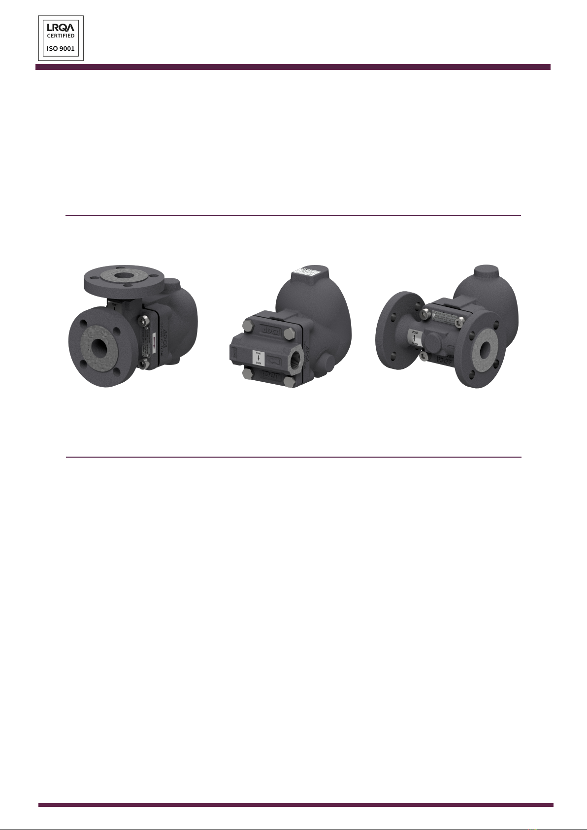
FLT20 / FLT21 / FLT25
FLT30 / FLT31 / FLT35
FLT40 / FLT41 / FLT45

VA L STEAM
ADCA
IMI FLT20.015 E 00.22
ADCA
GENERAL INFORMATION
• These instructions must be carefully read before performing any work involving
VALSTEAM ADCA products. Failure to observe these instructions may result in
hazardous situations.
• These instructions describe the entire life cycle of the product. Keep them in a
location that is accessible to every user and make these instructions available to
every new owner of the product.
• Current regional and plant safety regulations must be considered and followed
during installation, operation, and maintenance work.
• The images shown in these instructions are for illustration purposes only.
• For the problems that cannot be solved with the help of these instructions, please
contact VALSTEAM ADCA or its representative.
VALSTEAM ADCA ENGINEERING S.A
Zona Ind.da Guia
Pav.14 - Brejo
3105-467 Guia, Pombal
PORTUGAL
We reserve the right to change the design and material of this product without notice.

VA L STEAM
ADCA
IMI FLT20.015 E 00.22
ADCA
CONTENT
1. SAFETY INFORMATION 5
1.1. Explanation of symbols 5
1.2. Intended use 5
1.3. Qualication of personnel 6
1.4. Personal protective equipment 6
1.5. The system 6
1.6. ATEX 7
1.7. General safety notes 7
2. PRODUCT INFORMATION 9
2.1. Principle of operation 9
2.2. Certication 10
2.3. Product identication 11
2.4. Technical data 11
3. TRANSPORT, STORAGE AND PACKAGING 12
4. INSTALLATION 13
4.1. Preparation for installation 13
4.2. Changing ow direction 15
4.3. Installation procedure 17
5. START-UP 17
5.1. Preparation for start-up 17
5.2. Start-up procedure 18
6. OPERATION 19
6.1. Operating the BDV and HVV units 19
6.2. Operating the FLL 19
7. SHUTDOWN 20
7.1. Shutdown procedure 20
8. PARTS LIST 21
9. MAINTENANCE 23
9.1. Maintenance procedure 23
9.2. Cleaning/replacing the mechanism assembly 23
9.3. Replacing the oat 24
9.4. Fitting the retrot BDV, HVV, AFZ and VB21M units 25
9.5. Replacing the FLL oat lifting lever 25
9.6. Tightening torques 26

VA L STEAM
ADCA
IMI FLT20.015 E 00.22
ADCA
CONTENT
10. TROUBLESHOOTING 26
11. DISPOSAL 27
12. RETURNING PRODUCTS 27
VA L STEAM
ADCA
IMI FLT20.015 E 00.22
ADCA
5
1. SAFETY INFORMATION
1.1. Explanation of symbols
Hazardous situation which, if not avoided by applying the correct preventive
measures, will result in fatal or serious injury and/or considerable damage to
property.
DANGER
Hazardous situation which, if not avoided by applying the correct preventive
measures, could result in fatal or serious injury and/or considerable damage
to property.
WARNING
Hazardous situation which, if not avoided by applying the correct preventive
measures, could result in moderately severe or minor injury.
CAUTION
Situation which, if not avoided, can result in property damage or product
malfunction.
NOTICE
Indicates additional information, tips and recommendations.
NOTE
1.2. Intended use
Refer to the markings on the device, such as nameplate and laser markings, Information
Sheet (IS) and these Installation and Maintenance Instructions (IMI) to check that the
product was designed for the intended use and meets the specications used for sizing
and selection. This includes checking application, material suitability, process medium,
pressure and temperature as well as their respective limiting values.
VALSTEAM ADCA does not assume any responsibility for damage resulting from
inappropriate use of the product, damage caused by external stresses or any other
external factors. Correct installation of the product is the full responsibility of the contractor.

VA L STEAM
ADCA
IMI FLT20.015 E 00.22
ADCA
6
Inappropriate use of the product is any use other than the one described in this chapter.
Inappropriate use also includes:
• Use of spare parts which are not genuine;
• Performance of maintenance work not described in these instructions;
• Use outside the limits dened by the accessories connected to the product.
• Unauthorized modications to the product.
If the product is to be used for an application or with a uid other than the one it was
designed for, contact VALSTEAM ADCA.
1.3. Qualication of personnel
Handling, installation, operation and maintenance work must be carried out by fully
trained and qualied personnel, capable of judging the work which they are assigned
to perform and recognizing potentially hazardous situations. They should be trained to
properly use this product according to these Installation and Maintenance Instructions.
Where a formal “Permits to Work” system is implemented in the plant it must be complied
with.
1.4. Personal protective equipment
Personal protective equipment should always be worn during work in order to protect
against hazards posed by e.g. the process medium, dangerous temperatures, noise,
falling or projected objects, working at height. These equipment includes a helmet, safety
glasses, safety harness, protective clothes, safety shoes, hearing protection, etc.
Always assess whether you or others in your vicinity require any protective
equipment. When in doubt check with the plant’s health & safety responsible
personnel for details on required protective equipment.
NOTE
1.5. The system
The complete system should be assessed as well as every action (e.g. closing of shut-
o valves, disconnection of the power supply) to ensure this will not bring additional risk
to personnel or property.
Dangerous actions that can result in a hazardous situation include isolation of protective
devices such as safety valve, vents, vacuum relief valves, disconnection of electric safety
devices, sensors and alarms.

VA L STEAM
ADCA
IMI FLT20.015 E 00.22
ADCA
7
1.6. ATEX
If the product is in the scope of the ATEX 2014/34/EU directive and as such bears the Ex
marking, consult its specic Additional Instructions for use in Potentially Explosive Areas
(IMI EX). In such cases, handling, installation, operation and maintenance work must
only be performed by personnel qualied and authorized to work in potentially explosive
areas.
1.7. General safety notes
RISK OF BURSTING IN PRESSURE EQUIPMENT
Valves, ancillaries and pipelines are pressure equipment. Working above
their operating limits or improper opening can lead to component bursting.
• Observe the maximum operating limits of the product and check if they are
lower than those of the system in which it is being installed. Check the product
Information Sheet (IS).
• Install a safety device.
• Before starting any work on the product, depressurize it and cool or heat it up
to ambient temperature. This also applies to the line in which it is tted.
• Drain the process medium from the product and all the relevant plant sections.
DANGER
RISK OF BURNS
Depending on the operating conditions, products and pipelines may get very
hot or cold and cause burn injuries.
• Do not touch the product while it is hot or cold, allowing it rstly to cool down
or heat up.
• Wear protective clothing and safety gloves during working operation.
• Thermally insulate tubes and product’s as a preventive measure.
RISK OF INJURY CAUSED BY FLUID ATTACK ON PRODUCTS
MATERIALS
The product must only be used with mediums that do not attack the materials
of the product (body, gaskets, seals). Otherwise, leaks may occur, and hot
and/or hazardous uid can escape.
• Do not use the product with mediums other than the ones it was designed for.
Check section 1.2 - Intended Use.
• Prevent medium contamination.
WARNING

VA L STEAM
ADCA
IMI FLT20.015 E 00.22
ADCA
8
RISK OF INJURY CAUSED BY UNDER TIGHTENED PRODUCT OR
ITS COMPONENTS
Excessively low tightening torques may cause medium to escape or and/or
components to be projected at high speed which may result in a hazardous
situation depending on the medium, chemical properties and/or its operating
conditions.
• Do not loosen any screw while the equipment is pressurized.
• Observe the specied tightening torques on these Installation and Maintenance
Instructions. If the relevant torque value is not mentioned contact VALSTEAM
ADCA.
RISK OF HEARING LOSS
Depending on the operating conditions, the product may generate loud
noises.
• Wear hearing protection when in the vicinity of the product.
RISK OF INJURY AS A RESULT OF ILLEGIBLE INFORMATION
Important information written in the product nameplate, markings and warning
signs may wear overtime or get illegible due to e.g. dirt accumulation, resulting
in hazardous situations and personal injury or property damage.
• Keep nameplates, markings and warning signs in a legible state, replacing
when illegible, missing or damaged.
WARNING
RISK OF INJURY DUE TO RESIDUAL PROCESS MEDIUM
Direct contact with dangerous process medium may lead to personal injury,
e.g. smoke inhalation and chemical burns.
• Drain the process medium from the product and all the relevant plant sections.
• Wear protective clothing, safety gloves, mask, and eye protection.
RISK OF INJURY DUE TO IMPROPER HANDLING
Manual handling (e.g. lifting, carrying, pushing, pulling) of large and/or heavy
products may result in personal injury.
• Assess the risk associated with the handling task.
• Use adequate handling methods and appropriate auxiliary handling equipment.
CAUTION
VA L STEAM
ADCA
IMI FLT20.015 E 00.22
ADCA
9
RISK OF PRODUCT DAMAGE DUE TO EXCESSIVELY HIGH
TIGHTENING TORQUES
High tightening torques may lead to premature wearing of product components.
• Observe the specied tightening torques on these Installation and Maintenance
Instructions. If the relevant torque value is not mentioned contact VALSTEAM
ADCA.
NOTICE
2. PRODUCT INFORMATION
The ADCA FLT20, FLT21 and FLT25 (SG iron), FLT30, FLT31 and FLT35 (carbon steel)
and FLT40, FLT41 and FLT45 (stainless steel) are oat and thermostatic steam traps
with integral air vent designed for modulating discharge of condensate and air venting,
ensuring maximum system heat transfer.
Typical applications include unit heaters, heat exchangers, dryers, jacketed vessels and
other applications where continuous discharge is essential.
These steam traps can be installed in horizontal or vertical pipelines and are available
with inline or angled variants to suit system design.
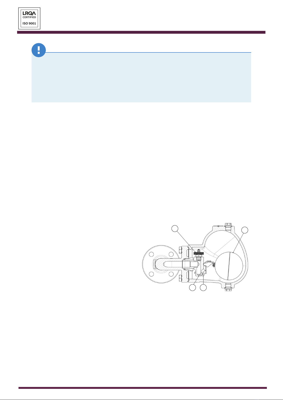
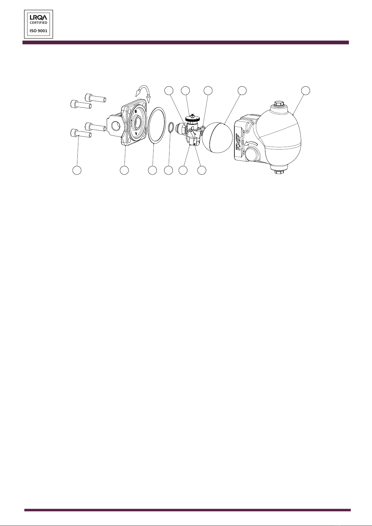
2.1. Principle of operation
A oat (8) opens or closes the valve seat
(4), by moving a ball (6) via a simple
lever mechanism according with the
condensate level inside the steam trap,
changing its position in relation to the
seat. Condensate discharge and opening
of the equipment is proportional to the
movement of the oat. As the oat rises,
so does the discharge capacity. Discharge
is modulating and does not interfere with
automatic controls, if tted.
Air venting is ensured by a thermostatic
air vent (9) located in the steam space above the condensate level. After releasing the
initial air, it remains closed until air and other non-condensable gases accumulate during
normal operation and cause it to open by reducing the temperature of the air/steam
mixture. The thermostatic air vent oers the added benet of increasing condensate
capacity on cold start-up.
The steam trap can be supplied without air vent.
9
4
Fig. 1
6
8

VA L STEAM
ADCA
IMI FLT20.015 E 00.22
ADCA
10
Thermostatic capsule air vents are available on request in alternative to the standard
bimetallic air vent.
The steam trap can be supplied with a variety of options, most of which can also be
retrotted in case the steam trap has been supplied with the optional top and bottom
cover connections.
The steam lock release (SLR) consists in a needle valve integrated in the steam trap
body. Its aperture is tunned manually, with a screwdriver, to allow constant bleeding of
steam, just enough to prevent steam locking. This option is not retrottable.
The oat lifting lever (FLL) is used to manually open the steam trap main valve, to drain
its content or to check the current oat position. This option is not retrottable.
The hand vent valve (HVV) is a retrottable option which can be installed on the top
cover connection. It is used for manual venting and/or depressurization.
The blowdown valve (BDV) is a retrottable option which can be installed on the bottom
cover connection. It is used as a manual drain and/or depressurization.
The anti-freeze device (AFZ) is a retrottable option which can be installed on the
bottom cover connection. It is used for automatic discharge of condensate after system
shutdown to prevent it from freezing inside the steam trap. The valve consists in a simple
mechanism with a spring and a stainless steel ball. The spring force keeps the valve
open as long as the medium pressure is below approximately 0,3 bar, at which point the
medium pressure pushes the ball against the seat and closes the valve.
The vacuum breaker (VB21M) is a retrottable option which can be installed on the
top cover connection. It is used to protect plant and process equipment, such as heat
exchangers, against vacuum condition. A stainless steel ball remains on the seat of the
vacuum breaker when the system is under positive pressure. The ball lifts o the seat in
case of vacuum formation, and air is drawn into the equipment “breaking” the vacuum.
2.2. Certication
This product has been specically designed for use with liquids and gases which are
in Group 2 of the European PED – 2014/68/EU Pressure Equipment Directive and it
complies with its requirements.
FLT20, FLT21 and FLT25 – CE MARKING – GROUP 2 (PED – European Directive)
PN 16 Category
All sizes SEP
FLT30, FLT31, FLT40 and FLT41 – CE MARKING – GROUP 2 (PED – European Directive)
PN 40 Category
All sizes SEP

VA L STEAM
ADCA
IMI FLT20.015 E 00.22
ADCA
11
FLT35 and FLT45 – CE MARKING – GROUP 2 (PED – European Directive)
CLASS 150 PN 40 Category
All sizes – SEP
– All sizes 1 (CE marked)
If the product falls within category SEP it must not be CE marked, unless
other directives are applicable.
NOTE
This product is not in the scope of the ATEX 2014/34/EU directive as it does not have its
own potential ignition source. Personnel responsible for the plant installation must assess
the risks caused by static electricity and take the necessary precautionary measures to
prevent static charge. These measures include e.g. connection of the product to the
equipotential bonding system.
2.3. Product identication
The following items are indicated on the product nameplate or directly on its body:
• Manufacturer
• Product model (e.g. FLT30)
• Pressure rating (e.g. PN 40)
• Nominal size (e.g. NPS 3/4")
• Max. dierential pressure (e.g. DP: 4,5 bar)
• Max. operating temperature (e.g. TMO: 250 ºC)
• Max. operating pressure (e.g. PMO: 32 bar)
• Min. admissible temperature (e.g. -10 ºC)
• Max. admissible temperature (e.g. TMA: 300 ºC @ 27,6 bar)
• Max. admissible pressure (e.g. PMA: 37,1 bar @ 100 ºC)
• Flow direction (indicated by an arrow)
• Serial number and year of manufacturing (e.g. Reg.:17483/19)
• CE Marking (when applicable – see section 2.2 – Certication)
• EX Marking (when applicable e.g. EX h IIB T6…T3 Gb – see section 2.2 –
Certication)
2.4. Technical data
For technical data including dimensions, materials, limiting conditions and versions refer
to the product respective Information Sheet (IS).

VA L STEAM
ADCA
IMI FLT20.015 E 00.22
ADCA
12
3. TRANSPORT, STORAGE AND PACKAGING
RISK DUE TO FALLING LOADS
Loads may tip or fall over resulting in demage to property, serious injury or
death.
• Use suitable equipment when moving or lifting suspended loads.
• Make sure no one is standing below the suspended load.
WARNING
RISK OF INJURY DUE TO IMPROPER HANDLING
Manual handling (e.g. lifting, carrying, pushing, pulling) of large and/or heavy
products may result in personal injury such as back injury.
• Assess the risk associated with the handling task.
• Use adequate handling methods and appropriate auxiliary handling equipment.
CAUTION
RISK OF PRODUCT DAMAGE DUE TO IMPROPER STORAGE
• Do not remove any packaging or protective covers until immediately before
installation at the site.
• Store the product in a solid base in a dry, cool and dust-free environment.
• Until its installation, protect it from the weather, dirt, corrosive atmospheres and
other harmful inuences.
RISK OF PRODUCT DAMAGE DUE TO LONG TERM STORAGE
Some product components may deteriorate with time (e.g. valve packings,
seals).
• Do not store the product for more than 12 months.
• If for any reason the product must be stored for longer periods of time contact
VALSTEAM ADCA.
NOTICE
Products are individually wrapped in plastic lm, thermo shrinkable plastic and/or stored
in a cardboard box as they leave VALSTEAM ADCA. Avoid removing packaging and any
protective cover until immediately before installing the product at the site.
If the transport packaging has any shipping damage contact VALSTEAM
ADCA or its representative.
NOTE

VA L STEAM
ADCA
IMI FLT20.015 E 00.22
ADCA
13
Before storing and transporting the product protect it from impacts and mechanical
damage, paying special care with sealing surfaces and other fragile parts.
If the corrosion protection (paint and other surface coatings) of the product is
damaged during transport or other handling procedures repair it immediately.
NOTE
4. INSTALLATION
Before performing any installation work, refer to section 1 – Safety information.
RISK OF INJURY DUE TO INSUFFICIENT SUPPORT
DURING INSTALLATION
Insucient support of the product during installation may cause it to fall and
cause personal injury.
• Ensure the product is safely held in place during installation.
• Wear protective safety shoes.
WARNING
RISK OF PRODUCT DAMAGE DUE TO STRESS
The product is not intended to withstand external stresses that may be
inducted by the system to which it is being connected to.
• Make sure that the connected pipe does not subject the body to any stress
(forces or torques) during installation and operation.
• Do not use the product as an elevation point.
NOTICE
4.1. Preparation for installation
Before installation, make sure the following conditions are met:
• The installation area has easy access and the product is to be installed in a position
where operation and maintenance work can be performed safely.
• The product will be installed with proper support and free of any stresses that can
be induced by the system due to e.g. pipe expansions. The necessary precautions
are recommended during system design.
• The pipeline where the product will be installed is designed in such a way that it
takes into account the weight of the product. The pipeline may require support on

VA L STEAM
ADCA
IMI FLT20.015 E 00.22
ADCA
14
both sides next to the product, particularly if its size and weight are considerable
and especially if vibrations are to be expected in the system.
• The product is not damaged.
• Make sure all the necessary materials and tools are readily available during
installation work.
• Referring to this Installation and Maintenance Instructions (IMI), Information Sheet
(IS) and nameplate, check that the product is suitable for the intended installation:
temperature, medium, pressure, temperature, etc. – see section 1.2 – Intended
use.
• Check that there are no foreign bodies inside the pipelines and ancillaries, ushing
may be necessary. These should be thoroughly cleaned.
• Check any mounted pressure gauges and make sure these function properly.
• An additional ADCA pipeline strainer or lter may be necessary to install upstream
of the steam trap in some applications, preventing solid particles in the process
medium from damaging it.
• A balance pipe can be connected to the optional top cover connection. This is
useful in some applications, particularly when the steam trap is not tted with an air
vent. The cross section of the balance pipe must be at least DN 8 - 1/4".
• The pipelines are layed out with a gradient so that condensate is free to fall towards
the steam trap.
Assembly Drawings (AD) with assembly details and parts lists are available
on request.
NOTE
VA L STEAM
ADCA
IMI FLT20.015 E 00.22
ADCA
15
4.2. Changing ow direction
The steam trap ow direction can be easily changed by repositioning the body (1) in
relation to the mechanism (4, 6, 7, 8, 9) and cover (2).
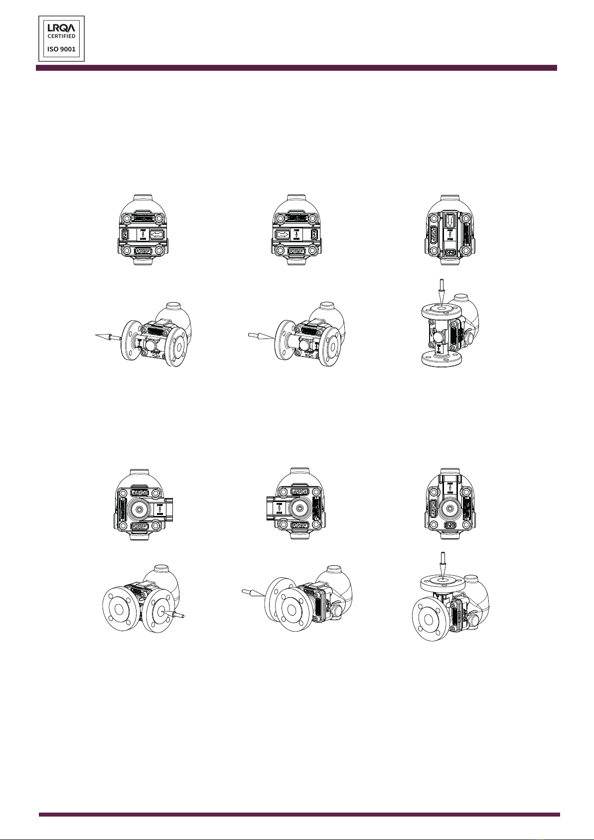
The following ow directions are possible for steam traps with inline connections:
Fig. 2 - Flow direction options for steam traps with inline connections.
IR - Horizontal from right to left IL - Horizontal from left to right IT - Vertical from top to bottom
The following ow directions are possible for steam traps with angled connections:
Fig. 3 - Flow direction options for steam traps with angled connections.
AR - Angled from right to front AL - Angled from left to front AT - Angled from top to front
VA L STEAM
ADCA
IMI FLT20.015 E 00.22
ADCA
16
To change ow direction proceed according to the following steps:
Fig. 4 - Flow direction change.
9 8
64
7
53110
24A
1. Undo the bolts (10) gradually in a crisscross pattern and separate the cover (2)
from the body (1).
2. Remove the body gasket (3) and clean surfaces thoroughly, leaving no remaining
graphite leftovers.
3. Unscrew the seat nut (4A), inspect the gasket (5) and replace if necessary.
4. Screw the seat nut (4A) loosely once again.
5. Rotate the body (1) to meet the desired ow direction according to Fig. 2 and Fig.
3, keeping the mechanism assembly (4, 6, 7, 8, 9) with the automatic air vent (9)
pointing upwards. Replace the "POINT DOWN" sticker accordingly.
6. Secure the seat (4) and tighten the seat nut (4A) with the recommended torque –
see section 9.6 – Tightening torques.
7. Fit a new body gasket (3) and install the cover (2) with the protruding section
pointing upwards.
8. Apply a suitable lubricant to the threads of the bolts (10), and tighten gradually in
a crisscross pattern until the recommended torque is acheived – see section 9.6 –
Tightening torques.

VA L STEAM
ADCA
IMI FLT20.015 E 00.22
ADCA
17
4.3. Installation procedure
1. Remove plastic lm and other packaging, as well as the protective covers which
are placed on anges or connection ends. Make sure the steam trap is free from
foreign matter.
2. The steam trap can be installed in any of the positions shown in Fig. 2 and Fig. 3.
3. The steam trap has an arrow or inlet/outlet designations, be sure that it is installed
in the appropriate direction according to uid ow. The "POINT DOWN" sticker
must have the arrow pointing downwards.
4. Take care with jointing materials and sealing compounds to ensure that none may
be permitted to block or enter the steam trap causing malfunction. In case of anged
connections use appropriate ange gaskets.
5. When a socket weld or butt weld version is being installed, the welding should
be carried out by qualifed personnel following an appropriate welding procedure.
Do not weld on top of the corrosion protection (paint, surface coatings). If there is
corrosion protection on the welding ends remove it before welding. After welding
the steam trap to the pipeline repair its corrosion protection.
6. When welding the steam trap to the pipeline make sure to restrict the heat-aected
area to the weld seam, if not possible remove the mechanism assembly (4, 6, 7, 8,
9) prior to welding – see section 9.2 – Cleaning/replacing the mechanism.
5. START-UP
Before performing the start-up procedure, refer to section 1 – Safety information.
The start-up procedure must be followed every time the product is put back into service.
5.1. Preparation for start-up
Before starting up, make sure the following conditions are met:
• All works on the system have been completed.
• All the necessary safety devices have been installed.
• When required, warning notices are used to alert others that the system is starting
up.
• The product is correctly installed – see section 4 – Installation.
• Referring to these Installation and Maintenance Instructions (IMI), Information Sheet
(IS) and nameplate, check that the product is suitable for the intended installation:
temperature, medium, pressure, temperature, etc. – see section 1.2 – Intended
use.
• A safety check was performed by qualied personnel. Checking for leaks, structural
damage and integrity of system components.

VA L STEAM
ADCA
IMI FLT20.015 E 00.22
ADCA
18
RISK OF PRODUCT DAMAGE DUE TO CONTAMINATION
The plant operator is responsible for cleaning the pipelines in the plant as
well as keeping the product well maintained. At start-up, the presence of
small particles in the medium (dirt, scale, weld splatters, etc.) may damage
the product or cause malfunction.
• Flush pipelines before start-up.
• Clean protection varnishes from pipes and anges, leftover paint, graphite,
grease, etc.
• Use a pipeline strainer or a lter.
NOTICE
5.2. Start-up procedure
1. Open shut-o valves slowly, until normal operating conditions are achieved.
2. Check for any leaks.
3. Check the steam trap to ensure it is operating correctly.
24 hours after system start-up, it is recommended to check pipe connection
for leaks and retighten when necessary. Clean strainers/lters to avoid
blocking.
NOTE

VA L STEAM
ADCA
IMI FLT20.015 E 00.22
ADCA
19
6. OPERATION
Before operating the product refer to section 1 – Safety information.
Immediately after completing the start-up procedure, the product is ready for operation.
6.1. Operating the BDV and HVV units
RISK OF BURNS FROM BDV AND HVV VALVE OPERATION
Operating the BDV and HVV valve discharges hot medium to the atmosphere
which may cause burn injuries.
• Wear protective clothing, safety glasses and heat-resistant gloves during
operation.
• When operating the valve stand to the side well clear of its outlet.
RISK OF INJURY DUE TO EXCESSIVELY LOOSENING THE BDV OR
HVV VALVE SCREW
Excessively loosening the valve screw while operating may cause the retainer
to break or come loose. This may result in the screw blowing o leading to
personal injury and product malfunction.
• Loosen the valve screw slowly and do not unscrew it excessively.
WARNING
1. Open the BDV or HVV by slowly unscrewing the valve screw. Be careful to avoid
contact with the hot medium which will be discharged trough the valve whole as it
opens.
2. Close the valve by tightening the valve screw to a torque of 20 to 25 Nm ensuring
that there is no leakage.
3. Periodical valve operation is recommended to ensure correct functioning.
6.2. Operating the FLL
1. Turn the lever (33) anticlockwise (viewing the lever from the front) to lift the oat
and open the valve seat.
2. Turn the lever (33) clockwise (viewing the lever from the front) to let the oat
drop and close the valve seat. If there is condensate inside the steam trap body
keeping the oat buoyant then the valve will only close once it has been discharged
independently if the lever (33) is turned clockwise or not.

VA L STEAM
ADCA
IMI FLT20.015 E 00.22
ADCA
20
7. SHUTDOWN
Before performing the shutdown procedure, refer to section 1 – Safety information.
7.1. Shutdown procedure
1. Switch o the system and secure it so it cannot be turned on by unauthorized
personnel.
2. Fully close the upstream shut-o valve, to stop the process medium from owing
through the steam trap.
3. Make sure the pipeline and the steam trap are not under pressure and are at a safe
temperature.
4. Allow medium to cool down and completely drain it from the pipeline and steam
trap.
5. Fully close the downstream shut-o valve.
6. If the steam trap is to be removed from the pipeline – see section 3 - Transport,
storage and packaging.
Other manuals for FLT
1
This manual suits for next models
9
Table of contents
Other ADCA Industrial Equipment manuals


