ADCA FLT16 Series User manual

ADCA
VALSTEAM
ADCA
We reserve the right to change the design and material of this product without notice.
IMI 1.332 E 04.14
INSTALLATION AND MAINTENANCE INSTRUCTIONS
FLOAT & THERMOSTATIC STEAM TRAPS
FLT16
GENERAL
These instructions must be carefully read before any work involving products supplied by VALSTEAM ADCA
ENGINEERING S.A. is undertaken.
The installation procedure is a critical stage in a life of a float trap and care should be taken to avoid damage to
the float trap or equipment.
Warning!
- At start up, the presence of small particles in the water (dirt, scale, weld splatters, etc) may cause an unperfected
closure of the seat. If this occurs, proceed to an accurate cleaning.
- Do not touch the equipment without appropriate protection during working operation because it may conduct heat
if the used fluid is at high temperature.
- Before starting maintenance be sure that the equipment is not pressurized or hot.
- The equipments must be used within the working temperature and pressure limits laid down for them, otherwise
they may fail (refer to nameplate and/or IS- Information Sheet).
- Do not remove the nameplate attached to the equipment. Serial number and other useful information is stamped
on it.
INSTALLATION
- Before to install remove plastic covers placed on flanges or connection ends. The equipment has an arrow or
Inlet/Outlet designations. Be sure that it will be installed on the appropriate direction.
- Install the steam trap in the point of the system, where the condensate tends to collect.
It must be installed with the float lever in horizontal plane, so that it rises and falls vertically.
An ADCA strainer should be installed upstream of the trap.
PMA: Max. allowable pressure 16 bar FLT 16-4,5 4,5 bar
TMA: Max. allowable temperature 250 ºC FLT 16-10 10 bar
PMO: Max. operating pressure 14 bar FLT 16-14 14 bar
TMO: Max. operating temperature 198 ºC
LIMITING CONDITIONS
MAX. DIFFERENTIAL PRESSURE
Installation area requirements:
The installation area should have easy access and provide enough space for maintenance and removing
operations.
The installation area should have the necessary firing system to prevent damage of the equipment due to over
temperature/pressure cause by fire.
ADCA
VALSTEAM
ADCA
We reserve the right to change the design and material of this product without notice.
IMI 1.332 E 04.14
MAINTENANCE
We recommend that the float steam traps are serviced as necessary. Steam traps should be checked
periodically (at least yearly), to verify that they are operating correctly and to clean the internal parts and screen
(if any).
When reassembling make sure that all gasket faces are clean and always use a new gasket. Tighten cover
bolts uniformly in a diagonal sequence.
For further information refer to the relevant FLT16 brochure or consult our Sales Office.
TROUBLESHOOTING
- If the malfunctions cannot be solved with the help of the following chart, please consult the manufacturer.
- Some of these faults may only occur in some models.
TROUBLE SHOOTING CHART
FAULT
POSSIBLE REASON
SOLUTION
Continuous steam discharge
Damaged seat.
Incorrect installation.
Substitute seat.
check the installation position
(see IMI 1.344 E 08.03).
The condensate isn’t discharged
Or not enough discharged
Obstructed strainer.
Inadequate pressure differential.
Excessive back pressure.
Damaged float.
Proceed to an accurate clean and
identify the possible reason of
contamination.
Check the steam trap D.P. and
substitute.
Replace the steam trap by a
superior DN or use ADCAMAT.
Replace.
Temporary condensate
accumulation
Steam blocking.
Downsizing.
Use a steam trap with SLR.
Check maximum flow rate (during
start-up)
Slow initial start up
Damaged air eliminator.
The air flow is too high for the trap.
Downsizing.
Replace.
Install an additional air eliminator.
Check maximum flow rate (during
start-up)

ADCA
VALSTEAM
ADCA
We reserve the right to change the design and material of this product without notice.
IMI 1.332 E 04.14
CE Marking:
This product has been designed for use on water and steam which are in
Group 2 of the European Pressure Equipment Directive 97/23/EC and it
comply with those requirements.
The product carries the CE mark when falling in category 1 and above.
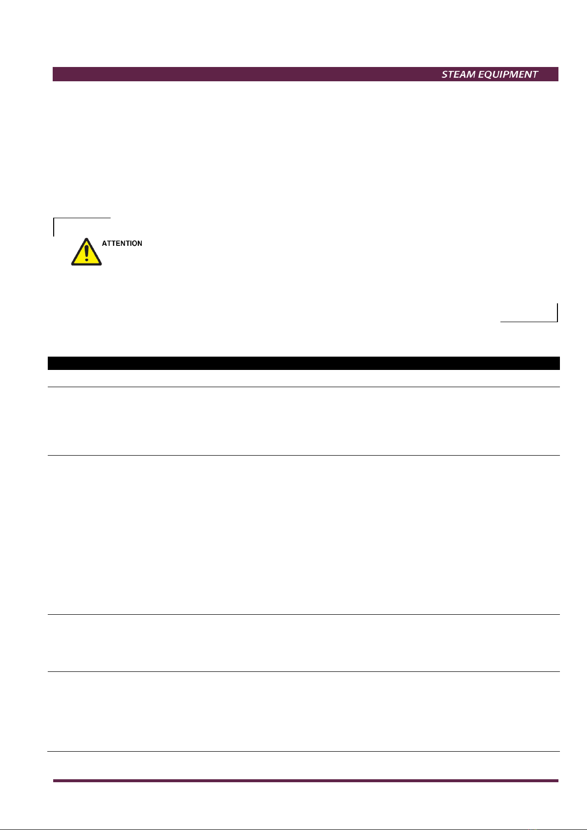
PARTS LIST FOR FLT16 DN ½’’ – ¾’’, DN 15 – 20:
TRAP SIZE
DN
A.92.1402.015 Valve, seat, float & gasket D.P. 4,5 bar 1/2'' - 3/4'' 3, 4, 5, 6, 7 1 set
A.92.1403.015 Valve, seat, float & gasket D.P. 10 bar 1/2'' - 3/4'' 3, 4, 5, 6, 7 1 set
A.92.1404.015 Valve, seat, float & gasket D.P. 14 bar 1/2'' - 3/4'' 3, 4, 5, 6, 7 1 set
A.92.1402.115 Float & gasket 1/2'' - 3/4'' 3, 7 1 set
A.92.1402.215 Air vent & gasket 1/2'' - 3/4'' 3, 8 1 set
CODE
DESIGNATION
QTY.
POS.NR.
Recommended tightening torques FLT16 DN ½’’ – ¾’’, DN 15 – 20:
TRAP SIZE
DN
4 1/2'' - 3/4'' 50-55
8 1/2'' - 3/4'' 50-55
9 1/2'' - 3/4'' 40-45
Remarks: Tighten cover bolts uniformly.
POS.NR.
Nm
PARTS LIST FOR FLT16 DN 1’’, DN 25:
TRAP SIZE
DN
A.92.1402.025 Valve, seat, float & gasket D.P. 4,5 bar 1'' 3, 4, 5, 6, 7 1 set
A.92.1403.025 Valve, seat, float & gasket D.P. 10 bar 1'' 3, 4, 5, 6, 7 1 set
A.92.1404.025 Valve, seat, float & gasket D.P. 14 bar 1'' 3, 4, 5, 6, 7 1 set
A.92.1402.125 Float & gasket 1'' 3, 7 1 set
A.92.1402.215 Air vent & gasket 1'' 3, 8 1 set
CODE
DESIGNATION
QTY.
POS.NR.
Recommended tightening torques FLT16 DN 1’’, DN 25:
TRAP SIZE
DN
4 1'' 50-55
8 1'' 50-55
9 1'' 40-45
Remarks: Tighten cover bolts uniformly.
POS.NR.
Nm
MODEL SIZES CATEGORY
FLT 16 DN 15-40 SEP
FLT 16 DN 50 1
GROUP 2 GASES CATEGORY
ADCA
VALSTEAM
ADCA
We reserve the right to change the design and material of this product without notice.
IMI 1.332 E 04.14
3
9 8
4
567
2
1
PARTS LIST FOR FLT16 DN 11/2’’ - 2’’, DN 40 - 50:
TRAP SIZE
DN
A.92.1402.040 Valve, seat, float & gasket D.P. 4,5 bar 11/2'' 3, 4, 5, 6, 7 1 set
A.92.1403.040 Valve, seat, float & gasket D.P. 10 bar 11/2'' 3, 4, 5, 6, 7 1 set
A.92.1404.040 Valve, seat, float & gasket D.P. 14 bar 11/2'' 3, 4, 5, 6, 7 1 set
A.92.1402.140 Float & gasket 11/2'' 3, 7 1 set
A.92.1402.050 Valve, seat, float & gasket D.P. 4,5 bar 2'' 3, 4, 5, 6, 7 1 set
A.92.1403.050 Valve, seat, float & gasket D.P. 10 bar 2'' 3, 4, 5, 6, 7 1 set
A.92.1404.050 Valve, seat, float & gasket D.P. 14 bar 2'' 3, 4, 5, 6, 7 1 set
A.92.1402.150 Float & gasket 2'' 3, 7 1 set
A.92.1402.215 Air vent & gasket 11/2''-2'' 3, 8 1 set
CODE
DESIGNATION
QTY.
POS.NR.
Recommended tightening torques FLT16 DN 11/2’’ - 2’’, DN 40 - 50:
TRAP SIZE
DN
4 11/2'' 10-15 (4xM6)
4 2'' 20-25 (4xM8)
8 11/2'' - 2'' 50-55
9 11/2'' 60-65
9 2'' 80-85
Remarks: Tighten cover bolts uniformly.
POS.NR.
Nm
ADCA
VALSTEAM
ADCA
We reserve the right to change the design and material of this product without notice.
IMI 1.332 E 04.14
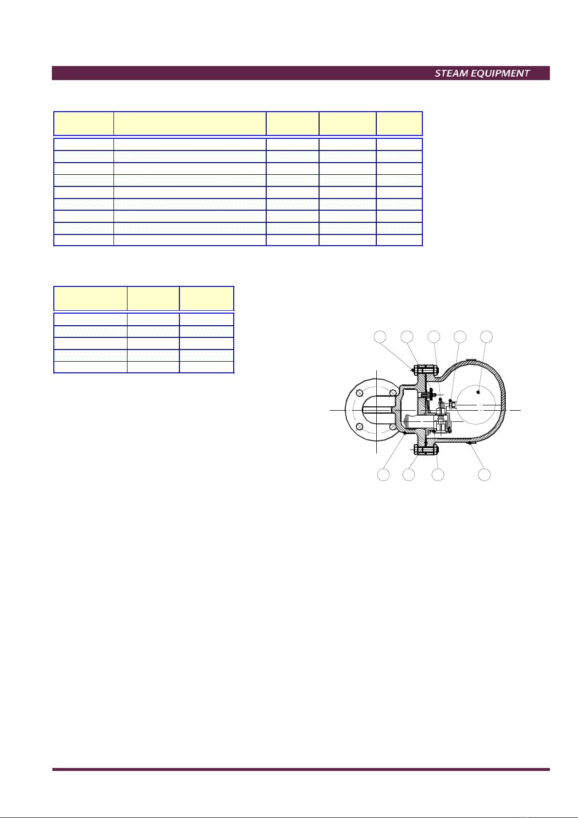
Correct Installation Wrong Installation
PRODUCTS RETURNING
- Information regarding any hazards and precautions to be considered because of contaminating fluids and
residues or mechanical damage that may represent a health, safety or environmental risk, must be provided in
writing by the distributors and costumers when returning products to Valsteam ADCA engineering.
- Health and safety data sheets regarding substances identified as hazardous or potentially hazardous must be
provided with the information mention above.
- LOSS OF WARRANTY: Total or partial disregard of above instructions involves loss of any right to warranty.
This manual suits for next models
3
Table of contents
Other ADCA Industrial Equipment manuals


