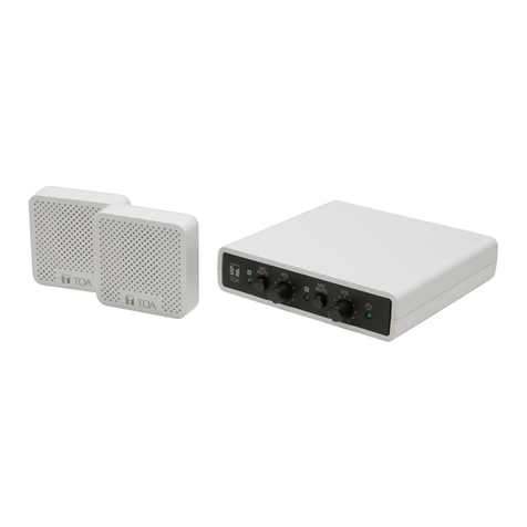
AddSecure Edge VS5010 User manual

PDK-15088-v.2.0 Connect Intercom User Manual.docx
Connect
Intercom
User manual

page 2 PDK-15088-v.2.0 Connect Intercom User Manual.docx
Table of Contents
1 About this manual...................................................................................3
2 Target group............................................................................................3
3 Introduction ............................................................................................3
3.1 Presentation of Connect Intercom..................................................3
3.2 Presentation of Addsecure connect ................................................3
4 Before you start ......................................................................................3
5 Board (PCBA) configuration ....................................................................4
6 Installing the terminal.............................................................................5
6.1 Mounting the terminal....................................................................5
6.2 Connecting power ...........................................................................5
6.3 Connecting backup batteries...........................................................5
6.4 Connecting the terminal..................................................................5
6.5 Powering up the terminal................................................................5
7 Activating the terminal ...........................................................................5
8 Configuring the terminal.........................................................................6
9 Commissioning........................................................................................6
9.1 Communication test........................................................................7
10 Maintenance routine ..............................................................................7
10.1 Periodic check of communications..................................................7
10.2 Maintaining data .............................................................................7
10.3 Confirm current status ....................................................................7
10.4 Periodic battery check: For the VS5051 ..........................................7
11 Specifications ..........................................................................................8
12 Safety ......................................................................................................9
13 Conformance...........................................................................................9
14 Contact..................................................................................................10
14.1
Installation and service support
.......................................................10
14.2 Sales enquiries...............................................................................10
15
Disclaimer
..............................................................................................10
16
Copyright
...............................................................................................10

PDK-15088-v.2.0 Connect Intercom User Manual.docx
page 3
1About this manual
This manual provides a guide to the installation and maintenance of the
Connect Intercom terminal. For local languages and full engineering manual,,
please visit our website.
2Target group
This manual is intended to provide assistance to engineers installing and
maintaining the Connect Intercom terminal at customer sites.
3Introduction
3.1 Presentation of Connect Intercom
Connect Intercom is a managed service solution for your door intercom
system. It uses either an Edge VS5051 terminal or an Edge VS5010 terminal
installed adjacent to and connected to a new or existing door intercom. It
provides a replacement IP telephony service using Session Initiation
Protocol (SIP) for existing telephony that uses PSTN or ATA technology.
PSTN telephony services have no monitoring capability. However, Connect
Intercom provides the possibility for the customer to monitor performance
themselves using the AddSecure AddView application.
Connect Intercom is easy to install and no additional configuration of the
system is required after activation because it is setup through AddSecure
Connect.
3.2 Presentation of Addsecure connect
AddSecure Connect is a cloud-based platform from AddSecure that manages
secure and controlled transmissions, for example, alarms, for Fire, Intruder,
Elevator, Technical and other alarms. The platform simplifies setting up
terminals and complying with regulations for the installer, the customer and
alarm receiving centres, (ARCs). AddSecure Connect is perfect for every
situation where monitored communication is desired, as well as when there is
a need for controlled remote access to external devices.
AddSecure Connect also includes the AddView web portal which allows both
customers and installers to monitor different installations and for setting up
notification services.
Addsecure can remotely analyse and setup an installati over AddSecure
Connect if required. You can read more about AddSecure Connect on
www.addsecure.com.
4Before you start
Ensure that a subscription to AddSecure Connect exists for this terminal before
starting the installation. If you or the customer do not already have one, please
contact AddSecure.

page 4 PDK-15088-v.2.0 Connect Intercom User Manual.docx
5Board (PCBA) configuration
①
Ethernet 1
⑨
Power out: Vout3 (Call Connect)
②
Ethernet 2
⑩
Power out: Vout2 (Buzzer)
③
LEDs
⑪
Power out: Vout1 (Emergency Light)
BT = Not in use
⑫
DC power in
PNL = Panel LED
⑬
Expansion port
PWR = Power LED
⑭
TTL serial port
CEL = Cellular LED
⑮
Pin inputs (4)
ETH = Ethernet LED
⑯
RS232 port
SYS = System LED
⑰
Case Tamper input
④
Cellular diversity antenna port (RX only)
⑱
PSU sense
⑤
SIM card slot
⑲
Outputs (3)
⑥
Primary cellular antenna port (TX/RX)
⑳
RS485 port
⑦
Test Button (Signal Strength)
Dial Capture port
⑧
USB port (diagnostics)
Battery port

PDK-15088-v.2.0 Connect Intercom User Manual.docx
page 5
6Installing the terminal
6.1 Mounting the terminal
The Edge VS5010 is not supplied with an enclosure, so the PCBA must first
of all be installed in a suitable enclosure.
The Edge VS5051 comes pre-installed in an enclosure.
The enclosure containing the terminal should be positioned close to the
intercom box and where there is a good cellular connection.
6.2 Connecting power
Power to the terminal must be provided from a power supply providing
10.5 to 28V DC with a recommended 2A current. The power supply must be
able to be connected to the terminal PCBA using the screw terminals.
The terminal can be powered from RCO intercom panels.
Addsecure can supply a suitable power supply as an accessory if required,
contact AddSecure for details.
IMPORTANT: You can connect the power supply but DO NOT APPLY
POWER TO THE TERMINAL NOW. This you will do later.
6.3 Connecting backup batteries
Connect the internal battery to the PCBA battery connector, see item 22 in
chapter 5, “Board Configuration”.
Note: Only use battery packs provided by AddSecure.
6.4 Connecting the terminal
Connect the cables from the intercom to the Dial Capture ports, see item 21
in chapter 5 “Board Configuration”.
6.5 Powering up the terminal
The terminal is now installed, so the power supply can now be connected.
Switch the power on and check that the indicator “SYS LED” is flashing (top
green LED on PCBA). If it does not, you need to contact AddSecure.
7Activating the terminal
The terminal can only be activated by using the Activator Service app Follow
this procedure to download the Activator Service app and activate the
terminal:

page 6 PDK-15088-v.2.0 Connect Intercom User Manual.docx
Step Action
1 Scan one of these QR-codes depending on your mobile device’s
operating system:
App Store QR code Google Play QR code
2 Download and install the AddSecure Service Activator.
3 Sign in or register an account. You will receive an email with an
auto-generated password.
4 Log in, and select “AddSecure Connect”.
5 Scan the QR-code that is on the label on the terminal enclosure.
6 Click “Activate”.
7 When “Configuring” is displayed, connect power to the terminal.
8 Finish this procedure by waiting approx. 3 minutes for the process
to finish.
When complete, “Service activated” will be displayed.
8Configuring the terminal
The terminal does not need to be configured. All the configuration is done
by AddSecure directly to the unit.
9Commissioning
VS5051 terminals do not require manual programming. All required
information for configuration will have been provided when the AddSecure
Subscription Application 5t was completed.
The terminal is delivered with relevant area code digits appended, e.g.
“0046” for deliveries to Sweden. If you need to change these appended
digits, contact AddSecure.
For the VS5051 terminal: You can check the status of the LEDs on the lid of
the terminal enclosure to ensure settings have been correctly downloaded.
If LEDs do not have these states after successfully using the Activator
Service app, please contact your local AddSecure Support team for
Purpose
Single Path “Status OK”
Panel (PNL)
ON = OK
Power (PWR)
ON = OK
Short blip = charging
Flicker = battery problem
Cellular Path (CEL)
ON = OK
Short blips = sending data
Ethernet Path (ETH)
Not Enabled
System (SYS)
ON = OK

PDK-15088-v.2.0 Connect Intercom User Manual.docx
page 7
assistance. If all the LEDs are correct, a simple communication test should
be run, see section 9.1 below.
9.1 Communication test
To perform a simple communication test, one of the intercom buttons must
be set to call your mobile phone.
Start the test by pressing the reprogrammed intercom button. Your mobile
phone should ring and display the intercom screen. Respond by clicking
«Open the door». If the door lock unlocks, this indicates that there is clear
two-way communication.
After the test, the intercom button must be reprogrammed back to the
correct telephone number.
10 Maintenance routine
Maintenance routines are as follows:
Periodic check of communications.
Maintaining data.
Confirm current status.
Periodic battery check (VS5051 only).
10.1 Periodic check of communications
This is simply to ensure that the terminal is still online. Check that the
Cellular LED, marked “CEL” (3 in section 5 “Board configuration”) is lit. If it
is, cellular connection is good. If it is not lit, troubleshoot your cellular
signal.
10.2 Maintaining data
To change phone numbers, refer to the manual for the intercom panel.
AddSecure maintains information about account numbers and information,
based on input from the owner or service partner. To make changes to this,
contact AddSecure.
10.3 Confirm current status
Check the status by checking the LEDs on the lid of the unit.
When a LED is lit, that indicates that this particular function is working
correctly. For details, see section 9 “Commissioning”.
10.4 Periodic battery check: For the VS5051
The status of the battery should be manually checked periodically even
though the battery status is continuously tested automatically. If the self-
test finds the battery faulty, the Power LED will flicker, (see section 9
“Commissoning”) and a message will be sent through AddSecure Connect
to the ARC. The battery should then be replaced with a new battery from
AddSecure.

page 8 PDK-15088-v.2.0 Connect Intercom User Manual.docx
11 Specifications
Section
Details
Ethernet
Standard
10/100 Base T with auto-negotiation, up to 100m
Connection
RJ45 socket for CAT5 cabling
IP addressing
Dynamic (DHCP) or fixed
Fault detection
Loss of Ethernet synchronisation
Wi-Fi
Standard
IEEE 802.11 b/g/n
Connection
2.4GHz b/g/n with internal PCBA chip antenna
Fault detection
Loss of association/data
4G/3G/2G
Frequencies
Penta band LTE (4G)
800/900/1800 MHz
2100/2600 MHz
Dual band UMTS (3G)
900/2100 MHz
Dual band GSM (2G)
900/1800 MHz
Connection
MMCX socket for antenna, 2nd RX antenna socket for diversity
Fault detection
Loss of registration with network
IP
TCP ports (outbound)
53165 (Alarms & Polling), 51292 (Diagnostic & Reflashing),
10001 (Upload/Download)
Alarm transmission interfaces
Interface to ARC
AddSecure Connect
Dial capture interface to voice
panel
Two-wire interface via terminal block.
Serial interfaces
RS485, TTL (max 3 metres), RS232 (max 3 metres)
PIN Inputs interface
Maximum input voltage range 0V to +28V DC (max 3 metres)
Input “low” (alarm) threshold < 1V
Input “high” (restore) threshold > 2V
Internal pull-up impedance 10K to 3.3V supply
Relay outputs
Maximum operating voltage
24V DC
Maximum current rating
100mA DC
Local configuration
Bluetooth
Dual mode Bluetooth 4.0
USB
Micro USB device, for use with IRIS Toolbox
Power supply
Supply voltage
10.5V to 28V DC
Typical current (no DC outputs)
200mA @12V DC (not charging), 500mA @12V DC (charging)
Maximum current (no DC outputs)
1A @12V DC
Recommended external PSU (with
DC power outputs)
15V DC 2A 30 Watt.
Note: To comply with the Radio Equipment Directive,
2014/53/EU.
DC power outputs

PDK-15088-v.2.0 Connect Intercom User Manual.docx
page 9
Section
Details
Output voltage
12V DC
Total output current (shared,
continuous rating)
500mA
Current protection
1.5A electronic protection, 2.2A polyfuse
Number of switchable outputs
3
Voltage at which fault is reported
10V
Voltage at which fault is restored
11V
Power storage device
Type
7.2V NiMH rechargeable batteries
Capacity
3000mAh
Time to recharge to 80% capacity
16 hours
Voltage at which fault is reported
6.75V DC
Voltage at which fault is restored
7.50V DC
Over-voltage protection triggered
9.5V DC
Deep discharge protection
6V DC
Environmental
Operating temperature range
-10°C to 55°C
Operating humidity range
95% max., non-condensing
Weights and dimensions
Physical dimensions (L x W x D)
15 cm x 17 cm x 5.1 cm
Terminal weight (housing, PCBA,
battery)
1.2 Kg
Fully packaged weight
1.8 Kg
12 Safety
In order to avoid safety hazards, care should be taken when connecting
telecommunications equipment to ensure that only compatible interfaces
are connected. This is measured using SELV values. These are defined as a
secondary circuit which is so designed and protected that under normal and
single fault conditions, the voltage between any two accessible parts does
not exceed a safe value (42.4V AC peak or 60V DC maximum).
The terminal's interfaces have the following safety classifications:
Dial capture interface: SELV suitable for connections to the Telephone Network
Voltage (TNV) interface of single line telecommunications equipment such as
telephones, alarm panels, etc.
Power Interface: SELV for connection to DC Supply
Inputs: SELV for connection to alarm output pin.
13 Conformance
The terminal complies with the following European Directives and
standards:
2014/53/EU (Radio Equipment Directive)
2002/96/EC (WEEE)
2011/65/EC (ROHS)
No. 1907/2006 (REACH)

page 10 PDK-15088-v.2.0 Connect Intercom User Manual.docx
14 Contact
General: www.addsecure.com
14.1
Installation and service support
Norway
Sweden
Telephone: +47 911 33 700
Telephone:
+46 20 322 000
Email:
support.smartalarms.no@addsecur
e.com
Email
:
support.smartalarms.no@addsecur
e.com
14.2 Sales enquiries
Norway
Sweden
Tel. no.: +47 911 33 700
Tel. no.:
+46 8 685 15 10
Emain address:
order.smartalarms.no@addsecure.
com
Emain address:
order.smartalarms.no@addsecure.
com
15
Disclaimer
The information contained in this document is supplied without liability for any
errors or omissions.
16
Copyright
No part of this document may be reproduced or used except as authorised by
contract or other written permission from AddSecure. The copyright and
foregoing
restriction on reproduction and use extend to all media in which
the information may be embedded.
© 2019 AddSecure
Other manuals for Edge VS5010
1
This manual suits for next models
1
Table of contents
