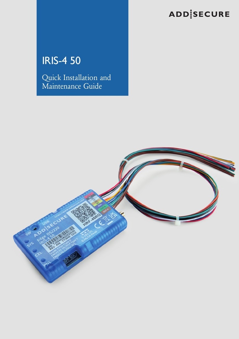
AddSecure IRIS-4 Product manual

IRIS-4 Technical Reference Manual.docx 12/01/2023
IRIS-4
Terminals
Technical Reference
Manual

page 2 IRIS-4 Technical Reference Manual.docx 12/01/2023
Table of Contents
1 About this manual ................................................................................................................ 7
1.1 Target group ................................................................................................................................. 7
1.2 Scope ............................................................................................................................................. 7
2 About the IRIS-4 product range ........................................................................................... 8
3 Circuit board layouts ............................................................................................................ 9
3.1 The 160 ......................................................................................................................................... 9
Sys LED indications ........................................................................................................................ 9
3.2 The 2xx ........................................................................................................................................ 10
Sys LED indications ...................................................................................................................... 10
3.3 The 4xx ........................................................................................................................................ 11
Sys LED indications ...................................................................................................................... 11
Expansion boards ........................................................................................................................ 11
3.4 The 6xx ....................................................................................................................................... 12
LED indications ............................................................................................................................ 12
4 Basic setup ......................................................................................................................... 13
4.1 Before you begin ........................................................................................................................ 13
ARC ............................................................................................................................................... 13
Ethernet connection details ....................................................................................................... 13
Cellular SIM card and Access Point Name ................................................................................. 13
4.2 Recommended installation sequence ....................................................................................... 14
Installing the Extension boards on the 4xx ................................................................................ 14
4.2.1.1
Expansion boards .................................................................................................... 15
Mount the terminal .................................................................................................................... 15
4.2.2.1
Mounting the 160 ................................................................................................... 15
4.2.2.2
Mounting the 2xx .................................................................................................... 15
4.2.2.3
Mounting the 4xx & 6xx .......................................................................................... 16
Position the antenna ................................................................................................................... 16
Connect cables ............................................................................................................................ 16
4.2.4.1
Cables ....................................................................................................................... 16
4.2.4.2
Serial connections ................................................................................................... 16
4.2.4.3
Power Supply ........................................................................................................... 17
Power up ..................................................................................................................................... 17
4.2.5.1
Using the terminal touchscreen ............................................................................. 17
4.2.5.2
Using the virtual touchscreen ................................................................................. 17
Welcome menus ......................................................................................................................... 18
4.2.6.1
Language selection .................................................................................................. 18
4.2.6.2
Installer’s password ................................................................................................. 18
5 Configuring the terminal .................................................................................................... 19
5.1 Accessing the Installation Wizard .............................................................................................. 19
5.2 Initial configuration settings ...................................................................................................... 19
Select interfaces .......................................................................................................................... 19
Battery backup ............................................................................................................................ 19
Additional options ....................................................................................................................... 19
Account name/number .............................................................................................................. 20
ARC IP address ............................................................................................................................. 20
5.3 Communication configuration ................................................................................................... 20
Communication tests .................................................................................................................. 21
5.3.1.1
Connection failed .................................................................................................... 21
5.3.1.2
Connection made, Poll failed .................................................................................. 21
5.3.1.3
Authentication failed ............................................................................................... 21
Checking S/W version ................................................................................................................. 21
Ethernet setup and test .............................................................................................................. 22

IRIS-4 Technical Reference Manual.docx 12/01/2023 page 3
5.3.3.1
Checking Ethernet connection ............................................................................... 22
5.3.3.2
Dialler IP Address..................................................................................................... 22
5.3.3.3
Ethernet communications tests ............................................................................. 22
Wi-Fi setup and test .................................................................................................................... 23
5.3.4.1
Wi-Fi settings ........................................................................................................... 23
5.3.4.2
Checking Wi-Fi connection ..................................................................................... 23
5.3.4.3
Wi-Fi communication tests ..................................................................................... 23
Cellular setup and test ................................................................................................................ 24
5.3.5.1
Cellular registration ................................................................................................. 24
5.3.5.2
Cellular signal strength............................................................................................ 24
5.3.5.3
Cellular settings ....................................................................................................... 24
5.3.5.4
Cellular communication tests ................................................................................. 25
PSTN Setup & test ....................................................................................................................... 25
5.3.6.1
PSTN connection test .............................................................................................. 25
5.4 Further configuration settings ................................................................................................... 25
Dial port check ............................................................................................................................ 25
Pin alarms .................................................................................................................................... 25
5.4.2.1
PSTN: Alarm Setup .................................................................................................. 25
5.4.2.2
Pin format ................................................................................................................ 25
5.4.2.3
Pins required............................................................................................................ 26
5.4.2.4
Monitor for tampers ............................................................................................... 26
Setup complete ........................................................................................................................... 26
5.5 Configuring the 160 using the Installer App: ............................................................................ 26
6 Settings .............................................................................................................................. 27
6.1 Network interfaces ..................................................................................................................... 27
6.2 Account name/number .............................................................................................................. 27
6.3 ARC IP address ............................................................................................................................ 27
6.4 Eth 1: For terminals with Ethernet capability ........................................................................... 27
6.5 Eth 2: For terminals with dual Ethernet capability ................................................................... 27
Cellular Bridge ............................................................................................................................. 28
6.5.1.1
DHCPSRV or Fixed.................................................................................................... 28
6.5.1.2
Cell/Client IP ............................................................................................................ 28
6.5.1.3
Subnet mask ............................................................................................................ 28
6.5.1.4
Gateway ................................................................................................................... 28
Cellular Routed ............................................................................................................................ 28
6.5.2.1
DHCPSRV or Fixed.................................................................................................... 28
6.5.2.2
Eth 2 IP/Gateway ..................................................................................................... 28
6.5.2.3
Subnet mask ............................................................................................................ 28
6.5.2.4
Cellular IP ................................................................................................................. 29
6.5.2.5
Forwarded IP ........................................................................................................... 29
6.6 Wi-Fi: For terminal with Wi-Fi capability .................................................................................. 29
Network ....................................................................................................................................... 29
Password ..................................................................................................................................... 29
Wi-Fi network scan ..................................................................................................................... 29
Wi-Fi signal strength ................................................................................................................... 29
IP address .................................................................................................................................... 29
6.7 Cellular Settings: For terminals with cellular capability ........................................................... 29
Signal strength............................................................................................................................. 29
Run network scan........................................................................................................................ 30
APN .............................................................................................................................................. 30
Username .................................................................................................................................... 30
Password ..................................................................................................................................... 30
SIM PIN ........................................................................................................................................ 30
Call barring .................................................................................................................................. 30

page 4 IRIS-4 Technical Reference Manual.docx 12/01/2023
SMS transport ............................................................................................................................. 30
Mode ........................................................................................................................................... 30
6.8 Battery backup: .......................................................................................................................... 31
6.9 Panel interface............................................................................................................................ 31
Dial port: ...................................................................................................................................... 32
6.9.1.1
Monitor cable .......................................................................................................... 32
6.9.1.2
Report polling fail .................................................................................................... 32
6.9.1.3
Enable Ringtone ...................................................................................................... 32
6.9.1.4
Voice call alarm ....................................................................................................... 32
6.9.1.5
Ring .......................................................................................................................... 32
6.9.1.6
Dial tone ................................................................................................................... 32
6.9.1.7
PSTN Only ................................................................................................................ 33
6.9.1.8
Telim conversion ..................................................................................................... 33
COM ............................................................................................................................................. 33
6.9.2.1
Monitor cable .......................................................................................................... 33
6.9.2.2
Report poll fail ......................................................................................................... 33
6.9.2.3
Emulation mode ...................................................................................................... 33
6.9.2.4
Serial settings........................................................................................................... 33
RS232 (1) ..................................................................................................................................... 33
6.9.3.1
Monitor cable .......................................................................................................... 33
6.9.3.2
Report poll fail ......................................................................................................... 33
6.9.3.3
Emulation mode ...................................................................................................... 33
6.9.3.4
Serial settings........................................................................................................... 34
RS232 (2) ..................................................................................................................................... 34
6.9.4.1
Monitor cable .......................................................................................................... 34
6.9.4.2
Report polling fail .................................................................................................... 34
6.9.4.3
Emulation mode: For 4xx and 6xx .......................................................................... 34
6.9.4.4
Serial settings........................................................................................................... 35
Serial port RS485 ......................................................................................................................... 35
6.9.5.1
Galaxy ....................................................................................................................... 35
6.9.5.2
ProSYS ...................................................................................................................... 35
6.9.5.3
ESMI ......................................................................................................................... 35
Eth 2 ............................................................................................................................................. 36
6.10 Alarm override ............................................................................................................................ 36
6.11 Extra features ............................................................................................................................. 36
Normal ......................................................................................................................................... 36
Set / unset ................................................................................................................................... 36
6.11.2.1
Set / unset pin ......................................................................................................... 36
6.11.2.2
Exit delay .................................................................................................................. 36
6.11.2.3
Entry Pin ................................................................................................................... 36
6.11.2.4
Entry delay ............................................................................................................... 37
6.11.2.5
Set status relay ........................................................................................................ 37
6.11.2.6
Alarm status relay.................................................................................................... 37
ENS4-21 Fire ................................................................................................................................ 37
VdS 2463 Intruder ....................................................................................................................... 37
VdS 2463 Fire .............................................................................................................................. 37
ILKA mode + PSU ......................................................................................................................... 37
ILKA mode .................................................................................................................................... 37
Tamper detection ....................................................................................................................... 37
INCERT 2+/3 ................................................................................................................................ 37
Test alarm .................................................................................................................................... 38
Add SIA Timestamp ..................................................................................................................... 38
6.12 Incoming IP address ................................................................................................................... 38
6.13 Pin inputs .................................................................................................................................... 38
Common options ......................................................................................................................... 38
6.13.1.1
Monitor cable .......................................................................................................... 38

IRIS-4 Technical Reference Manual.docx 12/01/2023 page 5
6.13.1.2
Enable ...................................................................................................................... 38
6.13.1.3
Inverse polarity ........................................................................................................ 38
Alarm format SMS ....................................................................................................................... 39
6.13.2.1
Phone number ......................................................................................................... 39
6.13.2.2
Set msg and Restore msg ........................................................................................ 39
Alarm format SIA ......................................................................................................................... 39
6.13.3.1
Set msg and Restore msg ........................................................................................ 39
Alarm format FF .......................................................................................................................... 40
6.13.4.1
Alarm ........................................................................................................................ 40
6.13.4.2
O/C (open/close) ..................................................................................................... 40
Alarm format CID ........................................................................................................................ 40
6.13.5.1
Event ........................................................................................................................ 40
6.13.5.2
Group ....................................................................................................................... 40
6.13.5.3
Zone ......................................................................................................................... 40
6.13.5.4
Default CID Set/Restore event codes ..................................................................... 41
6.14 Relays .......................................................................................................................................... 41
Relay input follower .................................................................................................................... 41
Relay SMS activation ................................................................................................................... 41
6.14.2.1
Phone number ......................................................................................................... 41
6.14.2.2
Activation msg ......................................................................................................... 42
6.14.2.3
Deactivation msg ..................................................................................................... 42
Relay invert .................................................................................................................................. 42
6.15 Trouble reporting ....................................................................................................................... 42
Via relays ..................................................................................................................................... 42
Via SMS ........................................................................................................................................ 43
Diagnostic call IP address............................................................................................................ 43
Diagnostic call.............................................................................................................................. 43
6.16 PSTN Settings .............................................................................................................................. 43
PSTN Alarm Setup ....................................................................................................................... 43
Audio ............................................................................................................................................ 43
Tone Detect ................................................................................................................................. 43
6.17 Language ..................................................................................................................................... 44
6.18 Installers password ..................................................................................................................... 44
6.19 Display ......................................................................................................................................... 44
Touchscreen calibration ............................................................................................................. 44
6.20 Default ........................................................................................................................................ 45
For terminals with an AP button (this is not part of Settings menu) ....................................... 45
6.21 Build information........................................................................................................................ 45
6.22 Reflash ........................................................................................................................................ 45
Reflash Access Password ............................................................................................................ 45
Reflash IP address ....................................................................................................................... 45
Reflash now ................................................................................................................................. 46
7 Installation for EN54-21:2006 compliance ......................................................................... 47
7.1 Introduction ................................................................................................................................ 47
7.2 General description of the equipment ...................................................................................... 47
Technical specification ................................................................................................................ 47
7.3 Installation, configuration, and commissioning ........................................................................ 47
Monitoring requirements ........................................................................................................... 47
Requirements for the installation .............................................................................................. 47
Configuration requirements ....................................................................................................... 48
8 Installation for VdS 2463 Compliance ................................................................................ 50
8.1 Introduction ................................................................................................................................ 50
8.2 Installation .................................................................................................................................. 50
8.3 VdS mode operation .................................................................................................................. 51

page 6 IRIS-4 Technical Reference Manual.docx 12/01/2023
8.4 VdS Intruder Applications .......................................................................................................... 51
8.5 VdS Fire Applications .................................................................................................................. 52
8.6 Conformance to VdS2463 .......................................................................................................... 53
9 Trouble reporting and test ................................................................................................. 54
9.1 Trouble report ............................................................................................................................ 54
9.2 Test .............................................................................................................................................. 55
Test .............................................................................................................................................. 55
Disable Cellular ............................................................................................................................ 56
10 Maintenance ...................................................................................................................... 57
10.1 Checking for faults ...................................................................................................................... 57
10.2 Checking battery status ............................................................................................................. 57
10.3 Upgrading software .................................................................................................................... 57
10.4 End to end tests.......................................................................................................................... 57
11 Technical specifications...................................................................................................... 58
12 Conformance ..................................................................................................................... 60
Appendix 1: Setting up the IRIS Toolbox .................................................................................... 61
Starting the IRIS Toolbox ....................................................................................................................... 61
Appendix 2: Abbreviations used by AddSecure ......................................................................... 62

IRIS-4 Technical Reference Manual.docx 12/01/2023 page 7
1 About this manual
This Technical Reference manual applies to the complete range of IRIS-4 models, see chapter 2 “About IRIS-4
product range”.
1.1 Target group
This document is intended as a technical reference for engineers and for anybody that needs technical
information about the IRIS-4 range of terminals.
1.2 Scope
This document has all the technical information about the iRIS-4 range of terminals running software version
4.15.0. Information about connecting to proprietary terminals is in the separate documents.
The manual has these chapters:
1 About this manual Describes the range and scope of the manual.
2 About the IRIS-4 product range Presents the terminals in the IRIS-4 range.
3 Circuit board layouts Presents the Printed Circuit Boards (PCB) for each terminal.
4 Basic Setup Explains how to install the terminals.
5 Configuring the terminal Explains how to configure the terminals for their purpose.
6 Settings Explains how to configure all the settings.
7 Installation for EN54-21:2006
Compliance
Installation instructions for complying with this standard.
8 Installation for VdS 2463
Compliance
Installation instructions for complying with this standard.
9 Trouble reporting and test Explains how the terminal reports problems and how to test an
installation.
10 Maintenance Explains maintenance procedures.
11 Technical Specifications Lists all the technical specifications for the products.
12 Conformance Lists the standards to which the products conform.
A1
Setting up the IRIS Toolbox Explains how to install the IRIS Toolbox.
A2
Abbreviations used Lists and explains all abbreviations used in the document.

page 8 IRIS-4 Technical Reference Manual.docx 12/01/2023
2 About the IRIS-4 product range
Below are the IRIS-4 models and their functions:
Touchscreen
Ethernet
Cellular (2/3/4G)
Dial capture
Wi-Fi
Pin inputs
Relays
Serial RS485
Serial TTL
Serial RS232
Enclosure
Bluetooth
Battery
160
4 3
1
200
4 3
1
220
4 3
1
240
4 3
1
240AP
4
4 3
1
400
4
1
4
2
2
420
2
4
1
4
2
2
440
2
4
1
4
2
2
440G
3
2
4
1
4
2
2
620
6 4
2
620D 2 6 4
2
640
6 4
2
640D 2
6 4
2
Notes:
1) The number of pin inputs on the 4xx can be extended by 12 using an Extension (EXT) board,
providing a total of 16 pin inputs.
2) The two basic serial RS232 ports on the 4xx can be converted to a single full port if required.
3) The 440G is virtually identical to the 440, except that:
Ethernet and Cellular will not work/power up, without external power being supplied.
They are disabled when only powered by USB and show a fault message on the
touchscreen accordingly. USB is for programming only.
Serial port RS232(2) no longer supports 1200 baud.
There is an AP button, like the 6xx series, so you can default the terminal on power up.
4)
The 240AP has only 3 & 4G with frequencies required for Asia Pacific.

IRIS-4 Technical Reference Manual.docx 12/01/2023 page 9
3 Circuit board layouts
3.1 The 160
Sys LED indications
LED
color
Light
Indication
Flashing Default state not currently configured.
Constant Successfully connected, but still outstanding faults. See
section 9.1, “Trouble report”.
Flashing Bluetooth mode, but no active connection.
Constant Bluetooth mode with an active connection.
Constant
Communicating, no current faults (flickers on every poll)
.
①= Release clip
②= Sense screw terminal
③= DC power screw terminals
④= Micro USB connector
⑤= Serial (TTL) connector
⑥= RS485 screw terminals
⑦= RS232 screw terminals
⑧= Relay outputs screw terminals
⑨= Dial capture port screw terminals
⑩= Pin input screw terminals
⑪= Bluetooth button
⑫= Ethernet connector
⑬= Battery case
⑭= SIM card holder
⑮= Cellular antenna
⑯= Sys LED

page 10 IRIS-4 Technical Reference Manual.docx 12/01/2023
3.2 The 2xx
Sys LED indications
LED Color Indication
Yellow
flashing Not configured or indicating there are current faults
outstanding. See section 9.1, “Trouble report”.
Yellow
constant Communicating and no current faults (flickers on every poll).
①
= Touchscreen
②= Serial (TTL) (not supported)
③= Case tamper switch
④= Dial capture port screw terminals
⑤= RS485 screw terminals
⑥= Pin input screw terminals
⑦= SIM card holder
⑧= Cellular antenna socket
⑨= Ethernet connector
⑩= DC power screw terminals
⑪= Relay outputs screw terminals
⑫= RS232 screw terminals
⑬= Micro USB connectors
⑭= Sys LED

IRIS-4 Technical Reference Manual.docx 12/01/2023 page 11
3.3 The 4xx
Sys LED indications
LED Color Indication
Yellow
flashing Not currently configured or indicating there are current
faults outstanding. See section 9.1, “Trouble report”.
Yellow
constant Communicating and no current faults (flickers on every poll).
Expansion boards
An expansion board can be added to the 4xx main board. There are 3 variants:
EXT1: provides additional 12 pin inputs.
EXT2: provides additional 12 pin inputs and a standard PSTN analog line interface (PSTN) as an outbound
transmission path for alarms.
EXT3: provides an additional 12 pin inputs and 3 mechanical relays (EXT3 not supported on 4xxG boards)
See section 4.2.1 “Installing the Extension boards on the 4xx” for installation instructions.
①
= 2 x RS232 screw terminals
②
= CAN bus (not supported)
③
= RS485 screw terminals
④
= Dial capture port, RJ45 &
screw terminals
⑤
= External tamper screw terminals
⑥
= DC power screw terminals
⑦
= Touchscreen
⑧
= SIM card holder
⑨
= Expansion board connector
⑩
= Cellular antenna socket
⑪
= Ethernet 1 connector
⑫
= Ethernet 2 connector
⑬
= Sys LED
⑭
= Serial (TTL) connector
⑮
= Micro USB connector
⑯
= Relay outputs screw terminals
⑰
= Pin input screw terminals
⑱
= 10-way headers for full RS232
connection
⑱

page 12 IRIS-4 Technical Reference Manual.docx 12/01/2023
3.4 The 6xx
LED indications
LED status Indication
SYS On Terminal is operational and all systems ok.
Flashing Not currently configured or indicating there are
current faults outstanding. See section 9.1,
“Trouble report”.
SIM On Terminal can see the SIM card (IRIS-4 640D).
Off Terminal cannot see the SIM card (IRIS-4 640D).
GSM On GSM connected / registered (IRIS-4 640D).
Off GSM Not connected / registered (IRIS-4 640D).
GPRS/3G On Terminal has network connection (IRIS-4 640D).
Off Terminal has no network connection (IRIS-4
640D).
Ethernet On ETH connected / synchronized.
Off ETH disconnected / not synchronized.
Serial Flashing
0.2s on/ off
Not communicating with panel.
Flashing
1.5s on/off
Terminal not configured.
Flashing
0.1s on/0.9s off
Normal communication.
Poll On (flickers per
poll)
Successfully polling with ARC.
Off Not polling with ARC.
①
= Cellular antenna socket
②
= Serial (TTL) connector
③
= RS485 connector and screw
terminals
④
= DC power screw terminals
⑤
= 2 x RS232 screw terminals
⑥
= Ethernet 1 connector
⑦
= Pin input screw terminals
⑧
= AP button
⑨
= Relays screw terminals
⑩
= SIM card holder
⑪
= LEDs
⑫
= Micro USB connector
⑬
= Ethernet 2 connector

IRIS-4 Technical Reference Manual.docx 12/01/2023 page 13
4 Basic setup
4.1 Before you begin
ARC
Make sure that the Alarm Receiving Center (ARC) to which the terminal will send alarm signals has the
appropriate IRIS Secure Apps (ISA) receiving system. The following information should be obtained from the
ARC.
Terminal account no:
ARC IP address:
Ethernet connection details
If the installation uses Ethernet, the customer’s Ethernet network (LAN) must be connected to the terminal.
Obtain the following information from the customer.
Will the terminal be required to use either:
Fixed IP address or Dynamic Host Configuration Protocol (DHCP)
Note: If using Fixed IP Address, then the following additional information will be required
.
IP address:
Gateway address:
Subnet mask:
Cellular SIM card and Access Point Name
If the installation uses cellular then a SIM card will be required. The terminal will also need to be given a
cellular Access point name (APN) and other possible configurations. Obtain the information from your SIM
card provider.
APN:
Username (USR):
Password (PWD):
SIM pin code:

page 14 IRIS-4 Technical Reference Manual.docx 12/01/2023
4.2 Recommended installation sequence
We recommend that you follow this installation sequence:
Add Extension board (if required)
Mount the terminal
Position the antenna
Connect cables to the terminal
Power up
Use Touchscreen menus
Note: that the term “touchscreen” as used in this document refers to both the physical touchscreen on a
terminal PCB and the virtual touchscreen provided in the IRIS Toolbox.
Installing the Extension boards on the 4xx
Expansion boards plug directly into the terminal with no additional wiring.
Use the following procedure to install your expansion board:
1 Power down the terminal.
2 Remove the PCB from its casing.
3 Align the expansion board over the expansion socket and mounting holes.
4 Slowly, but firmly, push down the module onto the PCB until the expansion pin header is fully inserted
into the EXP header.
5 Turn over the PCB and secure the two expansion pillars with the
screws and washers supplied.
6 Now turn the PCB over again and mount it back into the casing.
2-screw
terminal
block

IRIS-4 Technical Reference Manual.docx 12/01/2023 page 15
4.2.1.1 Expansion boards
An expansion board can be fitted to the main terminal to provide additional functionality.
4.2.1.1.1 Pin Inputs
The EXT1 expansion board provides 12 additional pin inputs
4.2.1.1.2 PSTN and input pins
The EXT2 expansion board provides 12 additional pin inputs and a PSTN Dial-out
for a PSTN connection via the 2-screw terminal block (see Figure 4).
Connect the PSTN line to the PSTN screw terminals, which are not polarity
sensitive.
4.2.1.1.3 Relays and input pins
The EXT3 expansion board provides 12 additional pin inputs and 3 mechanical relay outputs. This board is
not supported on the 4xxG.
Mount the terminal
4.2.2.1 Mounting the 160
Choose a suitable location, considering the routing of both power and terminal interface cables. Follow this
procedure:
1 Remove the cover by removing the two screws accessible through the cover.
2 Once released, lift the lid slightly and push until lid comes off.
3 Remove the terminal PCB (retained by two clips to left and right off the board).
4 Position the housing on the wall and drill three holes.
5 Feed the cables through the opening at the base of the plate, or via the ‘knock-outs’, and secure
the plate to the wall with the three screws supplied.
6 Slide the PCB back into the top retainers and within the side pillar and then gently secure the
terminal back in place using the release clips.
7 Continue with installation and configuration of the terminal.
8 When finished, re-attach the cover with the two screws. This also affixes the PCB in place.
4.2.2.2 Mounting the 2xx
Choose a suitable location, considering the routing of cables
for both power and
the
panel
terminal
interface. Remove the
two case fixing screws under the slide cover and open the unit.
Now release the two
clips on the base holding the PCB in place.
Position the housing on the wall and drill three holes. Feed the cables through the opening at the base of the
plate, or via the
'knock-outs’, and secure the plate to the wall with the three screws supplied.
Continue with installation and configuration of the terminal.
When finished, re-attach the cover with the two screws and re-position the slide cover.
Figure 4

page 16 IRIS-4 Technical Reference Manual.docx 12/01/2023
4.2.2.3 Mounting the 4xx & 6xx
Choose a suitable location, considering the routing of both power and terminal interface cables, within the
alarm panel or in a separate enclosure. Secure the terminal within the enclosure using the fitted standoffs or
the alternative self-adhesive feet.
Note: For EN50131-10 compliance, you must use the supplied standoff and not the self-adhesive feet.
Position the antenna
Place the antenna appropriately to obtain a strong cellular signal. It is advised to keep the antenna away
from large metal structures.
You can check the signal strength during the configuration process as described in chapter 5. You may have
to reposition the antenna to improve signal reception.
Connect cables
DO NOT INSERT THE SIM CARD into its holder until you have made all the connections and carried out a
network scan. See section 6.7.2 “Run network scan”.
4.2.4.1 Cables
Depending on which type of communications are to be used, connect these cables to the PCB:
Ethernet enabled systems Connect the ETH 1 connector using the Ethernet cable to the local IP router/switch
or socket allocated for the LAN/WAN network IP connection.
Cellular enabled systems Fit the supplied T-bar cellular antenna to the cellular antenna connector but do not
fix in place until after performing the network scan.
If needed, the antenna on the 160 can be repositioned outside the plastic housing
using knockouts in the top cover.
Dial port This is a two-wire connection to the PSTN output of the panel.
Pin Inputs For pin input connections, see section 6.13 “Pin inputs”.
4.2.4.2 Serial connections
These connections are for panels using serial communication to the terminal.
Note: For alternative selections for third-party panels, use the Settings option in the Installers Menu.
4.2.4.2.1 RS485 connections (Honeywell Galaxy or Risco ProSys)
Where fitted, you can use the screw terminal blocks or the 4-pin header. The connections for the screw
terminals are:
I RS485 screw
terminals
Honeywell Galaxy
Data Bus terminal
Risco ProSys Bus1
terminal
0V (Power)
Galaxy (-)
Com
VIN (Power)
Galaxy (+)
AUX
A
Galaxy (A)
YEL
B
Galaxy (B)
GRN

IRIS-4 Technical Reference Manual.docx 12/01/2023 page 17
4.2.4.2.2 Serial TTL connections
The requisite cable, Texecom RS232 Lead, part no. Tex600, can be ordered from AddSecure
4.2.4.2.3 RS232 connections
These are used with several panels such as HHL, ESPA fire panels, Notifier, Protec, EBL Talk, and CTEC. The
actual panel for your installation can be selected in Settings, see section 6.9 “Panel Interface”.
4.2.4.3 Power Supply
The terminal can be powered using a separate 9-28V DC power supply specified to deliver at least 1A current
to the screw terminals or receive power directly via the RS485 or Serial TTL connectors.
Note: to comply with the Radio Equipment Directive, the power cable must be no longer than 3 meters in
length.
Fit the power cable. DO NOT APPLY POWER TO THE TERMINAL UNTIL INDICATED.
Power up
4.2.5.1 Using the terminal touchscreen
If you are going to use the touchscreen on the terminal, power up the terminal.
This screen will be displayed.
If the terminal has a physical touchscreen, it is supplied with a stylus intended
to be used with the screen.
4.2.5.2 Using the virtual touchscreen
Alternatively, and for terminals without a physical touchscreen, once the terminal is powered up, you can
access the terminal's ‘virtual’ touchscreen on a PC using the IRIS Toolbox software. For details on how to set
up the toolbox, see “Appendix 1: Setting up the IRIS Toolbox”.
IRS232 screw
terminals
HHL com port DB9 Male connector
TX2
2 (RX)
Pin 2 (RX)
RX2
3 (TX)
Pin 3 (TX)
0V
1 (GRD)
Pin 5 (GRD)

page 18 IRIS-4 Technical Reference Manual.docx 12/01/2023
Welcome menus
4.2.6.1 Language selection
English is the default language.
To change the touchscreen language, click <<touch to set language>, and select your desired language.
4.2.6.2 Installer’s password
Click <<touch to configure>> and then you will need to set your own password to comply with EN50136-2.
Follow the procedure below:
1 Enter the default password, “111111”, and click «OK».
2 Click «Continue» to enter your own password.
3 Now enter your own password, 6 to 12 digits, then click «OK».
4 Re-enter the new password to confirm it, then click «Save». It is
recomended that you store this password separately in a safe
place.
5 The Installers Menu will then be displayed.
For the next and any following times you select “Installers Menu” from the Welcome screen, simply enter
your password and click «OK».

IRIS-4 Technical Reference Manual.docx 12/01/2023 page 19
5 Configuring the terminal
IRIS-4 terminals need to be configured the first time they are used. All terminals can be configured with the
Installation Wizard on the physical or virtual touchscreen. The 160 can also be configured using the Installer
app, see section 5.5 “Configuring the 160 using the Installer App”.
The Installation Wizard presents configuration options in predetermined sequences. Once one option is
completed, the wizard automatically moves on to the next option. Sequences vary depending on the
terminal type and the choices you make as you go through the sequence.
5.1 Accessing the Installation Wizard
Access the Installer’s menu as described in section 4.2.4 and 4.2.5.
5.2 Initial configuration settings
If options described in this manual are not visible on the screen, it is because they are not supported on the
terminal type you are using.
Once you have entered your password, see section 4.2.5 “Installer’s password”. the main menu is displayed.
Click “Installation Wizard” to start the Installation Wizard.
Select interfaces
As the terminal can use Ethernet, Wi-Fi, cellular communication and PSTN, the
sequence of options that the installation wizard automatically displays varies to
suit the chosen communication mode:
The first task presented by the Installation Wizard is to select the network
interfaces to be used.
For single path communications, the terminal can use Ethernet, Wi-Fi or cellular paths.
For dual path communications, select cellular and one of the other paths.
If you have installed a PSTN expansion board (EXT2), then the PSTN communication path will be available,
allowing triple path communication.
If you are configuring a 160, Wi-Fi is presented as an option.
Only Ethernet or Wi-Fi can be selected, not both.
Battery backup
For terminals with integral battery backup, the menu ‘Battery backup’ will now
be shown. Tick the box to automatically use the battery backup when needed.
Additional options
Depending on your terminal type, these additional options are available.
Monitor Dial Port
This sets the terminal to monitor the dial port using the 18K resistor (as
supplied in the box). This resistor should be fitted across the A & B terminal of

page 20 IRIS-4 Technical Reference Manual.docx 12/01/2023
the 2-wire analog interface at the alarm panel and allows the terminal to indicate any status change to the
ARC.
The resistor must be fitted at the alarm panel end of the cable to enable the terminal to detect cable faults
and/or tampers correctly. The ARC will also need to enable the dial port monitoring (Panel) on the ISA
receiver software to receive alarm notifications on this status.
Alarm override
This allows the terminal to override and replace the phone and account numbers used by the alarm panel
with the IP address of the ARC and account number entered during configuration. It can be used for dial
port, serial or RS485 connection to alarm panels where you may not have access or cannot change the
account or phone number in the alarm panel itself. This can be useful when converting older alarm panel
sites to work with the IRIS-4 terminal.
Monitor serial
This sets the terminal to monitor the serial ports for activity and report any status changes back to the ARC.
The ARC will also need to enable the serial port monitoring on the ISA receiver software to receive alarm
notifications on this status.
Account name/number
The Account Name/Number screen is then automatically displayed.
To change the name, click «Change»
Enter the account (name/number) provided by the ARC, which can be
alphanumerical and up to 32 characters long. It is normal to have a simple 4- or
6-digit numerical account name. Click «Save».
The new value is then displayed. Click «Continue».
ARC IP address
The ARC IP address screen is then displayed. This address is obtained from the
ARC and would normally be the external IP address for their ISA system.
To change the IP address, click «Change» and enter the ARC IP address, then
click «Save». Confirm that the IP address is correct, then click «Continue».
Note: Only the primary/main ARC IP address needs to be entered on the
terminal, all backup or alternative IP addresses are downloaded from the
ARC to the terminal on the first polling communication.
5.3 Communication configuration
The Installation Wizard now goes through a sequence of setup and test options for each communication
path chosen, in this order; Ethernet, Wi-Fi, Cellular and PSTN. The sequences can vary depending on the
combination of paths chosen and the type of terminal being configured.
The sections immediately below (Test failure messages and Checking S/W version) describe items common
to more than one path.
This manual suits for next models
12
Table of contents
Other AddSecure Touch Terminal manuals
