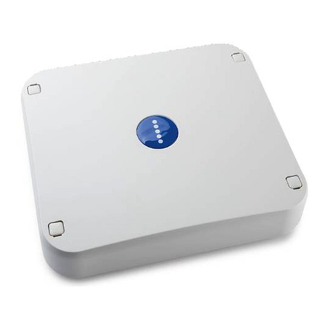
AddSecure CAT12CE User manual

60206560-100-SE I
AddSecure Smart Rescue AB
CAT12CE
Alarm transmitter
User manual

60206560-100-SE II
AddSecure Smart Rescue AB
No parts of this publication may be copied, redistributed or published by means of photocopying, electronic
copying or retransmission, printing or similar without the written consent of AddSecure Smart Rescue Nordic
AB.
AddSecure Smart Rescue Nordic AB reserves the right to change the publication or the products described in the
publication without prior notice.
All trademarks mentioned in the publication are the property of their respective owners.
Content
1Alarm transmitter CAT12CE .............................................................................................................................................4
1.1 Login............................................................................................................................................................................4
1.2 WEB interface..............................................................................................................................................................5
1.3 WEB interface, main parts...........................................................................................................................................5
2Users ....................................................................................................................................................................6
2.1 Add User......................................................................................................................................................................6
2.2 Change password ........................................................................................................................................................7
2.3 Delete User..................................................................................................................................................................7
3Connections ............................................................................................................................................................8
3.1 Ethernet connection....................................................................................................................................................8
3.2 Connection via GSM ....................................................................................................................................................9
3.3 Connection via Tetra modem....................................................................................................................................10
3.4 Connection of Pocsag................................................................................................................................................11
3.5 Connection via analog phone....................................................................................................................................12
4Alarm receiver .....................................................................................................................................................13
4.1 General information about Alarm Receivers .............................................................................................................13
4.1.1 Alarm via IP / GPRS. SOS Access v4.......................................................................................................................14
4.1.2 SMS message........................................................................................................................................................14
4.1.3 Tetra.....................................................................................................................................................................14
4.1.4 POCSAG ................................................................................................................................................................14
4.1.5 Email.....................................................................................................................................................................14
4.2 Add alarm receiver ....................................................................................................................................................15
4.3 Remove alarm receiver .............................................................................................................................................16
4.4 Alarm Receiver - Configuration .................................................................................................................................16
4.5 Add alarm path..........................................................................................................................................................17
4.5.1 Remove alarm path ..............................................................................................................................................17
4.5.2 Add alarm path IP address....................................................................................................................................18
4.6 E-mail - Configuration................................................................................................................................................19
4.7 SMS - Configuration...................................................................................................................................................20
4.8 Tetra - Configuration .................................................................................................................................................21
4.9 POCSAG Configuration ..............................................................................................................................................22
5Inputs ....................................................................................................................................................................23
5.1 Inputs 1-8 ..................................................................................................................................................................23
5.1.1 Configuration of input status................................................................................................................................25
5.1.2 Balanced input......................................................................................................................................................25
5.2 Input Sabotage ..........................................................................................................................................................26
5.3 Input V22M, SIA Modem...........................................................................................................................................27

60206560-100-SE III
AddSecure Smart Rescue AB
5.4 Input Alarm phone ....................................................................................................................................................28
5.5 Inputs. Tab: Status.....................................................................................................................................................29
5.6 Inputs. Tab: Extension card .......................................................................................................................................30
6Outputs ..............................................................................................................................................................31
6.1 General information about outputs ..........................................................................................................................31
6.2 Output status overview.............................................................................................................................................32
7System. ............................................................................................................................................................33
7.1 System. Tab: System..................................................................................................................................................33
7.2 System. Tab: System RS232 / RS485..........................................................................................................................35
7.3 System. Tab: Shared In/Out.......................................................................................................................................42
7.4 System. Tab: Time .....................................................................................................................................................43
7.5 System Tab: Configuration ........................................................................................................................................44
8Information ...........................................................................................................................................................45
8.1 Information. Tab: Info ...............................................................................................................................................45
8.2 Information. Tab: Event Log......................................................................................................................................46
9Software upgrade ..............................................................................................................................................47
10 SMS management..........................................................................................................................................................48
10.1 SMS messages...........................................................................................................................................................48
11 Document history...........................................................................................................................................................50
11.1 Audits ........................................................................................................................................................................50
11.2 Relaterade dokument................................................................................................................................................50
12 Notes................................................................................................................................................................................1

60206560-100-SE Sid: 4/51
AddSecure Smart Rescue
1ALARM TRANSMITTER CAT12CE
1.1 Login
Configuration for the ethernet connection on PC
to connect to - CAT12CE.
Click Start, type in the search box:
View network connections and click the icon.
Double-click Local Area Connection -
Properties - Internet protocol version 4.
Select Use the following IP address.
Fill in IP: 192.168.1.10
Subnet Mask:255.255.255.0
Press OK.
Now you can connect a network cable between the PC
and CAT12CE for programing via the WEB interface.
To configure alarm terminal CAT12 CE, a WEB interface is used located at the URL http://<CAT12CE ip address>.
(The default ip address is 192.168.1.100).
After the user enters this address in the WEB browser, a logon dialog opens with the following appearance:
Note: This window also opens automatically when the user resets or upgrades the device.
To access the alarm terminal object window, a User Name and password Lösenord must be entered.
Note: The alarm terminal comes with the following standard username and password, admin or admin..
These are used at the first login to the alarm terminal and are recommended to be deleted after the first new
user has been created and verified.
When approved User Name and Password are entered and the login is pressed, an information message is
displayed:
Successfully logged in, redirecting to main page.
If incorrect name or password has been entered, you receive the following error message:
Wrong username or password
If web interface access is not available within 5 minutes, session timeouts occur and you receive the following
error message:
Session timed out / not authenticated. Redirecting to login page

60206560-100-SE Sid: 5/51
AddSecure Smart Rescue
1.2 WEB interface
1.3 WEB interface, main parts
The WEB interface contains two main parts, on the right there is a menu to enter the different settings pages of
the alarm terminal and on the left is shown the content of the settings pages. The following buttons are in the
picture:
If the mouse pointer is transferred over any of the blue texts (the arrow switches to hand) alongside the slides,
you'll see quick information about what the button means.
•Flags - Used to select languages.
•Users - Add/change users.
•Connections - Settings of connection parameters.
•Alarm receiver - Configuration of alarm receivers.
•Inputs - Configuration of the alarm terminal inputs.
•Outputs - Configuration of the alarm terminal relay
outputs.
•System - Setting functions for sms-passwords, RS232
ports, etc.
•Info - Display of the status of the alarm terminal and event
log
•Upgrade - Software upgrade.
•Logoff - Exit of the web application.
In addition to these buttons, two buttons may appear on the
interface pages.
•OK - When the user wants changes made to be
saved/implemented, he clicks on this
button.
•Cancel - When the user does not want changes made to be
saved, he clicks on this button.

60206560-100-SE Sid: 6/51
AddSecure Smart Rescue
2USERS
This window is used to configure/change user and password settings.
•Logged in user - Currently logged in user
•Change password - This button opens a dialog in which logged-in users can change their password.
•Users - A list showing the user names created.
•Add User - This button opens a dialog for creating a new user (see next paragraph).
2.1 Add User
Any user can create additional users. A user account is used to change settings in the alarm terminal, create and
change passwords, etc.
To create a user account, the following steps must be completed:
1. Fill in the User Name field
2. In the Password field, type a new password
3. To confirm the new password, type it in the Password field again.
4. Click OK.
5. After a new user is created, you receive the following informational message:
User <name> successfully added

60206560-100-SE Sid: 7/51
AddSecure Smart Rescue
2.2 Change password
To change an already created user account, the following steps are performed:
1. Fill in the User Name field on the account.
2. In the Old Password field, type the old password.
3. To confirm the new password, type it in the Password field again.
4. Click OK. A dialog indicates that the password has been changed.
Password for user <user name> successfully changed
After the new password is saved, this can be used for authentication when the WEB page is to be opened the
next time. Please note that the user name and password supplied with the alarm terminal should be avoided.
2.3 Delete User
When a created user is to be removed from the terminal, click the delete icon to the right of the user name.
A window for acknowledging the deletion opens and you can press Ok to confirm deletion of the user, or Cancel
to abort the deletion.
Removal is confirmed by pressing OK. A dialog indicates removed user with text:
User <user name> removed
If you try to remove logged-in users, you receive the following error message:
Cannot remove currently logged user

60206560-100-SE Sid: 8/51
AddSecure Smart Rescue
3CONNECTIONS
Alarm terminal CAT12 CE can be connected to alarm receivers with two different alarm routes, primary and
secondary alarm path. The primary alarm route normally means that alarms are transmitted via Ethernet and
the secondary alarm route that alarms are transmitted via GSM modem.Secondary emergency route (back-up
route) is the route used when the primary connection is out of order.
When the WEB interface for connections is opened, the use of the drop-down menu to select the type of
connection in the Ansl via field.
3.1 Ethernet connection
The settings that can be made on this page refer to the indication of the IP address, Subnet Mask, and Standard
Gateway, Number of Retries, and Timeout..
Settings - Ethernet
•IP Address - The alarm terminal own IP address. The radio buttons select whether the addresses should be obtained
via DHCP or if static IP address should be used. (Note: The default setting is 192.168.1.100 when selecting a static IP
address.)
•Subnet mask - Subnet mask used to divide an IP address range into a number of subnets. (Used only for static IP
address)
•Default Gateway address - The network address used as a connection point when connecting to other networks.
(Used only for static IP address)
•Number of retries - Number of retries in case of failed connection, 2 retries are recommended and set by default.
If alarms cannot be transmitted, the queue is saved and sent as soon as CAT12CE has contact with the receiver again
•Timeout - Waiting time between retries if the alarm terminal does not receive receipt on sent alarm. The default and
recommended time is 10 seconds.
•Save –Saving changes for the page. If the button is not affected before the page is left, the changes are not saved.

60206560-100-SE Sid: 9/51
AddSecure Smart Rescue
3.2 Connection via GSM
When the WEB page for connections is opened, select in Interface using the GPRS drop-down menu.
•APN - Name - The name of the access point via GSM data.
AddSecure Link Telia mobiflex.ts.m2m
AddSecure Link, up to 1 GB: mobiflex.tele2.m2m
AddSecure Link, over 1 GB: mobiflex.4g.tele2.m2m
Maingate open network: maingate.telia.se
Maingate end network: maingatelan.telia.se
Maingate 500mb net: mg500mb.tmhlan7
Telia: online.telia.se
Tele2: internet.tele2.se
Telenor: internet.telenor.se
•Username - Used in conjunction with passwords to access the GPRS network. The name may be empty if it is not
specified for used SIM cards.
•Password - Used in conjunction with user name for access to the GPRS network. The name may be empty if it is not
specified for used SIM cards.
•PIN - Enter the SIM card PIN if used. The Sim card can be put in regular mobile phone to turn off pin control, not used
pin control, the field can be left blank.
•Advanced - Opens dialog for the indication of SMSC numbers and selection of network technology to use.

60206560-100-SE Sid: 10/51
AddSecure Smart Rescue
•Number of retries - The number of retries in case of failed transmission, 2 retries are recommended and set by
default.
•Timeout - Waiting time between retries if the alarm terminal does not receive receipt on sent alarm. Adjustable time
at least 40 seconds. The recommended time is 40 seconds. If alarms cannot be transmitted, it is saved in a queue and
sent as soon as CAT12CE has contact with the receiver again.
•Network status - Name of connected GSM Operator - Connected IP address - Signal level and Modem function, etc., i
s displayed in the middle part of the image when GPRS connection is established.
3.3 Connection via Tetra modem
If a Tetra modem is used to send alarms to Tetra terminals, you can see the status of the modem on this page.
•Service center Service Center number used to send message to MSISDN number
•Modem's ISSI TC8000 modem fixed number in the Tetra network
•Modem model Model of radio in the TC8000 modem
•Fw... Radio software version
•Number of retries the number of times CAT12CE will try to send a message if it does not succeed the first time
•Timeout between retries

60206560-100-SE Sid: 11/51
AddSecure Smart Rescue
3.4 Connection of Pocsag
Settings to handle POCSAG transmitters connected to CAT12CE via the rs485 port. POCSAG can be used to send
alarms to pagers.
•Transmitter frequency Displays the frequency of the transmitter used in paging. This value can be changed.
Select in the scroller to specify / display the frequency in MHz/kHz/Hz
•Numerik-id Unique identifier of the transmitter
•Network/Device Network specifies the network number of the POCSAG network. Device indicates device number in
the network (max 15)
•Info Displays the device status of the transmitter as an ex. current software

60206560-100-SE Sid: 12/51
AddSecure Smart Rescue
3.5 Connection via analog phone
Here you can set up audio on microphone and speakers for analog telephone line. This is the function of the
extension card Alarm phone / V22M. Activation of the function is done by selecting Alarm Phone / V22M in
menu Inputs\Extension card.
Below is the default connected phone setting.
•Volume speakers. Speaker volume to connected phone.

60206560-100-SE Sid: 13/51
AddSecure Smart Rescue
4ALARM RECEIVER
4.1 General information about Alarm Receivers
Alarms can be sent to one or more receivers.
Different types of alarm receivers can be configured to send different alarms.
Note! The receiver must be activated to start communication/polling. If this is not activated, no alarms will be
sent to this alarm receiver. This is achieved by marking the check box next to the alarm receiver's name.
Alarms –number: Here is listed the amount of alarms that are in queue and not yet sent to the alarm receiver.
If you want to clear this queue, to prevent the alarms from being sent, clear the check box next to the alarm
recipient's name. Note! Remember to activate the check box again if you want to re-establish communication
with the alarm receiver.

60206560-100-SE Sid: 14/51
AddSecure Smart Rescue
4.1.1 Alarm via IP / GPRS. SOS Access v4
Alarms via IP / GPRS are sent with the protocol SOS Access v4.
The alarm transmitter sends pings message for control of communication routes and alarms for various alarm
events e.g. activated alarm input.
Example.
CAT12CE communicates with Telecall alarm receiver
Primary alarm message route via Ethernet IP and secondary via GSM modem
4.1.2 SMS message
Alarms can be sent as SMS to any mobile number.
The alarm terminal can, if desired, be handled with SMS message from mobile phone. For detailed information
about the function, see SMS management page 42.
4.1.3 Tetra
Alarm events can be sent as SDS or Flash SDS to Rachel terminals. Both ISSI and MSISDN can be used.
4.1.4 POCSAG
Alarms can be sent via POCSAG to pagers
4.1.5 Email
E-mail can be configured to be sent to any email address in case of an alarm event. E-mail can only be sent via
ethernet connection.
-

60206560-100-SE Sid: 15/51
AddSecure Smart Rescue
4.2 Add alarm receiver
When adding a new alarm receiver, click Add new alarm receiver. The following dialog opens:
•TeleCall –Selected if alarms are to be sent to TeleCall alarm receivers. Since there are many emergency services that
use Telecall as receivers it is needed to ask the ARC for the specific IP addresses, etc.
•SOS –Selected if alarms are to be sent to SOS Alarm AB in Sweden. SOS has 2 receivers that are the same for the
whole country. Alarm routes with IP addresses, etc. are automatically configured when selecting SOS as the receiver.
•Securitas - Selected if alarms are to be sent to Securitas Sweden. Securitas has 2 receivers that are the same for
CAT12CE across the country. Alarm routes with IP addresses, etc. are automatically configured when selecting
Securitas as the receiver.
•RSGBG –Selected if alarms are to be sent to the Emergency Services of Gothenburg Alarm Fire Department Routes
and ip addresses are automatically configured when selecting RSGBG as the receiver.
•Nokas -Selects whether alarms are to be sent to Nokas Alarm Central Sweden. Alarm routes with IP addresses etc.
are automatically configured when selecting Nokas as the receiver.
•Stanley –Predefined parameters for sending alarms to Stanley Emergency Center. Balanced inputs or unbalanced
(On/Off). In both selections, rs232 CH-2 is set to EBL SIA for connection of serial communication with Ebl fire alarm.
•Tetra –Choice to send alarms to Rachel terminals, both ISSI and MSISDN can be used
•Custom –Selected if self-defined alarm receiver is added. The selection opens a dialogue for the name of the alarm
receiver. Alarm routes with IP addresses, etc. are manually configured with specific recipient data.
•SMS –Selected if alarms are to be sent as SMS to mobile phone(s).
•E-mail –Selected if alarms should be sent as E-mail
•POCSAG -Selected if alarms are to be sent to pagers

60206560-100-SE Sid: 16/51
AddSecure Smart Rescue
4.3 Remove alarm receiver
An existing alarm receiver is removed by clicking on the far right of each receiver's line.
Press OK in the confirmation dialog and the message that the alarm receiver has been removed will appear.
4.4 Alarm Receiver - Configuration
Access V4 alarm receiver configuration takes place in the following window
•Authentication - This field specifies the authentication code to use. (Obtained from alarm receiver).
•Request new authentication - This feature is standard checked and requests new authentication code from the alarm
receiver. When a new code is received, the orb turns green and the old code is no longer valid. This is a function that
reduces the risk that another transmitter can use the same Transmitter code and send incorrect alarms to the
receiver.
•Transmitter type - Type of alarm transmitter. (According to the alarm receiver's information).
•Transmitter code - Alarm transmitter code (transmitter ID, obtained by alarm receiver).
•Distribution - Here is the receiver (receiver) of the alarm. e.g. 36 for SOS Alarm in Gothenburg
•Pingrate - Ping interval setting to the alarm receiver. The first alarm path that is ok to the alarm receiver uses this
interval.
•All paths offline - Specify which output to activate by marking the relevant check box. Out 2 should be used for this
function. (Ut1 is used for operation indication, General system failure Ut4)

60206560-100-SE Sid: 17/51
AddSecure Smart Rescue
•Ethernet /GPRS - Path Configuration
▪Send path alarms –is checked if communication errors are to be sent to the recipient.
▪Path failed event –Alarm code used.
▪Distribution - Specifies the receiver (receiver) of the alarm. E.g. 36 for SOS Gothenburg
▪Additional info –Opens windows for additional information about the alarm, see 5.1 page 20 Extended alarm
info.
▪Filter time - Time to expire before the path alarm is sent.
▪Ethernet/GPRS offline: - Specify the output to be activated by marking the relevant box.( Ut1 is used for
operation indication, Out4 for general system failure)
4.5 Add alarm path
To add the alarm path, click Add Alarm Path. The following dialog opens:
Select the type of alarm path and click OK.The alarm route is confirmed by the following message:
Path successfuully added
4.5.1 Remove alarm path
An existing alarm route is removed by clicking on the remove icon for the alarm route.
A dialog to confirm the removal of the alarm path is shown and pressing ok confirms the removal. Cansel aborts
the action.

60206560-100-SE Sid: 18/51
AddSecure Smart Rescue
4.5.2 Add alarm path IP address
To add a new address for an alarm receiver, click on the config to the right of the affected alarm route.
The following dialog opens:
Configuring the alarm path
In this dialog you can configure:
•ARC-IP address - Specifies the recipient's IP address.
•ARC Port - Specifies the port number used.
•Encryption - Specifies whether (box checked) and how to use SSL encryption.
•Test alarm path –When the button is pressed, a test message is sent over the alarm route. This is not an alarm, only
a ping message to the recipient.

60206560-100-SE Sid: 19/51
AddSecure Smart Rescue
4.6 E-mail - Configuration
In configuration for the email function you can For the email
•Name - Name displayed in alarm receiver menu
•Transmitter - ID - Sender ID displayed in e-mail at the recipient.
•Sender address - Here you can enter the name of the sender. Address must be valid e-mail format.
Information for the remaining settings depends on the e-mail provider used.

60206560-100-SE Sid: 20/51
AddSecure Smart Rescue
4.7 SMS - Configuration
Configuration of SMS receivers.
•Name - Name displayed in alarm receiver menu
•Transmitter ID - Sender ID displayed in SMS at the recipient.
Add number.
•Name - Names that appear in the list of sms recipients.
•Number –Phone number to which SMS should be sent.
Table of contents
Other AddSecure Transmitter manuals
