manuals.online logo
Brands
  1. Home
  2. •
  3. Brands
  4. •
  5. Addvent
  6. •
  7. Fan
  8. •
  9. Addvent AVX 230 Series User manual

Addvent AVX 230 Series User manual

Installation Instruction for
the AVX 230/300 Range
T
elephone: 01179386400 Fax: 01179386401
Victoria Road Avonmouth Bristol BS11 9DB
077185 0908
Diagram 6 Electrical Connections
L
1
N
2
12
L
3
L
4
LIVE IN
NEUTRAL IN
230MP/300MP MODEL
230/300 BASIC MODEL
EXTRACT ONLY
230MP/300MP MODEL
230/300 BASIC MODEL
INPUT ONLY
L
1
N
2
12
L
3
L
4
LIVE IN
NEUTRAL IN
L
1
N
2
12
L
3
L
4
LIVE IN
NEUTRAL IN
230A/300A MODEL
EXTRACT ONLY
L
1
N
2
12
L
3
L
4
LIVE IN
NEUTRAL IN
230A/300A MODEL
INPUT ONLY
L
1
N
2
12
L
3
L
4
TYPICAL INTERNAL
WIRING LAYOUT
POWER
SUPPLY
NUMBER
TERMINALS
AVX230SN/AVX230WSN
AVX230PN/AVX230WPN
AVX230MPN/AVX230WMPN
EXTRACT ONLY
MODELS
AVX230AN/AVX230WAN
EXTRACT ONLY
AVX230SN/AVX230WSN
AVX230PN/AVX230WPN
AVX230MPN/AVX230WMPN
INPUT ONLY
MODELS
AVX230AN/AVX230WAN
INPUT ONLY
THROUGH A WINDOW (ALL MODELS DIAGRAMS 3/4).
1. Cut a hole in the glass to suit fan. This is best cut by a
qualified glazier, alternatively,
measure your window and get a new piece of glass with a pre-cut from your glass
merchant and replace.
2. Remove external grille by gently levering the top out with a
small screwdriver and remove the four pozidrive screws and
separate the two halves.
Hold the fan in position over the hole on the inside of the
window and then refit the four pozidrive screws from the
Outside.(Diagrams 1/2)
Caution –do not over tighten these screws as it is possible that you might crack
the glass, replace the external grille.
3. Electrical: All wiring must comply with current IEE Regulations. If in
any doubt call a qualified electrician.
NOTE: All flaps should open and close together. If they do not, remove the second
flap and remove and replace until it locates properly.
Connect the cable from the fan to a double pole fused spur having a contact
separation of at least 3mm in all poles, must be used and fitted with a 3 amp fuse,
and should be sited outside any room containing a shower or fixed bath. The fan
should not be accessible to a person using either the shower or the bath.
THROUGH WALL FIXING (ALL MODELS DIAGRAMS 1,2&5)
4. Cut a hole through the wall to suit fan and duct then fit the aluminium flexible duct
through the wall (wall fixing kit supplied separately - AVA295/230mm - AVA302/300mm)
making sure that there is a slight tilt to the outside in case any water gets in through the
external grille so it will not run into the room. Make good around the duct. If rigid duct
is used to install the fan it must be a minimum of 290mm long, if flexible duct is used
to install the fan it must be a minimum of 500mm (19 1/2 “) from the fan to the outlet
grille
Hole Size Ø
230mm 260 Ø
300mm 320 Ø
WARNING.
All window fan models are to be installed using a flexible supply cord and are supplied with a
supply cord with an internal cord anchorage.
All wall fan models are for fixed wiring only, a flexible cord must not be used.
WIRING DIAGRAM
For the 230AN/300AN model using the reversible 2 speed controller Part No.
AVACTRL2R and the variable, reversible speed controller part no. AVACTRLVRN
L
1
N
2
12
L
3
L
4
L
1
N
2
N
5
L
6
12
L
3
L
4
LIVE IN
NEUTRAL IN
230A/300A
EXTRACTOR FAN
REVERSIBLE
SPEED CONTROLLER
LIVE IN
NEUTRAL IN
VARIABLE LIVE EXTRACT
VARIABLE LIVE INPUT
IMPORTANT
When fitting a controller
(AVACTRL2R/AVACTRLVRN) remove
bridge wire from terminal block.
Diagram 7
230AN/300AN
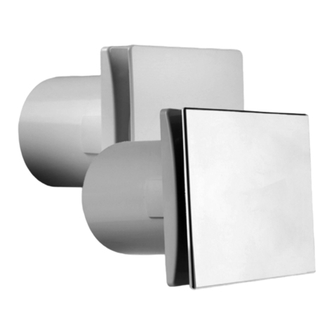
Diagram 1 External Grille
Diagram 5
5. Remove external grille by gently levering the top out with a small screwdriver and
remove the four pozidrive screws and separate the two halves. Hold against the
outside wall directly over the duct and drill and plug the fixing holes. Screw the grille
chassis to the wall and refit the grille. It is important to make sure that the two fixing
holes are one above the other to allow the lugs on the grille to fit properly into their
slots the right way up.
6. Remove the front grille concealing 2-fixing screws which secure the front grille
assembly to the main chassis. Remove these screws then carefully separate the two
halves.
Hold the body over the hole, first ensuring that the fan is level then mark four of the
six fixing holes available (one in each corner). Drill and plug these holes. Screw the
fan to the wall and refitthe front grille and replace screw caps.
7. Make the electrical connection as described in Paragraph 3.
If in any doubt call a qualified electrician.
8. Ratings as marked on fan label. T. Max 40oC
NOTE:
Do not install within a shower cubicle (Use our range of shower fans) or anywhere else
where there is a high risk of the fan being sprayed with water.
Fan to be fitted a minimum 2.3 metres from the floor.
Diagram 2 Rear of Fan with
grille removed
AUTO SHUTTER
INTERNAL FLAPS
AUTO GUARD
FIXING SCREWS
COVER
SCREWS
CABLE ENTRY
BACKCOVER
WITH GRILLE
THROUGH GLASS
FIXING TO FAN
CHASSIS
WINDOW
BACK COVER WITH GRILLE
CABLE ENTRY
AUTO GUARD FIXING SCREWS
AUTO SHUTTER INTERNAL
FLAPS
COVER SCREWS
WINDOW
THROUGH GLASS FIXING
TO FAN CHASSIS
THROUGH WALL FIXING
4mm - 32mm Glass
Cable Entry Cable
Entry
1.5A Two Core Cable
Cable Entry
IN
OUT
O
1.5m 5A Two Core Cable
D
B
Cable
Entry
Pull
Cord
C
A
THROUGH GLASS FIXING
SIDE ELEVATION
THROUGH GLASS
FRONT ELEVATION
4mm - 32mm Glass
Cable Entry Cable
Entry
1.5A Two Core Cable
FRONT ELEVATION
Cable Entry
IN
OUT
OUT
IN
1.5m 5A Two Core Cable
D
B
A
A
AB
A
Cable
Entry
Pull
Cord
C
C
CAUTION
Precautions must be taken to avoid the back-flow of gases into the room from the open
flue of gas or other open-fire appliances when mounted in outside windows or walls.
Key to dimensions / mm
230mm
300mm
A B C D
286 125 25 230
362 145 29 300
Diagram 4
Diagram 3
IMPORTANT :
Switch off mains supply before making any electrical connections. Installation
must be supervised by a qualified electrician.
This appliance is not intended for use by persons (including children) with
reduced physical, sensory or mental capabilities, or lack of experience and
knowledge, unless they have been given supervision or instruction concerning
use of the appliance by a person responsible for their safety. Children should be
supervised to ensure that they do not play with the appliance. Precautions must
be taken to avoid the back-flow of gases into the room from the open flue of gas
or other open-fire appliances when mounted in outside windows or walls.
Maintenance :Switch off mains supply and isolate the fan before carryout any
maintenance. The front cover can be removed and cleaned with warm soapy
water or polish. The fan impellor and the inside of the fan can be cleaned using a
warm damp cloth, care must be taken not to make the electrical connections wet.
It is recommended to check the electrical connections annually.

This manual suits for next models

1

Other Addvent Fan manuals

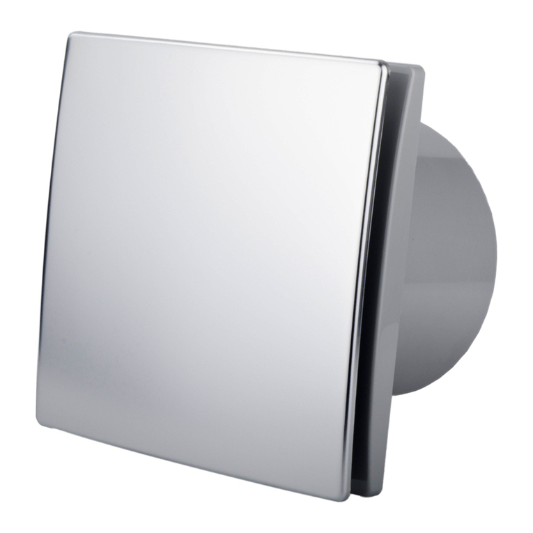
Addvent Elegance AVX100 User manual

Addvent

Addvent Elegance AVX100 User manual

Addvent AVX100EZS Assembly instructions

Addvent

Addvent AVX100EZS Assembly instructions

Addvent Elegance AVX100ES User manual

Addvent

Addvent Elegance AVX100ES User manual

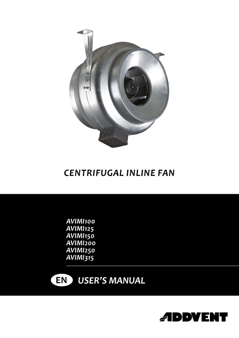
Addvent AVIMI100 User manual

Addvent

Addvent AVIMI100 User manual

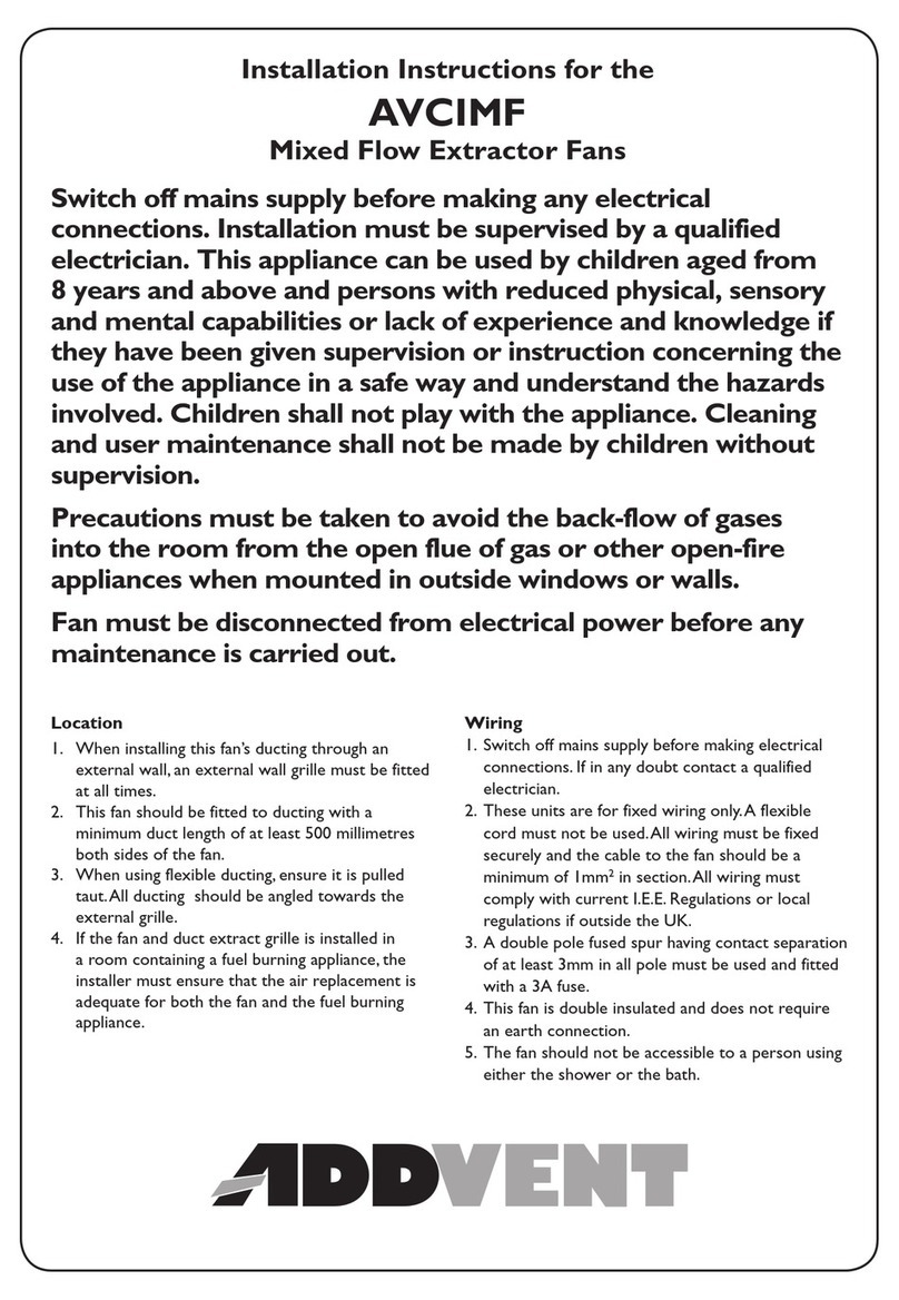
Addvent AVCIMF Series User manual

Addvent

Addvent AVCIMF Series User manual

Addvent AVX100WLED Instruction Manual

Addvent

Addvent AVX100WLED Instruction Manual

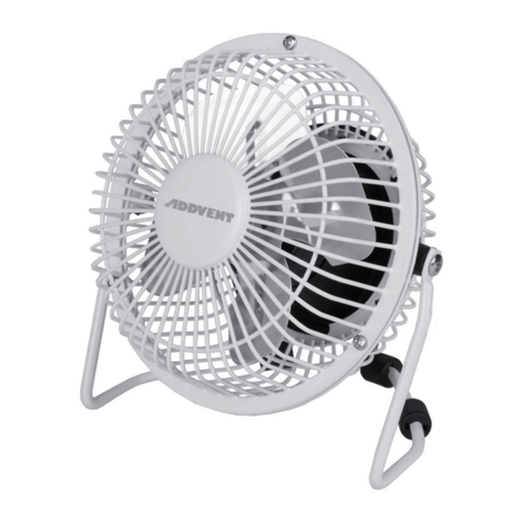
Addvent AVDF4 User manual

Addvent

Addvent AVDF4 User manual

Addvent AVAC18X User manual

Addvent

Addvent AVAC18X User manual

Addvent AVX100QS User manual

Addvent

Addvent AVX100QS User manual

Addvent Whisper Silent AVX100WT Instruction Manual

Addvent

Addvent Whisper Silent AVX100WT Instruction Manual

Addvent Elegance AVX100 User manual

Addvent

Addvent Elegance AVX100 User manual

Addvent AVX100WIDT User manual

Addvent

Addvent AVX100WIDT User manual

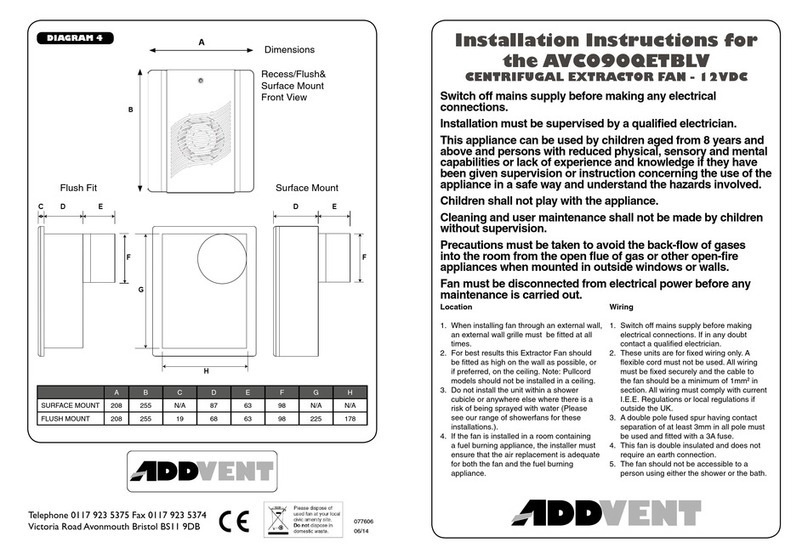
Addvent AVC090QETBLV User manual

Addvent

Addvent AVC090QETBLV User manual

Popular Fan manuals by other brands

Hunter Model Type 2 Owners and installation manual

Hunter

Hunter Model Type 2 Owners and installation manual

Meltem M-WRG-II M-U2 installation manual

Meltem

Meltem M-WRG-II M-U2 installation manual

Westinghouse Turbo Swirl owner's manual

Westinghouse

Westinghouse Turbo Swirl owner's manual

Bionaire BBLF01 instruction manual

Bionaire

Bionaire BBLF01 instruction manual

Kichler Lighting Compass 300322 instruction manual

Kichler Lighting

Kichler Lighting Compass 300322 instruction manual

Airflow LOOVENT eco T operating guide

Airflow

Airflow LOOVENT eco T operating guide

Bosch DRC97AQ50 User manual and assembly instructions

Bosch

Bosch DRC97AQ50 User manual and assembly instructions

Hunter 22068 Parts guide

Hunter

Hunter 22068 Parts guide

atomi smart AT2003 quick start guide

atomi smart

atomi smart AT2003 quick start guide

EGAmaster 79623 operating instructions

EGAmaster

EGAmaster 79623 operating instructions

Home Decorators Collection 91144 Use and care guide

Home Decorators Collection

Home Decorators Collection 91144 Use and care guide

Valueline VL-SFN16 manual

Valueline

Valueline VL-SFN16 manual

Wolf CRL Series Installation and maintenance instructions

Wolf

Wolf CRL Series Installation and maintenance instructions

Thermador HMWB30FS User and care manual

Thermador

Thermador HMWB30FS User and care manual

ORIGO SF-1603 instruction manual

ORIGO

ORIGO SF-1603 instruction manual

Fanco ORIGIN CFFCOR4KO installation manual

Fanco

Fanco ORIGIN CFFCOR4KO installation manual

Flex-a-Lite 775 installation instructions

Flex-a-Lite

Flex-a-Lite 775 installation instructions

Craftmade PAT64ABZC5 installation guide

Craftmade

Craftmade PAT64ABZC5 installation guide

manuals.online logo
manuals.online logoBrands
  • About & Mission
  • Contact us
  • Privacy Policy
  • Terms and Conditions

Copyright 2025 Manuals.Online. All Rights Reserved.