INSTALLATION
• Note:Installationassumestheunitandgrille
componentscanbeinstalledbeforethe
ducting.Iftheductingwillbeinaccessible
aftereitheroftheseareinplace,theopening
forthatcomponentshouldbeincreasedto
110mm,thiswillallowtheductingtopass
throughtheholeforattachment.Theducting
canthenbeinstalledrst.
Installing the isolating switch
and cables
1. Checktherearenoburiedpipesorcables
(e.g.electricity,gas,water)inthewallor
abovetheceilingwheretheisolatingswitch
andoperatingswitchistobelocated.Ifin
doubt,seekprofessionaladvice.
Wet rooms: the operating switch
must be situated so that it cannot
be touched by persons making use
of the bath or shower.
2. Isolatethemainssupply.
Warning: do not make any
connections to the electrical supply
at this stage.
3. Laythecablefromtheisolatingswitchtothe
transformerlocationviaanoperatingswitch.
4. Laythetwolengthsofsuitablyrated2
corecablefromthetransformertotheunit
location.
5. Laythecablefromtheisolatingswitchtothe
pointofconnectiontothemainssupply.
6. Installtheisolatingswitchandoperating
switchasperthemanufacturer’s
instructions.
7. Makeallconnectionswithintheisolating
switchandtheoperatingswitchonly.
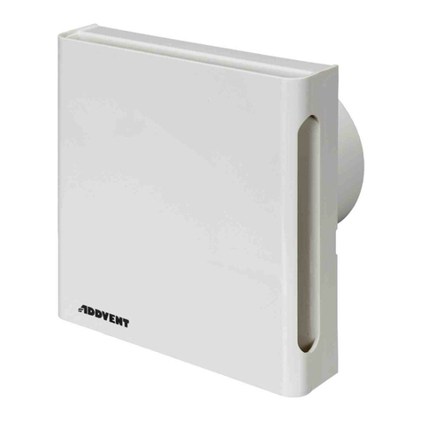
Installing the Whisper Silent
Shower Light Fan
1. Removethefrontcoverbydepressingthe
latchthroughtheslotonthesideofthe
coverandpullingaway.RefertoFigure3.
If working above ground floor
level, safety precautions must be
observed.
Mounting using the fixing screws and plugs:
2. Inserttheback-plateintothe100mmholein
thedesiredorientation.Orientatesothatthe
coverlatchreleaseslotiseasilyaccessible.
3. Markthecentresofthescrewholesand
cableentry.RefertoFigure4.
4. Removeback-plateanddrillholestothe
appropriatesizes.
5. Fitwallplugs(supplied),asrequired.
6. Repositionback-plateandsecurewith
screws(supplied).Takecarenotto
overtighten.
Mounting using the clamping brackets:
7. Inserttheback-plateintothe100mmhole
inthedesiredorientation.
8. Tightenthetwoclampingbrackets.Tighten
bothbracketsalittleatatimeuntilsecured.
9.
10.
Towireunit-RefertoWiringtheWhisper
Silent Shower Light Fan unit. Tore-fitthe
frontcover,firsthookinthe sideopposite
tothelatchandswing closeduntillatch
clipsintoplace.Ensure anywiringisnot
pinchedwhenclosing theunit.Donot
pressonthelightunitor outerfascia
cover;onlyapplypressure overthelatch.
InstallingtheExternalVentGrille
1. InserttheVentGrilleintothe100mmholein
thedesiredorientation.
2. Markthecentresofthescrewholes.
3. RemoveVentGrilleanddrillholestothe
appropriatesizes.
4. Fitwallplugs(supplied),asrequired.
5. RepositionVentGrilleandsecurewith
screws(supplied).
InstallingtheFlexibleDuct
1. Laytheductfromthebackoftheunittothe
externalventgrille.Pleaseensure:
- Anybendsarenotkinked.
- Fromthebackofunittheductshould
protrudeoutstraightforatleast60mmbefore
therstbend.Thisistoensurethatthe
backdraftapsarefreetoopenandclose.
- Aftertherstbendtheductruns
downwardssothatanycondensationthat
occursrunsouttowardstheexternalvent.
RefertoFigure5.
- Ductisfairlytautbutnotoverlystretched
thatthereisriskofpullingitselfawayfrom
eitherend.
2. Pushductingoverthebackoftheunitand
securewithtie-wraps.
3. Pushductingoverthebackoftheexternal
grilleandsecurewithtie-wraps.


