ADEMCO VIDEO RapidDome Operating instructions

RapidDome/RapidDome Gold MNRDRG120902US
Page 1 of 51
ADEMCO Video
Installation and Operation
Guide
RapidDome/RapidDome Gold
Document reference and revision – MNRDRG120902US

RapidDome/RapidDome Gold MNRDRG120902US
Page 2 of 51
Table Of Contents
Preface.....................................................................................................4
About the RapidDome/RapidDome Gold range .......................................4
Key Installation Features..........................................................................5
Safety instructions.................................................................................... 6
Safety instructions.................................................................................... 7
System Requirements...............................................................................8
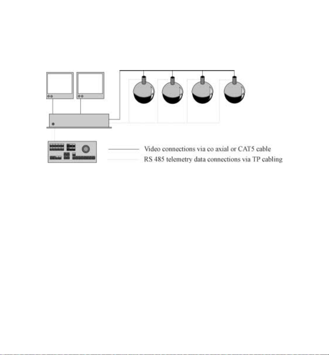
Basic System Example.............................................................................9
System Planning..................................................................................... 10
Example System Layout......................................................................... 11
Power Supply......................................................................................... 12
Power Supply Location.......................................................................... 13
Coaxial Video Cabling Specifications And Distances ............................ 14
Coaxial Video Cabling Notes................................................................. 15
CAT 5 Twisted Pair Video Cabling Background.................................... 16
CAT 5 Twisted Pair Video Cabling Specifications And Distances......... 17
Non CAT5 Cables.................................................................................. 17
CAT 5 Twisted Pair Video Cabling Notes.............................................. 18
RS 485 Twisted Pair Control Code Theory ............................................19
RS 485 Twisted Pair Control Code Termination ....................................20
RS 485 Twisted Pair Control Code Cabling ........................................... 21
RS 485 Twisted Pair Control Code Cables And Distances .....................23
RS 485 Control Code Wiring ................................................................. 24
Unpacking And Pre Assembly ............................................................... 25
Handling Acrylics.................................................................................. 25
Acrylic Cleaning.................................................................................... 26
Cable Termination External Units.......................................................... 28
Wiring tips ............................................................................................. 28

RapidDome/RapidDome Gold MNRDRG120902US
Page 3 of 51
External Wiring PCB Details ................................................................. 30
Internal Wiring PCB Details .................................................................. 31
Internal PCB Wiring Connections Table ................................................ 31
Internal Alarm Connections ................................................................... 32
Alarm Connector Socket Locations........................................................ 32
Internal Alarm Cable Details.................................................................. 33
Connection Table For Alarm Inputs and Outputs ................................... 33
Alarm Output Control ............................................................................ 34
Alarms To The RapidDome/RapidDome Gold Head Functionality........ 35
Alarms To The RapidDome/RapidDome Gold Head Function Table..... 35
Cable Termination Internal Units........................................................... 36
Power Up Precautions............................................................................ 36
Plug And Play Fitting............................................................................. 37
RapidDome/RapidDome Gold Initialization Process.............................. 38
Post Initialization ................................................................................... 38
Address Selection................................................................................... 40
Addressing Scheme................................................................................ 41
RS 485 Address Examples ..................................................................... 42
Pictorial Examples ................................................................................. 42
ADEMCO Video Address Table (First 32 addresses)............................. 43
RS 485 Termination Settings.................................................................. 44
Termination Hi / Low............................................................................. 44
RS 485 Termination Selection................................................................ 45
Control Code Protocol Selection............................................................ 47
Control Code Protocol Selection Table .................................................. 47
Equipment repair procedure ................................................................... 50

RapidDome/RapidDome Gold MNRDRG120902US
Page 4 of 51
Preface
This manual is intended as a complete reference for the installation of the
ADEMCO Video RapidDome/RapidDome Gold product range with all
mounting variants.
The manual’s approach is to describe the installation process in logical
order.
About the RapidDome/RapidDome Gold range
The RapidDome/RapidDome Gold range combines state of the art
technology with easy “plug and play” installation and the minimum of
engineer set up required.
The range features a number of camera and lens options including:
•Zoom lens ranges of 16x, 18x, and 22x.
•Camera options of color and exwave color/mono.
Please read this manual thoroughly before
attempting to install or operate the
RapidDome/RapidDome Gold unit.

RapidDome/RapidDome Gold MNRDRG120902US
Page 5 of 51
Key Installation Features
All variants of the RapidDome/RapidDome Gold include several powerful
features that make installation swift and straightforward.
•Dual control support with auto sensing on power up.
Either coaxial video control or RS 485 twisted pair data control code
are supported.
•Minimum of build required, not supplied as a kit of parts.
•Plug and play mounting, as easy as changing a light bulb.
•Integral video amplifier to allow matching over long cable runs.
•Alarm devices can be connected directly to the
RapidDome/RapidDome Gold head, 4 for RapidDome and 8 for
RapidDome Gold.
•Relay outputs available at the RapidDome/RapidDome Gold head, 1
for RapidDome, and 2 for RapidDome Gold.
•Storage of programmable settings in onboard battery backed RAM.
•Dual power capable, either 12vdc or 24vac.

RapidDome/RapidDome Gold MNRDRG120902US
Page 6 of 51
Safety instructions
RapidDome/RapidDome Gold units do not contain
hazardous levels of voltage but care must be taken when
wiring the unit, particularly the mains input to the unit’s
power supply.
Static sensitive devices are present in all units and anti
static precautions should be observed at all times
Improper or careless installation may cause irreparable
damage to the RapidDome/RapidDome Gold and
control equipment. Electrical installation should
conform to recognized national standards and
regulations.
Only qualified personnel should carry out installation and
servicing of RapidDome/RapidDome Gold units.
Never point the RapidDome/RapidDome Gold directly
towards a bright light source (e.g. the sun) for an
extended period of time.
Never expose the RapidDome/RapidDome Gold to light
intensive situations.
Permanent and irreparable damage to the camera’s pick
up device may result.

RapidDome/RapidDome Gold MNRDRG120902US
Page 7 of 51
Safety instructions
ADEMCO Video 2002
The information held within this manual and our
technical advice, whether verbal, in writing or by way
of trials is given in good faith but without warranty.
This also applies where proprietary rights of third
parties are involved.
Our advice does not release you from your obligation to
check its validity and to test our products’ suitability for
the intended purpose(s) and use(s).
The application, installation and use of our products
either in isolation or in conjunction with other products
used, provided and/or installed by you on the basis of
our technical advice are beyond our control and
therefore remain entirely your own responsibility.
ADEMCO Video products are sold in accordance with
our general terms and conditions of sale and delivery.
ADEMCO Video reserves the right to change the
design and specification of products and information
regarding products without notice.

RapidDome/RapidDome Gold MNRDRG120902US
Page 8 of 51
System Requirements
RapidDome/RapidDome Gold receive commands from the system
controller, this can be an ADEMCO Video matrix, an ADEMCO Video
Digital Recorder, or a third party controller.
If a third party controller is to be used, the controller
must support ADEMCO Video control code protocol,
or the RapidDome/RapidDome Gold must support the
third party controllers’ protocol.

RapidDome/RapidDome Gold MNRDRG120902US
Page 9 of 51
Basic Example System
Figure1
Figure 1 shows a possible system configuration.
A 2 monitor output ADEMCO Video matrix is used as the heart of the
control system and also sends and receives all control code information to
and from the attached RapidDome/RapidDome Gold units.
The system operator can select control of any one of the attached
RapidDome/RapidDome Gold domes with proportional speed pan and tilt
control via the keyboard joystick.
Alternatively the system can be left unattended with the
RapidDome/RapidDome Gold domes touring around selected presets.

RapidDome/RapidDome Gold MNRDRG120902US
Page 10 of 51
System Planning
Proper planning is an important aspect of any proposed CCTV system. A
system plan provides the installation engineers with a “blueprint” to work
to and also acts as an invaluable document for service engineers who
attend the system post sale for maintenance purposes.
Important considerations are:
•The RS 485 addresses of the RapidDome/RapidDome Gold shown
with the dome location.
•The RS 485 data cable route. This should clearly show where the daisy
chain begins and also where it ends. This is particularly important on
larger installations where multiple daisy chains are connected to one or
more RS 485 distribution units (part number ADCD8TP)
•The locations of all control equipment should be marked, particularly
where equipment is hidden from view, if a matrix is installed in a
roofspace for instance. This can save service time, as the service
engineer will not have to try to trace equipment by following the
cables!
•Cable junctions and mains supplies should also be included. Again the
main benefit is for the service engineer.
A very basic system plan is shown in figure 2 on the next page.

RapidDome/RapidDome Gold MNRDRG120902US
Page 11 of 51
Example System Layout
Figure 2

RapidDome/RapidDome Gold MNRDRG120902US
Page 12 of 51
Power Supply
Although the RapidDome/RapidDome Gold range is dual power capable
(12vdc / 24vac) it is recommended that all new installations are equipped
with the correct 24VAC supply.
Application type Part Number Specification
Indoor–1 per RapidDome
Indoor–Up to 8
RapidDome Series
Domes
PS1824
APS2408UL
24VAC 40VA
24VAC 24VA
External – One power
supply is required for one
external RapidDome
Series Dome unit. PS8024 24VAC, 80VA

RapidDome/RapidDome Gold MNRDRG120902US
Page 13 of 51
Power Supply Location
The power supply should be located as close to the
RapidDome/RapidDome Gold as possible for service and electrical
isolation purposes. This approach is not practical in all cases and the
power supply may in some cases have to be installed remote from the
RapidDome/RapidDome Gold location.
In situations where the power supply has to be installed remotely please
refer to the tables below for cable gauges and distances.
Maximum cable run length
AWG Indoor Feet/Meters Outdoor Feet/Meters
10 692/211 357/108
12 436/133 224/68
14 274/83 141/43
16 173/53 89/27
18 108/33 56/17
20 68/21 35/10
22 43/13 22/7
ADEMCO Video supports the figures shown in table
shown above for the stated cable gauges and distances.
Installation of cable gauges and distances that are
outside of the scope of this table are undertaken solely
at the installers’ risk and responsibility.

RapidDome/RapidDome Gold MNRDRG120902US
Page 14 of 51
Coaxial Video Cabling Specifications And Distances
The RapidDome/RapidDome Gold range are capable of delivering crisp,
clear video images over Coaxial cable runs of up to 2,300 feet, (700
meters).
A video amplifier is fitted as standard to all RapidDome/RapidDome Gold
units to allow adjustment for correct video levels and quality over any
length of cable run up to 2,300 feet (700 meters).
The RapidDome/RapidDome Gold unit is capable of transmitting video
over a good specification Coaxial cable run of up to 1,000 feet (300
meters) without adjustment to the video amplifier.

RapidDome/RapidDome Gold MNRDRG120902US
Page 15 of 51
Coaxial Video Cabling Notes
There are a number of precautions that must be considered before running
the Coaxial cables to minimise the possibility of problems with the video
signal.
The quality and specification of the cable used will
have a direct affect on the quality of the video signal at
the control equipment end of the system.
Compromising the cable quality and specification can
lead to poor video quality and system performance
Always keep Coaxial cables away from all other cables
and run them in complete isolation wherever possible.
Never run the cables close to potential sources of
electromagnetic interference such as motors, dimmers
and high-speed data trunk cables.
When other cables cannot be avoided run across them,
not alongside and keep this distance as short as
possible.

RapidDome/RapidDome Gold MNRDRG120902US
Page 16 of 51
CAT 5 Twisted Pair Video Cabling Background
Most RapidDome/RapidDome Gold mountings feature built in UTP
transmission modules. This provides the option of cabling the video signal
down a single twisted pair of a CAT5 multipair cable, instead of
traditional Coaxial cable.
CAT5 is a short term for “category 5”, which is the electrical specification
for a range of twisted pair cables that are commonly used for Ethernet
installation.
CAT5 cabling for video transmission allows multiple cameras to be
transmitted down the same multicore CAT 5 cable without inter camera
video interference or crosstalk.
When installing CAT5 cable there are some good practice considerations:
•Observe the warning rules as for Coaxial cables that are stated in the
previous section.
•If you run a separate CAT5 specifically for CCTV ensure that it is
clearly identified, to prevent confusion with network and other
structured cabling.
•Use “Krone” type junction boxes where CAT5 joints are necessary.
These boxes are supplied with labelling for all terminals. A special
tool is required to insert cables into Krone junction terminals.

RapidDome/RapidDome Gold MNRDRG120902US
Page 17 of 51
CAT 5 Twisted Pair Video Cabling Specifications And Distances
The table below shows distances and ADEMCO Video UTP options to
suit most RapidDome/RapidDome Gold units.
Distance Receiver model and description Coaxial video
control code
Up to 500
feet
(150meters)
ATP212A video transceiver
Cable must be within the same building as
there is no transient protection.
Yes
Up to 1000
feet
(300meters)
ATP213A video transceiver
ATP1613A 16 port passive hub Yes
Up to
3,000 feet
(1,000
meters)
ATP652R Active receiver
ATP1662R 16 port active receiver No.
Control code
must be via
RS 485 using
another pair
Non CAT5 Cables
It is possible to run NVT via two other non-CAT5 cable specifications in
existing installations:
•Telephone specification CW1308, internal applications.
•Telephone specification CW1128, external applications.

RapidDome/RapidDome Gold MNRDRG120902US
Page 18 of 51
CAT 5 Twisted Pair Video Cabling Notes
Important notes that you must observe when installing with CAT5 cable
and ADEMCO Video UTP receiving equipment.
Coaxial video control code is possible when a passive
ADEMCO Video receiver module or hub is used at the
control end of the system. If an active receiver is used
at the control endof the system RS 485 control code
must be used, this will require another single twisted
pair per camera.
An ADEMCO Video receiver module must be used at
the control end of the system for every camera that is
transmitting video via CAT5. An ADEMCO Video
hub can be used to receive up to 16 cameras via CAT5.
When wiring via twisted pair always ensure that you
are actually using a twisted pair by examining the
cable. Failure to use wires form the same pair will lead
to noise introduction and subsequent video and control
code problems.
The CAT5 cable used must not be screened in any
way, either by foil, braided screen or any other means.
The use of any cable other than unscreened CAT5 may
lead to a reduction in performance and is solely the
responsibility of the installer.

RapidDome/RapidDome Gold MNRDRG120902US
Page 19 of 51
RS 485 Twisted Pair Control code Theory
RapidDome/RapidDome Gold units will only deliver the full feature set
when using RS 485 twisted pair control code in conjunction with an
ADEMCO Video control code matrix controller.
When using RS 485 twisted pair control code the video signal is
transmitted via a Coaxial or CAT5 twisted pair cable and the control code
information is sent as data via another twisted pair cable.
RS 485 twisted pair control code cabling is installed and wired as a
network that comprises of one or more daisy chains. When more than one
daisy chain is installed an RS 485 control code distribution unit must be
installed to broadcast control code data across the entire RS 485 network,
part number
(ADCD8TP). Multiple distribution units can be installed on the RS 485
network to allow for complex wiring arrangements.
Star wiring is not permitted as it makes the correct
termination of the RS 485 network impossible.
Star wiring is basically multiple daisy chains that are
connected at one common point; the (ADCD8TP code
distribution unit provides the correct means of
supporting star wiring.

RapidDome/RapidDome Gold MNRDRG120902US
Page 20 of 51
RS 485 Twisted Pair Control code Termination
The RS 485 control code network requires termination at the first device
in the daisy chain and also the last device in the daisy chain.
The first device is always the control code controller and has RS 485
termination as standard and there is no need for this device to be
unterminated. The RapidDome/RapidDome Gold domes represent other
devices on the network and only the end of line RapidDome/RapidDome
Gold should have the termination selected as “on”. All
RapidDome/RapidDome Gold domes between the first and last device
should have the termination selected as “off”.
This manual suits for next models
1
Table of contents
Other ADEMCO VIDEO Outdoor Camera manuals