ADEO SCREEN PROFESSIONAL User manual

PROFESSIONAL Installation Manual
Made by Adeo Screen Sp. Z o.o. (Poland)
Doc: PROFESSIONAL Installation Manual rev2 | 13.06.2017
Model PROFESSIONAL
Code PRONPROFESSION-XXXXX
Manuale d’installazione e d’uso schermo avvolgibile
Rolling screen installation and operation manual
Manuel d’installation et d’utilisation de l’écran de projection
Bedienungs- und Installationsanleitung: Motorleinwand
Manual de instalación y uso de la pantalla enrollable
Instrukcja montażu i obsługi ekranu rozwijanego

ITALIANO - Manuale d’installazione e d’uso schermo avvolgibile
Made by Adeo Screen Sp. Z o.o. (Poland) Specifications are subject to change without notice. E&OE
Doc: PROFESSIONAL Installation Manual rev2 | 13.06.2017
Please verify that you are working with the latest revision of this document before specifying your screen.
Page 2
01 INTRODUZIONE
Il presente manuale è parte integrante del prodotto e la sua lettura e comprensione sono di fondamentale importanza per la sicurezza. In esso sono descritte le norme e le modalità di
impiego che consentiranno al cliente un corretto e sicuro uso dello schermo. Il manuale deve sempre accompagnare il prodotto e va custodito con cura in luogo idoneo a garantirne
l’integrità fisica e facilmente accessibile a chiunque sia autorizzato alla sua consultazione. Ogni utilizzatore del prodotto è responsabile della salvaguardia del manuale. L’utilizzatore è
inoltre responsabile del controllo della funzionalità dello schermo e della riparazione o sostituzione di parti soggette ad usura che potrebbero causare danni.
Le immagini contenute in questo manuale hanno lo scopo di descrivere in maniera dettagliata funzioni, caratteristiche o procedure. Tuttavia possono differire per il tipo di modello
rappresentato, questo non comporta modifiche al significato descrittivo dell’immagine.
02 NORME GENERALI DI SICUREZZA
ATTENZIONE: Importanti istruzioni di sicurezza. Attenersi alle istruzioni poiché l’installazione impropria può provocare gravi ferite. Assicurarsi sempre di aver letto e compreso
bene le istruzioni e le avvertenze contenute in questo manuale prima di iniziare ad utilizzare il prodotto e di effettuarne qualsiasi intervento di manutenzione.
- Divieto assoluto di installare gli schermi sopra zone di possibile transito di persone. Controllare, prima e durante l’utilizzo, che lo schermo non generi situazioni pericolose.
- Non manomettere, togliere o danneggiare nessun elemento o parte dello schermo.
- Non eseguire mai operazioni di manutenzione sullo schermo con motore acceso (Per una maggior sicurezza, togliere l’alimentazione).
- Obbligatorio scollegare l’alimentazione durante la pulizia, la manutenzione o quando si sostituiscono delle parti.
- Divieto assoluto di utilizzo del prodotto ai bambini. Divieto assoluto di far avvicinare bambini allo schermo durante il suo movimento.
Ogni schermo è coperto da garanzia, la cui validità dipende dall’effettivo rispetto ed esecuzione delle istruzioni contenute in questo manuale.
ATTENZIONE: I kit d’installazione di ogni schermo, non contengono viti e tappi a espansione per il fissaggio alle pareti/soffitti. L’installatore è responsabile della scelta
adeguata di viti e sistemi di fissaggio, in base alle differenti tipologie di materiale delle pareti o soffitti sui quali deve installare lo schermo.
Un’installazione errata può compromettere la sicurezza delle persone che useranno il prodotto, il produttore non è responsabile per danni a cose o persone causati da
installazione errata, uso improprio dello schermo, scarsa o insufficiente manutenzione.
Il produttore non è responsabile di problemi legati ad errori d’installazione. Se necessario contattare il nostro ufficio tecnico per eventuali chiarimenti.
L’installazione dello schermo, i collegamenti elettrici e le verifiche in caso di malfunzionamento degli avvolgimenti motorizzati devono essere eseguiti dal rivenditore
autorizzato o da personale competente e a conoscenza dei rischi che può presentare l’energia elettrica. Il cavo di collegamento non può essere sostituito. Se il cavo è
danneggiato lo schermo deve essere sostituito. La manomissione dei fine corsa o la foratura del sigillo posto sopra i fori comporta la decadenza della garanzia.
FINITO IL MONTAGGIO DELLO SCHERMO SULLE STAFFE E’ OBBLIGATORIO VERIFICARE LA PERFETTA ORIZZONTALITA’ PRIMA DELL’UTILIZZO.
03 AVVERTENZE E PRECAUZIONI PER L’UTILIZZO E INSTALLAZIONE
Gli schermi sono indicati per utilizzi in ambienti interni con condizioni di temperatura (20 - 25 °C) ed umidità normali.
Assolutamente vietato di installare gli schermi fronte finestre e di utilizzarli come oscuranti, vietato installare lo schermo in prossimità di fonti di calore o freddo quali caminetti condizionatori o termosifoni, il
mancato rispetto di questi divieti potrebbe comportare deformazioni o allungamenti permanenti del tessuto di proiezione.
L’utilizzo dello schermo motorizzato all’esterno prevede l’adozione di particolari precauzioni quali:
1- Protezione del cavo/i di alimentazione del motore dalle radiazioni UV, con adeguate canaline o guaine idonee all’installazione esterna.
2- Utilizzo di passacavi per l’isolamento all’acqua e umidità nelle giunzioni con le scatole portafrutti o derivanti.
3- Utilizzo di commutatori con grado di protezione IP55 o superiore (il commutatore di serie al prodotto non è conforme all’utilizzo esterno).
4- Copertura e relativa protezione dello schermo dal contatto diretto con acqua o liquidi
Non lasciare esposto per lunghi periodi il telo di proiezione alla luce solare per prevenire l’ingiallimento dello stesso (verificare anche che, a causa dell’ esposizione alla luce solare, lo schermo non raggiunga
i livelli di temperatura sopra indicati).
Poiché il materiale di cui è composto il telo di proiezione (PVC) tende a caricarsi elettrostaticamente, una presenza eccessiva di polveri nell’ ambiente di proiezione può provocare un degrado delle qualità
ottiche del telo a causa della deposizione delle polveri per attrazione elettrostatica (vedi anche pulizia del telo di proiezione).
Si premette che l’utilizzo dello schermo avvolgibile prevede la completa apertura del tessuto (discesa) e successivamente al suo utilizzo con proiettore, la completa chiusura del tessuto (salita). La completa
apertura e chiusura (discesa-salita) dello schermo viene indicato come “ciclo”.
Gli schermi avvolgibili motorizzati sono indicati per utilizzi a “ciclo” unico, questo significa che fra un ciclo e l’altro viene normalmente lasciato passare un notevole lasso di tempo. Non è previsto l’utilizzo
dello schermo con continue aperture e chiusure.
I motori utilizzati negli schermi, sono provvisti di sistemi di bloccaggio termico che permette di non surriscaldare il motore danneggiandolo in modo permanente. L’attivazione del blocco termico avviene dopo
un certo numero di cicli di utilizzo, il numero di cicli varia in base al tipo di motore e al tipo di schermo (normalmente fra 3 e 6 cicli). Si precisa comunque che il calore emesso dal motore viene trasmesso al
rullo e di conseguenza al tessuto avvolto sul rullo. Il surriscaldamento del tessuto può provocare deformazioni o allungamenti non omogenei permanenti con conseguenti disallineamenti del fondale o
deformazioni del tessuto.
Allo scopo di evitare quanto precedentemente descritto si fa divieto assoluto di utilizzare lo schermo superando 3 cicli completi di utilizzo (salita-discesa). Al raggiungimento del 3 ciclo di utilizzo continuo o a
tempi ravvicinati, sarà necessario attendere 40min con lo schermo in posizione aperta ( tessuto srotolato) per permettere il raffreddamento del motore e relativi componenti strutturali, prima di un nuovo
utilizzo.
ATTENZIONE: Non forzare manualmente la fuoriuscita del telo perché potrebbe provocare danni al motore o il distacco del cassonetto di contenimento dalle staffe di fissaggio.
Non permettere ai bambini di giocare con i dispositivi di comando fissi. Tenere i telecomandi lontano dai bambini.
Osservare lo schermo in movimento e tenere lontane le persone finché lo schermo non sia completamente chiuso.
E’ vietato, bloccare, impedire e forzare il movimento dello schermo, aggrapparsi o dondolarsi , aggiungere o applicare qualunque oggetto al telo o fondale, modificare la struttura dello schermo; in quanto
potrebbe causare danni al sistema di avvolgimento con conseguenti danni a cose e persone.
Divieto assoluto di installare lo schermo fronte finestre e l’utilizzo di esso come oscurante.
Divieto assoluto di installare lo schermo in prossimità di fonti di calore o freddo quali caminetti condizionatori, termosifoni o similari.
Installare lo schermo tassativamente in bolla.
SMALTIMENTO DEL PRODOTTO
Come per le operazioni d'installazione, anche al termine della vita di questo prodotto, le operazioni di smantellamento devono essere eseguite da personale qualificato.
Questo prodotto è costituito da vari tipi di materiali: alcuni possono essere riciclati, altri devono essere smaltiti. Informatevi sui sistemi di riciclaggio o smaltimento
previsti dai regolamenti vigenti nel vostro territorio, per questa categoria di prodotto.
Come indicato dal simbolo a fianco è vietato gettare questo prodotto nei rifiuti domestici. Eseguire quindi la "raccolta separata" per lo smaltimento, secondo i metodi
previsti dai regolamenti vigenti nel vostro territorio, oppure riconsegnare il prodotto al venditore nel momento dell'acquisto di un nuovo prodotto equivalente.
Attenzione: i regolamenti locali possono prevedere pesanti sanzioni in caso di smaltimento abusivo di questo prodotto.

ITALIANO - Manuale d’installazione e d’uso schermo avvolgibile
Made by Adeo Screen Sp. Z o.o. (Poland) Specifications are subject to change without notice. E&OE
Doc: PROFESSIONAL Installation Manual rev2 | 13.06.2017
Please verify that you are working with the latest revision of this document before specifying your screen.
Page 3
04 CARATTERISTICHE GENERALI DEL PRODOTTO
Lo schermo prodotto è costruito in conformità con le disposizioni delle seguenti direttive CE: 2014-35-CE LDV Bassa tensione
2014-30-EU EMC Compatibilità elettromagnetica
2014-53-CE Apparecchiature radio
2009-125-CE CONSUMI Eco design
2011-65-CE ROHS Sostanze pericolose
2012-19-CE RAEE Trattamento rifiuti
2001-95-CE SICUREZZA Prodotti sicuri
Lo schermo descritto nel presente manuale deve essere utilizzato solo ed esclusivamente come supporto per la videoproiezione. Qualsiasi altro uso non previsto da questo manuale, non è acconsentito.
Lo schermo contiene uno o più tessuti/fogli di proiezione in PVC plastificato senza cadmio oppure in FIBRA di VETRO impregnata di PVC plastificato, ogni tessuto può essere classificato di categoria:
-M1 o M2 secondo la regolamentazione Francese (LNE Laboratoire national de métrologie et d’essais – SME Centre de recherches du Bouchet - WARRINGTONFIRE GENT Laboratoire de
métrologie et d’essais –IFTH Laboratoire accreditè )
-B1 o B2 secondo la regolamentazione Tedesca (LNE Laboratoire national de métrologie et d’essais – SME Centre de recherches du Bouchet - WARRINGTONFIRE GENT Laboratoire national de
métrologie et d’essais)
-UL94HB secondo la regolamentazione degli Stati Uniti D’America (THE GOVMARK Organization, Inc.)
Poiché non esiste ancora a livello europeo una armonizzazione tra le varie normative nazionali di classificazione si esplicita che la classe M1 francese corrisponde a materiale non infiammabile e la
classificazione M2 corrisponde a materiale non facilmente infiammabile.
I tessuti/fogli di proiezione contenuti e utilizzati sugli schermi sono costituiti principalmente da PVC plastificato o fibra di vetro plastificata, tali tessuti sono sensibili a temperatura e umidità, per tale motivo
la tolleranza dimensionale accettata è del’1% su ogni dimensione.
Le tolleranze sui profili in alluminio utilizzati sono di +/-2 mm.
Le tolleranze sull’ingombro totale sono di:
-+/- 3 mm fino a 2500 mm di ingombro totale;
-+/- 5 mm fino a 4000 mm di ingombro totale;
-+/- 10 mm fino a 8000 mm di ingombro totale;
-+/- 20 mm fino a 16000 mm di ingombro totale;
-+/- 30 mm fino a 24000 mm di ingombro totale.
05 PULIZIA MANUTENZIONE
Lo schermo e i tessuti di proiezione degli schermi sono delicati, quindi bisogna prestare particolare attenzione e seguire le seguenti istruzioni per la loro pulizia:
Non utilizzare mai solventi, prodotti chimici o abrasivi o strumenti appuntiti per pulire la superfice.
Evitare qualsiasi contatto con altri materiali (vernici, inchiostri ect) in quanto potrebbe essere impossibile rimuoverli dal tessuto.
TESSUTI DI PROIEZIONE VISION, REFERENCE, HELIOS: Per pulire telo di proiezione, utilizzare un panno morbido, pulito, inumidito, eventualmente abbinato con detergenti a base neutra o alcool. Poiché dopo
la pulizia potrebbe verificarsi che il telo si carichi di elettricità statica, a causa dello sfregamento con il panno, si consiglia di passare, con un panno pulito, un liquido antistatico sul telo per evitare che la
polvere venga nuovamente attratta dallo stesso.
PROFILI GENERICI: Per pulire il profilo spolverare utilizzando un panno morbido pulito ed eventualmente dei detergenti non aggressivi.
PROFILI VELLUTATI: Per pulire il profilo spolverare utilizzando un panno morbido pulito o spazzole con sedole morbide e antistatiche. E’ acconsentito utilizzare un spazzola installata su aspirapolvere solo se le
setole sono morbide e perfettamente pulite.
STRUTTURA e STAFFE DI FISSAGGIO: E’ obbligatorio verificare periodicamente lo stato del prodotto e la tenuta delle sue staffe di fissaggio. In caso di presenza di deformazioni, lacerazioni o cedimenti
strutturali di staffe viti o componenti del prodotto, è obbligatorio mettere immediatamente in sicurezza la zona circostante lo schermo, per evitare qualsiasi tipo di danno a cose e persone. Successivamente è
obbligatorio provvedere all’immediata sosituzione del presunto componente difettoso e al ripristino del prodotto.
06 DISIMBALLO DELLO SCHERMO E MOVIMENTAZIONE PRODOTTO
Assicurarsi che nessuna parte dello schermo sia stata danneggiata durante il trasporto. In caso di anomalia comunicarlo tempestivamente al rivenditore. Verificare che siano presenti tutti gli accessori per
tipo di schermo descritti nel manuale.
Schermo avvolgibile motorizzato o Radio integrato
Schermo avvolgibile arganello
-1 Kit con 2 staffe per l’installazione (per schermi fino alla larghezza di 3mt)
-1 Kit con 3 staffe per l’installazione (per schermi oltre alla larghezza di 3mt)
-1 commutatore unipolare 10°, 250V uomo presente con frecce direzionali, compreso di calotta per montaggio a parete
-1 trasmettitore a radio frequenza (per schermi versione radio integrato)
-1 chiave esagonale in plastica
-1 libretto istruzioni
(non compresi viti e tasselli per parete)
-1 Kit con 2 staffe per l’installazione (per schermi fino alla larghezza di 3mt)
-1 Kit con 3 staffe per l’installazione (per schermi oltre alla larghezza di 3mt)
-1 asta comando
-1 libretto istruzioni
(non compresi viti e tasselli per parete)
ATTENZIONE non usare taglierini o oggetti appuntiti per aprire l'imballo, utilizzare sempre guanti di protezione durante l’apertura dell’imballo e l’installazione o movimentazione del prodotto. Movimentare
e installare il prodotto minimo in due tre o quattro persone in base al peso del prodotto (valori di riferimento per carico propersona: 25kg maschio - 15kg femmina). In caso di pesi superiori si raccomanda
di utilizzare attrezzatura di sollevamente specifica.

ITALIANO - Manuale d’installazione e d’uso schermo avvolgibile
Made by Adeo Screen Sp. Z o.o. (Poland) Specifications are subject to change without notice. E&OE
Doc: PROFESSIONAL Installation Manual rev2 | 13.06.2017
Please verify that you are working with the latest revision of this document before specifying your screen.
Page 4
07 ISTRUZIONI PER L’INSTALLAZIONE
ATTENZIONE: E’ assolutamente vietato installare lo schermo su pareti mobili o cavi instabili, le staffe devono essere applicate su superfici che garantiscono nel tempo la distanza fra
una staffa e l’altra. L’installazione dello schermo deve essere effettuato con viti e tasselli adeguati al peso e alla tipologia di parete o soffitto sulle quali si vuole fissare le staffe, prima
di incominciare l’installazione scegliete il tipo di tassello o fissaggio seguendo lo schema seguente:
Schermo con larghezza fino a cm
160
200
250
300
360
410
520
620
Peso complessivo da considerare
Kg 20
Kg 25
Kg 30
Kg 35
Kg 45
Kg 50
Kg 100
Kg 150
INSTALLAZIONE A PARETE:
inserire la vite 4 con la filettatura rivolta verso l’alto nella placca 1 ed avvitare un poco il dado 3 lasciando 4-5 mm di lasco; agganciare la placca 1 al
cassonetto e inserire lo spinotto in plastica 2 nello scanso della staffetta. Va sottolineato che, ai fini del solo montaggio , è indifferente se si monta la placca
in un verso piuttosto che nell’ altro essendo i profili di aggancio del cassonetto perfettamente simmetrici. Fissare a parete la staffa 5 con tasselli a
espansione adeguati al tipo di muro (minimo Ø 8 mm) e fissare la placca 1 con la staffa 5 usando la rondella 7 e il bullone 3.
INSTALLAZIONE A SOFFITTO:
fissare le staffe a soffitto 6, fornite di serie con lo schermo, con tasselli a espansione adeguati al tipo di muro (minimo Ø 8 mm), a circa 10 - 15 cm dalle
estremità del cassonetto. Per gli schermi di larghezza superiore ai 350 cm la terza staffa viene posizionata al centro del cassonetto. inserire la vite 4 con la
filettatura rivolta verso l’alto nella placca 1 ed avvitare un poco il dado 3 lasciando 4-5 mm di lasco; agganciare la placca 1 al cassonetto e inserire lo
spinotto in plastica 2 nello scanso della staffetta. Fissare la placca 1 con la staffa 6 usando la rondella 7 e il bullone 3.
installazione a soffitto direttamente con le placche di fissaggio:
E’ possibile installare a soffitto direttamente le placche di aggancio 1 se si desidera che il cassonetto sia il più possibile aderente al soffitto (attenzione: per
effettuare con facilità e rapidità tale installazione è richiesta una ottima planarità del soffitto in oggetto nonché un perf etto allineamento delle placche).
Fissare le placche con tasselli a espansione deguati al tipo di soffitto (minimo Ø 8 mm), a circa 10 - 15 cm dalle estremità del cassonetto. Per questo tipo di
montaggio il lato della placca per lo spinotto di fissaggio va, di norma, rivolto verso il lato anteriore del cassonetto per permettere un facile inserimento dello
spinotto. Verificare in modo accurato l'allineamento e la orizzontalità delle placche. Allo scopo si possono utilizzare degli spessori tipo le rondelle metalliche
incluse nella confezione. Attenzione che dalla accuratezza di tale operazione dipende la velocità e la facilità del successivo aggancio del cassonetto alla
placca. Per gli schermi di larghezza superiore ai 350 cm la terza placca viene posizionata al centro del cassonetto. Inserire il cassonetto nelle placche con un
movimento semirotatorio (inserimento a scatto) ed infilare gli spinotti di plastica che assicurano il fissaggio del cassonetto alle placche.
INSTALLAZIONE CON STAFFE A SISTEMA RAPIDO:
1) fissare con tasselli a espansione adeguati (minimo Ø 8 mm) le staffe (è possibile il fissaggio a soffitto o a parete) controllando il loro livellamento;
2) fissare lo schermo alle staffe seguendo le figure a sinistra
08 REGOLAZIONE CONTRAPESO TENSIONATURA (solo per versione TENSIO; no TENSIO CLASSIC )

ITALIANO - Manuale d’installazione e d’uso schermo avvolgibile
Made by Adeo Screen Sp. Z o.o. (Poland) Specifications are subject to change without notice. E&OE
Doc: PROFESSIONAL Installation Manual rev2 | 13.06.2017
Please verify that you are working with the latest revision of this document before specifying your screen.
Page 5
09 IDENTIFICAZIONE TIPO MOTORE –CARATTERISTICHE –COLLEGAMENTO ELETTRICO
Il tipo di motore installato sul prodotto è identificato sull’etichetta riportante il logo CE e applicata su ogni prodotto, all’apertura dell’imballo si prega di controllare tale etichetta e di identificare il modello
corretto di motore per effettuare la corretta installazione e il corretto cablaggio. Nel caso in cui la potenza del motore non corrispondesse alla potenza della linea elettrica del luogo di installazione, si prega di
contattare un tecnico elettricista e fornirsi di un corretto trasformatore di corrente e Hz.
COLLEGAMENTO ELETTRICO:
Il cablaggio elettrico deve rispettare le norme CEI in vigore. La norma CEI EN 60335-1 prevede che nella rete di
alimentazione ci sia un dispositivo di disconnessione onnipolare con una distanza di apertura dei contatti di almeno
3 mm. Utilizzare per il comando dello schermo solo il commutatore fornito a corredo, o modello equivalente,
seguendo le indicazioni dello schema di collegamento a sinistra (se il motore è montato sulla sinistra i colori dei fili
vanno invertiti, cioè discesa = marrone, salita = nero). Il commutatore deve essere montato a vista del prodotto ed
ad un altezza compresa fra 1.5 e 1.8 mt di altezza dal pavimento. Per collegare i cavi al pulsante in dotazione,
togliere le placche frontali per accedere ai pulsanti di blocco/sblocco
ATTENZIONE:
La corretta esecuzione degli allacciamenti elettrici, a regola d’arte e nel rispetto delle norme vigenti, è importante ai
fini della prevenzione degli infortuni e del buon funzionamento, inalterato nel tempo, dello schermo.
Prima di eseguire qualsiasi operazione su parti elettriche, assicurarsi che non vi sia tensione.
Il motore negli schermi dotati di cassonetto è posto sulla destra dello schermo visto frontalmente (a richiesta è
possibile averlo inserito sulla sinistra). Non collegare mai due o più motori allo stesso commutatore senza un
comando di gruppo, oppure due commutatori allo stesso motore.
SOMFY 230V 50Hz
Caratteristiche Motore
Frequenza: ~Hz50
Potenza: 90W
Coppia: 6Nm
Velocità: 12Rpm
Ciclo di funzionamento: S2 4min
Lunghezza cavo: 3mt
Resistenza meccanica:
secondo norma EN14202
T° di funzionamento:
da –20 a +55 °C
Livello di pressione sonora ponderato:
LpA ≤ 70 dB(A)
Classe protezione motore: IP44
Connessione per ogni motore:
Blu (Comune)
Marrone (Salita)
Nero (Discesa)
Giallo verde (Terra 230V)
NICE 120V 60Hz
Caratteristiche Motore
Frequenza: ~Hz60
Potenza: 105W
Coppia: 71in.lb
Velocità: 20r/min
Ciclo di funzionamento: S2 4min
Lunghezza cavo: 2.5m
Resistenza meccanica:
secondo norma EN14202
T° di funzionamento:
da –20 a +55 ° C
Livello di pressione sonora ponderato:
LpA ≤ 70 dB(A)
Classe protezione motore: IP44
Connessione per ogni motore:
Rosso (Salita)
Nero (Discesa)
Bianco(Comune)
Giallo verde (Terra 120V)
COLLEGAMENTO ELETTRICO:
Il cablaggio elettrico deve rispettare le norme CEI in vigore. La norma CEI EN 60335-1 prevede che nella rete di alimentazione ci sia un dispositivo di disconnessione
onnipolare con una distanza di apertura dei contatti di almeno 3 mm per ogni singolo motore (es. interruttore spina ecc.) In caso di necessità, questo dispositivo
garantisce una veloce e sicura sconnessione dell’alimentazione elettrica.
Utilizzare i cavi per la connessione come descritto nell’immagine.
ATTENZIONE:
La corretta esecuzione degli allacciamenti elettrici, a regola d’arte e nel rispetto delle norme vigenti, è importante ai fini della prevenzione degliinfortuni e del buon
funzionamento, inalterato nel tempo, dello schermo. Prima di eseguire qualsiasi operazione su parti elettriche, assicurarsi che non vi sia tensione. Il motore negli
schermi dotati di cassonetto è posto sulla destra dello schermo visto frontalmente L’ azionamento avviene tramite radiocomandi forniti di serie.
Somfy RTS 230V 50Hz
Caratteristiche Motore
Frequenza: ~Hz50
Potenza: 120W
Coppia: 10Nm
Velocità: 17Rpm
Ciclo di funzionamento: S2 4min
Lunghezza cavo: 3m
T° di funzionamento:
da –20 a +55 °C
Frequenza: 433.92 MHz
Portata trasmet: 150m
Livello di pressione sonora
ponderato:
LpA ≤ 70 dB(A)
Classe protezione motore: IP44
Connessione per ogni motore:
Marrone (Fase 230V)
Blu (Linea 230V)
Giallo verde (Terra 230V)
SOMFY
NICE

ITALIANO - Manuale d’installazione e d’uso schermo avvolgibile
Made by Adeo Screen Sp. Z o.o. (Poland) Specifications are subject to change without notice. E&OE
Doc: PROFESSIONAL Installation Manual rev2 | 13.06.2017
Please verify that you are working with the latest revision of this document before specifying your screen.
Page 6
10 REGOLAZIONE FINE CORSA
ATTENZIONE LEGGERE PRIMA DI EFFETTUARE LE REGOLAZIONI
le regolazioni indicate nella tabella seguente devono essere eseguite solo da personale autorizzato e specializzato. l’utilizzo non corretto delle procedure descritte possono
causare danneggiamenti al prodotto, per i quali non sarà riconosciuta lagaranzia. La regolazione dei finecorsa varia in base alla posizione del motore (motore sinistro colonna
A motore destro colonna B) oppure in base alla caduta del tessuto (caduta posteriore riga C –caduta anteriore riga D), . La regolazione viene effettuata con una chiave
esagonale da 4mm (in dotazione).
LE VITI PER LA REGOLAZIONE DEI FINE CORSA SI TROVANO NELLA PARTE INFERIORE DELLO SCHERMO (ATTENZIONE TALI FORI POTREBBERO ESSERE COPERTI DA ADESIVO DI
GARANZIA-FORARE L’ADESIVO CON CACCIAVITE- O TAPPI IN PLASTICA-RIMUOVERE I SUDDETTI TAPPI) E “NON” NEL FIANCO DESTRO O SINISTRO. NON REGOLARE I FINE
CORSA CON IL PULSANTE SALITA O DISCESA ATTIVATO.
AVVERTENZE
“IL FINE CORSA ALTO DEVE ESSERE SEMPRE REGOLATO A 2mm DAL CASSONETTO” vedi immagine a destra.
Il fine corsa è regolato in maniera da permettere che il foglio di proiezione sia avvolto per almeno 1,5 giri attorno al rullo per evitare il distacco del foglio. Particolare attenzione
va posta in caso di regolazione dei fine corsa per personalizzare l’impostazione dell’area di visione. La regolazione è permessa fino a 3 cm senza rischio di danni al prodotto. Un
errata regolazione dei fine corsa può causare:
-Distacco del foglio di proiezione dal rullo
-Avvolgimento in senso contrario del foglio di proiezione con danneggiamento della planarità della superficie di proiezione e dei meccanismi di avvolgimento.
-Rottura della saldatura del bordo nero in basso (schermi bordati).
-Sforzo eccessivo sul motore con possibile danneggiamento e attivazione della resistenza termica contenuto in esso.
-Avvolgimento eccessivo del sistema di taratura fine corsa con conseguente rottura della parte meccanica.
GARANZIA
Si ricorda agli operatori che in caso di manomissione dei sigilli e danneggiamento derivante da una regolazione errata, gli interventi per riparazione verranno considerati fuori
garanzia.
10 REGOLAZIONE FINE CORSA MOTORE SOMFY
A –Motore a sinistra
B –Motore a destra (standard)
Caduta posteriore (Standard) –C
Caduta frontale - D

ITALIANO - Manuale d’installazione e d’uso schermo avvolgibile
Made by Adeo Screen Sp. Z o.o. (Poland) Specifications are subject to change without notice. E&OE
Doc: PROFESSIONAL Installation Manual rev2 | 13.06.2017
Please verify that you are working with the latest revision of this document before specifying your screen.
Page 7
10 REGOLAZIONE FINE CORSA MOTORE NICE
A –Motore a sinistra
B –Motore a destra (standard)
Caduta posteriore (Standard) - C
Caduta frontale - D
REGOLAZIONE FINE CORSA MOTORI Somfy RTS 230V 50Hz/120V 60Hz (Procedura già effettuata in fabbrica, NON deve essere eseguita da personale non autorizzato)
Fine corsa basso
1. Muovere
lo schermo
nell’attuale
finecorsa
basso
2. Premere
contemporaneamente i
pulsanti
e fino ad
un breve movimento
(salita + discesa) dello
schermo
3. Muovere lo
schermo con i
pulsanti
e
nella nuova
posizione
desiderata.
4. Memorizzare la nuova
posizione premendo il
pulsante fino a quando
lo schermo effettuerà un
breve movimento
(salita+discesa) di conferma.
Fine corsa alto
1. Muovere
lo schermo
nell’attuale
finecorsa
alto
2. Premere
contemporaneamente i
pulsanti
e fino ad
un breve movimento
(salita + discesa) dello
schermo
3. Muovere lo
schermo con i
pulsanti
e
nella nuova
posizione
desiderata.
4. Memorizzare la nuova
posizione premendo il
pulsante fino a quando
lo schermo effettuerà un
breve movimento
(salita+discesa) di conferma.
GARANZIA
1.LIMITI GARANZIA Il produttore garantisce che i prodotti da essa distribuiti, sono privi di difetti da fabbricazione, materiale e lavorazione,
fatto salvo il termine e le condizioni qui di seguito:
* Il prodotto è garantito per un periodo di ventiquattro (24) mesi
a partire dalla data della fattura di acquisto/scontrino dell'utilizzatore finale
2.CONDIZIONI E LIMITAZIONI Questa garanzia è subordinata alle seguenti condizioni e limitazioni.
La garanzia è nulla e inapplicabile se il prodotto è stato usato o manipolato diversamente da quanto indicato nelle istruzioni contenute nel manuale d'uso, se danneggiato per abuso o uso improprio del
prodotto, per danni causati da incidenti o negligenza durante il trasporto, se il difetto al prodotto è dovuto a riparazioni o manomissioni da chiunque non sia stato autorizzato dall'personale dell'ufficio
Customer care.
Il prodotto deve essere installato da professionisti del settore o da personale tecnicamente preparato, seguento procedure di installazioni e manutenzione indicate nelle istruzioni.
3.RESI Nessun prodotto potrà essere reso e accettato senza un'autorizzazione (RMA) rilasciato dal Customer care.
I prodotti devono essere resi con imballo originale o equivalente al fine di evitare danni durante il trasporto. I danni da trasporto causati da un inappropriato imballaggio non rientrano nella garanzia.
Il prodotto restituito deve essere accompagnata da una descrizione dettagliata del difetto e una fotocopia della fattura/ricevuta originale di acquisto.
La ricevuta/fattura deve contenere in modo chiaro i seguenti dati: Modello - Numero di serie - Data di acquisto - Nome e l'indirizzo dell'acquirente e rivenditore autorizzato

ENGLISH –Rolling screen installation and operation manual
Made by Adeo Screen Sp. Z o.o. (Poland) Specifications are subject to change without notice. E&OE
Doc: PROFESSIONAL Installation Manual rev2 | 13.06.2017
Please verify that you are working with the latest revision of this document before specifying your screen.
Page 8
01 INTRODUCTION
This manual is an integral part of the product and must be read and understood in all its parts for safety reasons. It contains norms and directions for correct and safe use of the screen.
The manual should never be separated from the product; it must be stored in a suitable place to ensure its integrity, and in such a way as to be easily consulted by authorised personnel.
Product user shall be responsible for the manual’s safekeeping. User shall also be responsible for checking the screen’s functionality and for the repair or replacement of any damaged
parts that could pose a hazard.
Images contained in this manual are intended to provide a detailed description of the product’s functions, characteristics and procedures. Any slight difference, depending on the model
represented, will not change the meaning that the images convey.
02 GENERAL SAFETY NORMS
CAUTION: Important safety instructions. Follow the instructions as improper installation can cause serious injury. Always read the instructions and warnings set out in this
manual very carefully before using the product or before performing any maintenance interventions.
- Installation of the screen above passageway is strictly forbidden. Before and during use, check that the screen poses no risk of hazard.
- Do not tamper with, remove or damage any part or component of the screen.
- Never carry out maintenance work on the screen with the motor on and always disconnect the power first.
- Always disconnect the power when cleaning, carrying out maintenance or replacing parts.
- Not children safe. It is mandatory to keep children away during operations with the screen.
All our screens are covered by guarantee; validity of the same shall be subject to user’s full compliance with the instructions contained in this manual.
WARNING: Faulty installation may compromise the safety of the product’s operators; manufacturer shall not be held liable for damages to persons or things resulting from faulty
installation, improper use, insufficient or inadequate maintenance of the screen.
Manufacturer shall not be held responsible for problems associated with installation errors.
Screen installation, electrical connections and verifications in case of malfunction of motorised rolling screens must be performed by authorised vendor or by personnel that is
informed and trained in electrical hazards. The connection cable cannot be replaced. If the cable is damaged the screen must be replaced. Tampering with end stops or piercing
the seal placed over holes shall entail the forfeiture of the guarantee. For any necessary clarifications please contact our technical office.
N.B.ONCE THE SCREEN HAS BEEN MOUNTED ON THE BRACKETS, AND PRIOR TO USING IT, USER IS MANDATORILY REQUIRED TO ENSURE THAT THE SCREEN’S POSITION IS
PERFECTLY HORIZONTAL.
03 WARNINGS AND RECOMMENDATIONS FOR CORRECT USE AND INSTALLATION
Our screens are suitable for indoor use at normal temperature (20 - 25 °C) and humidity conditions.
It is absolutely forbidden to install the video projection screens in front of windows or use them as blackouts exposed to direct sunlight near strong sources of light, near heat sources, such as stoves,
fireplaces or flues near air conditioning systems, for both cold or warm air, failure to comply with these prohibitions may cause deformation or permanent stretching of the projection fabric.
Special precautions are required when using the motorised screen outdoors, including:
1- Use of appropriate ducts or sheaths suitable for outdoor installation to protect the motor power cable(s) from UV radiation.
2- Use of cable glands to seal against water and moisture at joints with switch/socket or junction boxes.
3- Use of switches with a protection level of IP55 or higher (the switch supplied with the product is not suitable for outdoor use).
4- Cover and protect the screen from direct contact with water or liquids.
Since electrostatic charge tends to accumulate on the projection screen (which is made of PVC), attracting dust, excessive dustiness in the projection environment can deteriorate the optical quality of the
screen (see projection screen cleaning instructions).
To avoid yellowing screens must not be exposed to sunlight. Screens must never be mounted near sources of heat or exposed to sunlight, as this could damage projection surface.
When using a motorized roller projector screen, the fabric must be fully extended before use and fully retracted after use. Please try to allow a reasonable amount of time between extending and retracting the
screen, as multiple, consecutive uses could be harmful to the screen. The screen motor has a built in thermal cut-off to prevent the screen from overheating in such situations, which would normally be
between 3 and 6 consecutive uses of extended and retracted. We would strongly recommend you do not put the motor under such stress, as the excess heat in the housing can cause deformation and
stretching of the fabric itself. If you do find yourself in a situation where you have used the screen 3 times of extended and retracted continuos or in a short space of time, we recommend that you wait up to 40
minutes for the motor to cool down before using it again.
WARNING: Do not manually force the screen’s unrolling: this could result in the motor being damaged or the screen’s case to come away from the wall mount brackets.
Do not allow children to play with the screen’s control panel. Keep remote control out of children’s reach.
Monitor screen movement and allow no-one near it until it is completely closed.
The following operations: blocking, preventing or forcing the screen’s movement, hanging or swinging from it, adding or applying any object to the screen or backdrop, modifying the screen’s structure –are
strictly forbidden and could result in damages to the screen’s rolling system and ensuing hazard to persons and things.
Absolutely forbidden to install the video projection screens in front of windows or use them as blackouts.
Absolutely forbidden to install the video projection screens near heat sources, such as stoves, fireplaces or flues near air conditioning systems, for both cold or warm air.
Place the screens perfectly horizontal.
PRODUCT’S DISPOSAL
As is the case for installation procedures, when the product reaches the end of its useful life, disposal operations must be carried out by qualified personnel.
The product is made up of various types of material: some can be recycled, others have to be disposed of. You must follow applicable recycling or disposal regulations in
force in your area for this product category.
As shown in the picture on the left, you must not throw the product into a domestic litter bin. Either dispose of the various components separately, pursuant to the
regulations applicable in your territory, or hand the product over to a vendor upon purchasing a similar new product.
Warning: local regulations can foresee heavy fines in case of unlawful disposal of this product.

ENGLISH –Rolling screen installation and operation manual
Made by Adeo Screen Sp. Z o.o. (Poland) Specifications are subject to change without notice. E&OE
Doc: PROFESSIONAL Installation Manual rev2 | 13.06.2017
Please verify that you are working with the latest revision of this document before specifying your screen.
Page 9
04 GENERAL CHARACTERISTICS OF THE PRODUCT
The screen product is manufactured in compliance with the provisions of the following EC directives: 2014-35-CE LDV Low voltage
2014-30-EU EMC Electromagnetic compatibility
2014-53-CE Radio Equipment
2009-125-CE CONSUMPTION Ecodesign
2011-65-CE ROHS Restriction of Hazardous Substances
2012-19-CE RAEE Waste management
2001-95-CE SAFETY Safe Product
The screen described in this manual must be used exclusively as a support for video projection. Any other use not covered by this manual, it is not consented.
The screen contains one or more Fabric/sheet of projection. The Fabric of projection is a cadmium-free plastic pvc sheet or Glass wire (continuos filament) plastified PVC impregnated, any fabric can be
classified in category:
-M1 and M2 fire classification under French standards (LNE Laboratoire national de métrologie et d’essais – SME Centre de recherches du Bouchet - WARRINGTONFIRE GENT Laboratoire de
métrologie et d’essais – IFTH Laboratoire accreditè
-B1 and B2 fire classification under German standards (LNE Laboratoire national de métrologie et d’essais – SME Centre de recherches du Bouchet - WARRINGTONFIRE GENT Laboratoire
national de métrologie et d’essais)
-UL94HB fire classification under USA standards (THE GOVMARK Organization, Inc.)
In the absence of a standardisation at a European level of the various national classification norms, it should be noted that the French M1 class corresponds to non flammable material and that M2 class
corresponds to flame retardant material. The screens use projection fabrics/sheets composed mainly of plasticized PVC or fibreglass. As these fabrics are sensitive to temperature and humidity, the
acceptable size tolerance is 1% in each dimension.
There is a tolerance of +/-2 mm on the aluminium profiles used.
The tollerance on the overall size are:
-+/- 3 mm up to an overall size of 2500 mm;
-+/- 5 mm up to an overall size of 4000 mm;
-+/- 10 mm up to an overall size of 8000 mm;
-+/- 20 mm up to an overall size of 16000 mm;
-+/- 30 mm up to an overall size of 24000 mm.
05 CLEANING AND MAINTENANCE
Screens and their projection surfaces are delicate and must be cleaned with great care, according to the following instructions:
Never use solvents, chemical or abrasive products, or pointed tools to clean the surface.
Avoid contact with other materials (varnishes, inks etc) as they might be impossible to remove from the canvas.
FABRIC VISION, REFERENCE, HELIOS:Remove dust from the case with a soft, clean cloth and a non aggressive detergent as necessary.
Clean the projection screen with a soft, clean, damp cloth, and a neutral or alcohol-base detergent as necessary. Since rubbing the screen with a cloth during cleaning operations can cause electrostatic
charge to accumulate, we recommend the subsequent application of an antistatic liquid with a clean cloth, to avoid dust being attracted again
GENERIC PROFILE: Remove dust from the case with a soft, clean cloth and a non aggressive detergent as necessary
VELVET PROFILE: Clean profile with a soft clean cloth, or a brush with soft, antistatic bristles. A vacuum-cleaner brush may be used, provided its bristles are soft and perfectly clean.
STRUCTURE and ANCHORING BRACKETS: The state of the product and the anchoring capacity of its brackets must be checked regularly. In case of canvas deformation or rips, or loosening of structural
components such as brackets or screws, action must be taken immediately to clear the area around the screen and avoid hazard to people and things, replace the defective component and restore the
product's functionality.
06 UNPACKING AND HANDING THE SCREEN
Ensure that the screen has suffered no damage during transport. Should any fault be detected, promptly notify your dealer. Verify that all screen accessories have been included
Motorised or integrated radio roller screen
Hand winch roller screen
-1 Kit with 2 installation brackets (for screens up to 3 m wide)
-1 Kit with 3 installation brackets (for screen over 3 m wide)
-1 10° unipolar, 250V dead man’s selector switch with directional arrows, inclusive of wall mount hood
-1 RF transmitter (for integrated radio screen models)
-1 plastic hex wrench
-1 instructions booklet
(screws and plugs for wall mount are not included)
-1 Kit with 2 installation brackets (for screens up to 3 m wide)
-1 Kit with 3 installation brackets (for screen over 3 m wide)
-1 winch pole
-1 instruction booklet
(screws and plugs for wall mount are not included)
CAUTION do not use cutters or sharp objects to open the wrapping, always use protection gloves when unpacking, handling and installing the product. Depending on the product’s weight (reference load: 25
Kg male –15 Kg female), handling and installing operations should be performed by two, three or four people at least. For heavier loads we recommend the use of specific lifting equipment.

ENGLISH –Rolling screen installation and operation manual
Made by Adeo Screen Sp. Z o.o. (Poland) Specifications are subject to change without notice. E&OE
Doc: PROFESSIONAL Installation Manual rev2 | 13.06.2017
Please verify that you are working with the latest revision of this document before specifying your screen.
Page 10
07 INSTALLATION INSTRUCTIONS
WARNING: It 's absolutely forbidden to install the screen on mobile walls or unstable cables,the brackets must be applied on surfaces that ensure in the time your distance. When
installing the screen use plugs and screws suitable for the screen’s weight and for the type of wall or ceiling on which the mount brackets are to be fixed, based on the following criteria
Screen width up to cm
160
200
250
300
360
410
520
620
Overall weight
Kg 20
Kg 25
Kg 30
Kg 35
Kg 45
Kg 50
Kg 100
Kg 150
WALL INSTALLATION:
Insert screw 4 with thread turned upwards into plate 1 and screw on nut 3 loosely, leaving a 4-5 mm play; hook plate 1 to the case and insert plastic pin 2 into
the slot of the small bracket. Please note that, for assembly purpose, the plate can be mounted either way since the hookable sections of the case are perfectly
symmetrical. Secure bracket 5 to the wall with adequate wall type expansion plugs (min. Ø 8 mm) and secure plate 1 to bracket 5 using washer 7 and bolt 3.
CEILING INSTALLATION:
secure ceiling brackets 6 (provided) with adequate wall expansion plugs (min. Ø 8 mm), at approx. 10 - 15 cm from the ends of the case. For screens wider
than 350 cm, the third bracket must be positioned in the middle of the case. Insert screw 4 with thread turned upwards into plate 1 and screw on nut 3
loosely, leaving a 4.5 mm play; hook plate 1 to the case and insert plastic pin 2 into the slot of the small bracket. Secure plate 1 to bracket 6 using washer 7
and bolt 3.
Direct ceiling installation with mount plates:
For closer adherence of the case to the ceiling it is possible to fix mount plates 1 directly to the ceiling (N.B.: for quick and easy performance of this operation,
excellent ceiling flatness and perfect alignment of the plates are required). Secure the plates with expansion plugs suitable for the type of ceiling (min. Ø 8
mm), at approx. 10 - 15 cm from the ends of the case. For this type of installation, as a rule, the side of the plate in which the pin is to be slotted should be
turned towards the front of the case, to facilitate the insertion of the pin. Carefully check the alignment and horizontality of the plates. Metal washers of the
type included in the packaging may be used for the purpose as necessary. Note that an accurate performance of this operation will ensure ease and speed
when subsequently hooking the case to the plates. For screens wider than 350 cm the third palte must be positioned in the middle of the case. Hook the case
to the plates with a semicircular movement (until it clicks into position); secure the case to the plates by inserting the plastic pins
QUICK BRACKET VERSION INTALLATION:
1)secure brackets with adequate expansion plugs (min. Ø 8 mm); ceiling or wall mount are possible; check they are level;
2) fasten screen to brackets as the left pictures
08 COUNTERWEIGHT TENSIONING ADJUSTAMENT

ENGLISH –Rolling screen installation and operation manual
Made by Adeo Screen Sp. Z o.o. (Poland) Specifications are subject to change without notice. E&OE
Doc: PROFESSIONAL Installation Manual rev2 | 13.06.2017
Please verify that you are working with the latest revision of this document before specifying your screen.
Page 11
09 MOTOR TYPE IDENTIFICATION –CHARACTERISTICS –ELECTRICAL CONNECTION
The type of motor installed on the product is identified by a label applied on each product showing the CE logo. When unwrapping the product please check the model type indicated on the label in order to
perform the installation and cable connections correctly. Should the power of the motor be different from that of the supply network of the installation place, please contact an electrician to have a current and
Hz transformer installed.
ELECTRICAL CONNECTION:
electric cabling must be conformant with applicable IEC standards. IEC norm EN 60335-1 requires that supply
network be fitted with an omnipolar selector switch with contact opening distance of at least 3 mm. For the screen’s
control use only the selector switch provided by manufacturer, or equivalent model, and follow the instructions of the
connection diagram shown on left (if the motor is mounted on the left, the colours of the wires must be inverted, i.e.
descending = brown, ascending = black). The selector switch must be mounted within sight distance of the product,
at a 1.5 - 1.8 m height from the floor. To connect the wires to the supplied switch, remove the plastic front plates to
access the lock/unlock buttons
WARNING:
Correctly performed, state-of-the-art, norm-compliant electrical connections are important to prevent accidents and
to ensure the screen’s optimal and unaltered performance over time. Prior to carrying out any operation on electrical
parts ensure that power supply is disconnected. In screens fitted with cases the motor is positioned on the right-hand
side of the screen as seen from the front (upon request it can be located on the left). Never connect two or more
motors to the same selector switch without a control unit or two switches to the same motor.
SOMFY 230V 50Hz
Motor characteristics:
Frequency: ~Hz50
Power: 90W
Torque: 6Nm
Speed: 12Rpm
Duty cycle: S2 4min
Cable length: 2.5m
Mechanical strength:
EN14202 conformant
Operating T°:
from –20 to +55 °C
Weighted sound pressure level:
LpA ≤ 70 dB(A)
Motor protection class: IP44
Connection for each motor:
Blue (Common)
Brown (Up)
Black (Down)
Yellow Green (Ground 230V)
NICE 120V 60Hz
Motor characteristics:
Frequency: ~Hz60
Power: 105W
Torque: 71in.lb
Speed: 20r/min
Duty cycle: S2 4min
Cable length: 2.5 m
Mechanical strength:
EN14202 conformant
Operating T°:
from –20 to +55 °C
Weighted sound pressure level:
LpA ≤ 70 dB(A)
Motor protection class: IP44
Connection for each motor:
Red (Up)
Black (Down)
White(Common)
Giallo verde (Terra 120V)
ELECTRICAL CONNECTION:
electric cabling must be conformant with applicable IEC standards. IEC norm EN 60335-1 requires that supply network be fitted with an omnipolar selector switch
with contact opening distance of at least 3 mm. For each motor (e.g. plug switch etc.). In case of need, this device ensures that the power supply is safely and quickly
cut off. Use the wires as described in the figure.
WARNING:
Correctly performed, state-of-the-art, norm-compliant electrical connections are important to prevent accidents and to ensure the screen’s optimal and unaltered
performance over time. Prior to carrying out any operation on electrical parts ensure that power supply is disconnected.
Bus cables (black white orange) must be insulated if not used for the push-button command.
In screens fitted with cases the motor is positioned on the right-hand side of the screen as seen from the front.
Operates with standard radio control (supplied).
Somfy RTS 230V 50Hz
Technical characteristics:
Frequency: ~Hz50
Power: 120W
Torque: 10Nm
Speed: 17Rpm
Duty cycle: S2 4min
Cable length: 3m
Operating T°:
from –20 to +55 °C
Frequency: 433.92 MHz
Trans. range: 150m
Weighted sound pressure level:
LpA ≤ 70 dB(A)
Motor protection class: IP44
Connection for each motor:
Brown (Phase 230V)
Blue (Neutral 230V)
Yellow Green (Ground 230V)
SOMFY
NICE

ENGLISH –Rolling screen installation and operation manual
Made by Adeo Screen Sp. Z o.o. (Poland) Specifications are subject to change without notice. E&OE
Doc: PROFESSIONAL Installation Manual rev2 | 13.06.2017
Please verify that you are working with the latest revision of this document before specifying your screen.
Page 12
10 END STOP MOTOR ADJUSTMENT
WARNING - READ CAREFULLY BEFORE PERFORMING ADJUSTMENTS
Adjustments shown in the following table must be performed by authorised and specialised personnel only. Incorrect performance of the procedures described may result in
damages to the product which will not be covered by guarantee. End stops adjustment varies depending on the motor’s position (left side A column - right side B column) or on
drop of the curtain (rear line C –front line D). Adjustment is performed with a 4 mm hex wrench (included).
END STOPS ADJUSTMENT SCREWS ARE POSITIONED IN THE BOTTOM PART OF THE SCREEN (CAUTION: THESE HOLES COULD BE COVERED BY THE WARRANTY LABEL -
PERFORATE THE LABELWITH A SCREWDRIVER OR PLASTIC PLUGS - REMOVE THE PLUGS), AND NOT IN THE RIGHT OR LEFT HAND SIDES. DO NOT ADJUST THE END STOPS WHEN
UP OR DOWN BUTTON IS ACTIVATED.
WARNING
“UPPER END STOP MUST ALWAYS BE ADJUSTED AT 2mm FROM THE CASE” see picture on the right.
End stop is adjusted so as to allow the projection sheet to wind around the roller at least 1.5 times to avoid the sheet coming loose. Special attention must be paid when end
stops are adjusted in such a way that projection sheet unwinds beyond the factory setting. This is allowed within a limit of 3 cm without posing a risk to the product. Incorrect
adjustment of end stops can cause:
-Projection sheet coming away from the roller
-Projection sheet winding the wrong way, with ensuing damage to flatness of the projection surface and to winding mechanisms
-Breaking of bottom end black frame welding (framed screens)
-Excessive strain on motor with possible ensuing damage and activation of motor’s thermal resistance
-Excessive winding of the end stop adjustment system with ensuing breaking of the mechanical part
WARRANTY
Operators are reminded that in cases where seals have been tampered with and where any damages have resulted from incorrect adjustment, repair interventions shall not be
covered by guarantee.
10 END STOP SOMFY MOTOR ADJUSTMENT
A –Left Motor
B –Right Motor (standard)
Back fall (Standard) –C
Frontal fall - D

ENGLISH –Rolling screen installation and operation manual
Made by Adeo Screen Sp. Z o.o. (Poland) Specifications are subject to change without notice. E&OE
Doc: PROFESSIONAL Installation Manual rev2 | 13.06.2017
Please verify that you are working with the latest revision of this document before specifying your screen.
Page 13
10 END STOP NICE MOTOR ADJUSTMENT
A –Left Motor
B –Right Motor (standard)
Back fall - C
Frontal fall - D
PROGRAMMING END STOPS MOTOR SOMFY RTS 230V 50Hz/120V 60Hz (procedures already carried out in factory, SHOULD NOT be performed by unauthorised personnel)
Down limit switch
1
Move the
screen surface
to down limit
switch.
2
Press both
and at the
same time until you will see
a brief up and down motion
of screen surface.
3
Move the screen with
buttons
and
to reach the desired
down limit position.
4
Press button until you
will see a brief up and down
motion of screen surface to
memorize the new position
Up limit swicht
1.
Move the
screen surface
to up limit
switch.
2
Press both
and at the
same time until you will see
a brief up and down motion
of screen surface.
3
Move the screen with
buttons
and
to reach the desired up
limit position.
4
Press button until you
will see a brief up and down
motion of screen surface to
memorize the new position
GUARANTEE
1.GUARANTEE LIMITATIONS The Manufacturer guarantees that all the products it distributes are free of production-, material- and processing-related defects, without prejudice to the following terms and
conditions:
* The product is guaranteed for a period of twenty-four (24) months
as from the date of the purchase invoice/receipt released to the end user
2.CONDITIONS AND LIMITATIONS This guarantee is subject to the following conditions and limitations:
the guarantee shall be deemed null and void if: the product has been used or manipulated in any manner other than those indicated in the user manual’s instructions; or damaged as a result of improper use,
or owing to accident or negligence during transport; or if the product’s defect is the result of repair or manhandling on the part of anyone other than personnel authorized by our Customer Care office.
The product must be installed by trained and experienced insider professionals, following the instructions provided for the installation and maintenance procedures.
3.RETURNS No product shall be returned and accepted without an authorization (RMA) released by Customer Care.
Products must be returned in their original (or equivalent) packaging to avoid being damaged during transport. Any transport damages resulting from inappropriate packaging shall not be covered by this
guarantee.
The returned product shall be accompanied by a detailed description of the defect and by a photocopy of the original purchase invoice/receipt.
The purchase invoice/receipt shall clearly indicate the following: Model –Serial number –Purchase date –Name and address of the purchaser and authorized dealer.

FRANCAIS –Manuel d’installation et d’utilisation de l’écran de projection
Made by Adeo Screen Sp. Z o.o. (Poland) Specifications are subject to change without notice. E&OE
Doc: PROFESSIONAL Installation Manual rev2 | 13.06.2017
Please verify that you are working with the latest revision of this document before specifying your screen.
Page 14
01 INTRODUCTION
Ce manuel fait partie intégrante du produit et sa lecture et compréhension sont d’une importance fondamentale pour la sécurité. Il décrit les normes et modalités d’utilisation qui
permettront au client d’utiliser l’écran correctement et en toute sécurité. Le manuel doit toujours accompagner le produit et doit être conservé avec soin dans un lieu adapté afin d’en
garantir l’intégrité physique, tout en permettant d’y accéder facilement par toute personne autorisée à le consulter. Tout utilisateur du produit est responsable de la conservation de ce
manuel. L’utilisateur est également responsable du contrôle du bon fonctionnement de l’écran et de la réparation ou substitution des pièces sujettes à l’usure et pouvant provoquer des
dommages. Les images contenues dans ce manuel ont pour but de décrire de manière détaillée les fonctions, caractéristiques ou procédures. Toutefois elles peuvent différer selon le
type modèle représenté, ceci n’enlève rien au sens descriptif de l’image.
02 NORMES GÉNÉRALES DE SÉCURITÉ
ATTENTION : Consignes importantes de sécurité. Ne pas respecter les consignes relatives à l’installation peut engendrer des blessures graves. S’assurer toujours d’avoir
bien lu et compris les instructions et les avertissements contenus dans le manuel avant de commencer à utiliser le produit et d’effectuer toute intervention d’entretien.
-L’installation de l’ècran au dessus des zones de passage est strictement interdite Contrôler, avant et pendant l’utilisation, que l’écran ne génère pas de situations
dangereuses.
- Ne modifier, enlever ou endommager aucun élément ou partie de l’écran.
- Ne jamais réaliser d’opérations de maintenance sur l’écran lorsque le moteur est allumé (couper l’alimentation pour une sécurité renforcée).
- Obligation de déconnecter l’alimentation lors du nettoyage, la maintenance ou lorsque de remplacement d’une pièce
- Interdire l'utilisation de l’écran aux enfants. Ne pas initier les enfants a l’utilisation de l'écran.
Chaque écran est couvert par une garantie, dont la validité dépend du respect et de l’exécution des instructions contenues dans ce manuel.
ATTENTION: Le kit d'installation pour chaque écran, ne contiennent pas de vis et chevilles en plastique pour fixation aux murs / plafonds. L'installateur est responsable du
choix approprié des vis et des chevilles, selon les différents types de matériaux des murs ou des plafonds pour lequel vous souhaitez installer l'écran. Une installation
incorrecte peut compromettre la sécurité des personnes qui utiliseront ce produit, le fabricant ne pourra être tenu responsable des dommages causés aux choses ou aux
personnes suite à une installation et à un usage incorrects de l’écran, et à un mauvais entretien.
Le fabricant n’est pas responsable des problèmes liés à des erreurs d’installation.
Si nécessaire, contacter notre bureau technique pour tout éclaircissement.
L’installation de l’écran, les raccordements électriques et les contrôles en cas de mauvais fonctionnement des enrouleurs motorisés doivent être effectués par le revendeur
autorisé ou par un technicien qualifié connaissant les risques liés à l’électricité. Le câble de raccordement ne peut pas être substitué. Si le câble est endommagé, l’écran
doit être substitué. La modification des fins de course ou le percement de la protection située au-dessus des orifices entraînent l’annulation de la garantie.
UNE FOIS LE MONTAGE DE L’ÉCRAN SUR LES SUPPORTS TERMINÉ, IL EST IMPÉRATIF DE VÉRIFIER QU’IL EST PARFAITEMENT HORIZONTAL AVANT DE L’UTILISER.
03 AVERTISSEMENTS ET PRÉCAUTIONS D’EMPLOI ET INSTALLATION
Il est recommandé d’utiliser les écrans dans des locaux couverts, dans des conditions de température (20 - 25 °C) et d’humidité normales.
Il est absolument interdit d’installer les écrans de projection vidéo devant des fenêtres ou de les utiliser comme stores occultants exposés à la lumière directe du soleil près de sources fortes de lumière, à
proximité des sources de chaleur telles que des poêles, cheminés ou conduits proches des systèmes de climatisation, à la fois pour l’air chaud et froid, tout manquement au respect de ces interdictions
pourra causer des déformations ou un étirement permanent du tissu de projection.
Des précautions particulières doivent être adoptées en cas d’utilisation à l’extérieur, en particulier en ce qui concerne les températures et la poussière.
L’utilisation de l’écran motorisé en extérieur nécessite d’adopter des précautions spécifiques dont :
1- Protection du / des câble(s) d’alimentation du moteur contre les radiations UV à l’aide de conduites ou gaines adaptées à une installation en extérieur.
2- Utilisation de joints de câbles en tant que protection contre l’eau et l’humidité dans les raccords avec les boîtiers de jonction ou de dérivation.
3- Utilisation de commutateurs de classe de protection IP55 ou supérieure (le commutateur de série du produit n’est pas conforme pour un usage en extérieur).
4- Couvrez et protéger l’écran contre le contact direct avec de l’eau ou du liquide
L’écran étant composé d’une toile de projection (PVC), il tend à se charger électrostatiquement, et donc une présence excessive de poussière dans l’environnement de projection peut entraîner une
dégradation des qualités optiques de la toile à cause du dépôt de poussières par attraction électrostatique (voir aussi Nettoyage de la toile de projection).
Veillez à ne pas fixer vos écrans de projection à proximité d'une source de chaleur pour éviter des dégâts sur la surface de projection.
L'utilisation de l'écran enroulable prévoit l'ouverture complète du tissu (descente) et après son utilisation avec un projecteur, la fermeture complète du tissu (montée). L'ouverture et la fermeture complètes
(descente–montée) de l'écran sont appelées « cycle ».
Les écrans enroulables motorisés sont conseillés pour des utilisations à « cycle » unique, c'est-à-dire qu'un laps de temps considérable s'écoule entre deux cycles. On n'a pas prévu la possibilité d'effectuer
des ouvertures et des fermetures continues.
Les moteurs utilisés sur les écrans sont munis de systèmes de blocage thermique qui permettent de ne pas surchauffer le moteur afin d'éviter les dommages permanents. Le blocage thermique s'active après
un certain nombre de cycles d'utilisation qui varie en fonction du type de moteur et du type d'écran (normalement entre 3 et 6 cycles). On précise quoiqu'il en soit que la chaleur émise par le moteur est
transmise au rouleau et donc au tissu enroulé sur ce dernier. La surchauffe du tissu peut provoquer des déformations ou des allongements non homogènes permanents entraînant des désalignements du
fond ou des déformations du tissu.
Pour éviter ces situations, il est formellement interdit d'utiliser l'écran au-delà de 3 cycles complets d'utilisation (montée–descente). Au bout de 3 cycles d'utilisation continue ou rapprochée, il faudra
attendre 40 minutes avec l'écran en position ouverte (tissu déroulé) pour permettre le refroidissement du moteur et des composants structuraux correspondants, avant une nouvelle utilisation.
ATTENTION: Ne pas permettre aux enfants de jouer avec les dispositifs de commande fixes. Tenir les télécommandes hors de portée des enfants.
Observer l’écran en mouvement et éloigner toute personne de l’écran tant qu’il n’est pas complètement refermé.
Il est interdit de s’accrocher ou de se balancer, d’ajouter ou appliquer tout objet à la toile ou au fond, ou de modifier la structure de l’écran, car cela pourrait provoquer des dommages à l’écran, ainsi qu’aux
choses et aux personnes. nous rappelons que les bases sont structurées pour une utilisation interne et pour des écrans allant jusqu’à 4 m. Toute autre installation devra être faite en mettant le produit en
sécurité afin d’empêcher qu’il ne se renverse ou qu’il cède.
Interdiction absolue d’installer les écrans de projection vidéo devant des fenêtres ou de les utiliser comme stores occultants.
Interdiction absolue d’installer les écrans de projection vidéo à proximité des sources de chaleur telles que les poêles, les cheminées ou conduits proches des systèmes de climatisation, à la fois pour l’air
chaud et froid.
Placez l’écran parfaitement à l’horizontal.
ÉLIMINATION DU PRODUIT
Comme pour les opérations d'installation, au terme de la vie du produit, les opérations de démontage doivent être effectuées par un technicien qualifié.
Ce produit est composé de différents types de matériaux : certains peuvent être recyclés, d’autres doivent être éliminés. Informez-vous sur les systèmes de recyclage et
d’élimination des déchets prévus par les réglementations en vigueur sur votre territoire pour cette catégorie de produits.
Comme l’indique le symbole ci-contre, il est interdit de jeter ce produit dans les déchets domestiques. Effectuez donc un "tri sélectif" pour le traitement des déchets,
selon les méthodes prévues par les réglementations en vigueur sur votre territoire, ou bien ramenez le produit chez le vendeur au moment de l'achat d’un nouveau
produit équivalent. Attention: les réglementations locales peuvent prévoir des sanctions en cas d’élimination abusive de ce produit

FRANCAIS –Manuel d’installation et d’utilisation de l’écran de projection
Made by Adeo Screen Sp. Z o.o. (Poland) Specifications are subject to change without notice. E&OE
Doc: PROFESSIONAL Installation Manual rev2 | 13.06.2017
Please verify that you are working with the latest revision of this document before specifying your screen.
Page 15
04 CARACTÉRISTIQUES GÉNÉRALES DU PRODUIT
Le produit écran est fabriqué en conformité avec les dispositions des directives CE: 2014-35-CE LDV Basse tension
2014-30-EU EMC Compatibilité électromagnétique
2014-53-CE Équipement radio
2009-125-CE CONSOMMATION Ecodesign
2011-65-CE ROHS Substances dangereuses
2012-19-CE RAEE Traitements des déchets
2001-95-CE SÉCURITÉ Produits sûrs
L'écran décrites dans ce manuel doit être utilisé exclusivement comme un support pour la projection vidéo. Toute autre utilisation non couverte par le présent manuel, il n'est pas consenti.
L'écran contient un ou plusieurs toile/feuilles de projection en PVC plastifié sans cadmium or Fil de verre (filament continue) plastifiées PVC imprégné, chaque toile peut être classé dans la catégorie:
-M1 o M2 selon la réglementation française (LNE Laboratoire national de métrologie et d’essais – SME Centre de recherches du Bouchet - WARRINGTONFIRE GENT Laboratoire de métrologie et
d’essais –IFTH Laboratoire accreditè )
-B1 o B2 selon la réglementation Allemand (LNE Laboratoire national de métrologie et d’essais – SME Centre de recherches du Bouchet - WARRINGTONFIRE GENT Laboratoire national de
métrologie et d’essais)
-UL94HB selon la réglementation USA (THE GOVMARK Organization, Inc.)
Étant donné qu’il n’existe encore au niveau européen aucune harmonisation entre les différentes réglementations nationales de classification, nous précisons que la classe M1 française correspond à
matériau non inflammable et la classe M2 correspond à matériau difficilement inflammable. Les toile/feuilles de protection contenues et utilisées sur les écrans sont principalement composés de PVC
plastifié ou de fibres de verre, ces tissus sont sensibles à la température et à l’humidité, ainsi la tolérance dimensionnelle acceptée est d’1 % sur chaque dimension.
Les tolérances sur les profils en aluminium utilisés sont de +/- 2 mm.
les tolérances sur l’enveloppe totale sont de:
-+/- 3 mm jusqu’à 2500 mm d’enveloppe totale;
-+/- 5 mm jusqu’à 4000 mm d’enveloppe totale;
-+/- 10 mm jusqu’à 8000 mm d’enveloppe totale;
-+/- 20 mm jusqu’à 16000 mm d’enveloppe totale;
-+/- 30 mm jusqu’à 24000 mm d’enveloppe totale.
05 NETTOYAGE ET ENTRETIEN
L’écran et les toiles de projection des écrans sont délicats : il faut dont prêter une attention particulière et suivre les instructions suivantes pour le nettoyage.
Ne jamais utiliser de solvants, produits chimiques ou abrasifs, ni d’outils pointus pour nettoyer la surface.
Éviter tout contact avec d’autres matériaux (peintures, encres, etc.) car il pourrait être impossible de les éliminer de la surface de la toile.
TOILES DE PROJECTION VISION, REFERENCE, HELIOS: Pour nettoyer la toile de projection, utiliser un chiffon doux, propre, humidifié, avec un détergent à base neutre ou de l’alcool si nécessaire. Étant donné
qu’après le nettoyage la toile pourrait se charger d’électricité statique à cause du frottement du chiffon, il est conseillé de passer, avec un chiffon propre, un liquide antistatique sur la toile afin d’éviter que la
poussière ne soit à nouveau attirée par l’écran.
PROFILS: Pour nettoyer le caisson, utiliser un chiffon doux propre et un détergent non agressif si nécessaire.
PROFILS VELOUTÉS : Pour nettoyer le profil, dépoussiérer en utilisant un chiffon doux et propre, ou bien une brosse à poils doux et antistatiques. Il n’est permis d’utiliser une brosse montée sur un aspirateur
que si les poils sont doux et parfaitement propres.
STRUCTURE ET BRIDES DE FIXATION : Il est obligatoire de vérifier régulièrement l’état du produit et la tenue des brides de fixation. En cas de déformations, lacérations ou de fléchissements structurels des
brides, vis et autres éléments qui composent le produit, il est obligatoire de mettre immédiatement en sécurité la zone où l’écran est installé, afin d’éviter tout type de dommage aux choses ou aux personnes.
Ensuite, il est obligatoire de procéder à la substitution immédiate du composant défectueux et à la réparation du produit.
06 DÉSEMBALLAGE DE L’ÉCRAN ET MANUTENTION DU PRODUIT
S’assurer qu’aucune partie de l’écran n’a été endommagée pendant le transport. En cas d’anomalie, communiquer immédiatement le problème au revendeur. Vérifier que tous les accessoires sont compris,
en fonction du type d’écran, selon la instructions
Écran enroulable motorisé ou Radio intégré
Écran enroulable à tourniquet
-1 kits avec 2 supports pour l’installation (pour les écrans allant jusqu’à une largeur de 3m)
-1 kits avec 3 supports pour l’installation (pour les écrans d’une largeur supérieure à 3m)
-1 commutateur unipolaire 10°, 250V homme présent avec flèches de direction, calotte de montage mural
comprise
-1 émetteur à radio fréquence (pour écrans version radio intégrée)
-1 clé hexagonale en plastique
-1 livret d’instructions
(ne sont pas comprises les vis et chevilles pour la fixation au mur)
-1 kits avec 2 supports pour l’installation (pour les écrans allant jusqu’à une largeur de 3m)
-1 kits avec 3 supports pour l’installation (pour les écrans d’une largeur supérieure à 3m)
-1 tige de commande
-1 livret d’instructions
(ne sont pas comprises les vis et chevilles pour la fixation au mur)
ATTENZIONE ne pas utiliser de cutter ou d’objets pointus pour ouvrir l'emballage, utiliser toujours des gants de protection pendant l’ouverture de l’emballage et l’installation ou la manutention du produit.
Manutentionner et installer le produit avec l’aide d’au moins deux, trois ou quatre personnes en fonction du poids du produit (valeurs de référence de charge par personne : 25kg hommes - 15kg femmes).
En cas de poids supérieurs, il est conseillé d’utiliser des équipements de soulèvement spécifiques.

FRANCAIS –Manuel d’installation et d’utilisation de l’écran de projection
Made by Adeo Screen Sp. Z o.o. (Poland) Specifications are subject to change without notice. E&OE
Doc: PROFESSIONAL Installation Manual rev2 | 13.06.2017
Please verify that you are working with the latest revision of this document before specifying your screen.
Page 16
07 ISTRUCTIONS POUR L’INSTALLATION
ATTENTION: Il est absolument interdit d'installer l'écran sur les murs mobiles ou les câbles instables, les supports doivent être appliqués sur des surfaces qui assurent dans le temps,
votre distance. L’installation de l’écran doit être effectuée à l’aide de vis et de chevilles adaptées au poids et au type de paroi ou de plafond sur lesquels on souhaite fixer les supports.
Avant de commencer l’installation, choisissez le type de cheville ou de fixation en suivant le schéma suivant :
Écran d’une largeur max de (en cm) :
160
200
250
300
360
410
520
620
Poids total à considérer
Kg 20
Kg 25
Kg 30
Kg 35
Kg 45
Kg 50
Kg 100
Kg 150
INSTALLATION AU MUR:
Insérer la vis 4 avec le filetage tourné vers le haut dans la plaque 1 et visser un peu l’écrou 3 en laissant 4-5 mm de jeu ; accrocher la plaque 1 au caisson et
insérer la broche en plastique 2 dans l’interstice du support. Remarquez que la plaque peut être montée dans un sens ou dans l’autre, étant donné que les
profils d’accrochage du caisson sont parfaitement symétriques. Fixer au mur le support 5 avec des chevilles à expansion adaptées au type de mur (minimum Ø
8 mm) et fixer la plaque 1 avec le support 5 en utilisant la rondelle 7 et le boulon 3.
INSTALLATION AU PLAFOND:
Fixer au plafond les supports 6 fournis de série avec l’écran, à l’aide de chevilles à expansion adaptées au type de mur (minimum Ø 8 mm), à environ 10 - 15
cm des extrémités du caisson. Pour les écrans d’une largeur supérieure à 350 cm, le troisième support doit être positionné au centre du caisson. Insérer la vis
4 avec le filetage tourné vers le haut dans la plaque 1 et visser un peu l’écrou 3 en laissant 4-5 mm de jeu ; accrocher la plaque 1 au caisson et insérer la
broche en plastique 2 dans l’interstice du support. Fixer la plaque 1 avec le support 6 en utilisant la rondelle 7 et le boulon 3.
Installation au plafond directement avec les plaques de fixation :
Il est possible d’installer directement au plafond les plaques d’accrochage 1 si l’on souhaite que le caisson soit le plus possible adhérent au plafond
(attention : pour effectuer facilement et rapidement cette installation, il faut que le plafond soit parfaitement plat et les plaques doivent être parfaitement
alignées). Fixer au plafond les plaques, à l’aide de chevilles à expansion adaptées au type de mur (minimum Ø 8 mm), à environ 10 - 15 cm des extrémités du
caisson. Pour ce type de montage, le côté de la plaque pour la broche de fixation doit normalement être tourné vers l’avant du caisson afin de permettre une
insertion facile de la broche. Vérifier de manière précise l’alignement et l’horizontalité des plaques. Pour cela, vous pouvez utiliser des épaisseurs comme les
rondelles métalliques incluses dans l’emballage. Attention : de cette opération dépendent la vitesse et la facilité d’accrochage successif du caisson sur la
plaque. Pour les écrans d’une largeur supérieure à 350 cm, la troisième plaque doit être positionnée au centre du caisson. Insérer le caisson dans les plaques
à l’aide d’un mouvement semi-rotatif (déclic) et enfiler les broches en plastique qui garantissent la fixation du caisson aux plaques
INSTALLATION SUPPORT RAPIDE:
1) fixer à l’aide de chevilles à expansion adaptées (minimum Ø 8 mm) les supports (la fixation peut se faire au plafond ou au mur) en contrôlant leur mise à
niveau ;
2) fixer l’écran sur les supports en suivant.
08 REGLAGE DE CONTREPOIDS TENSIO SYSTEM

FRANCAIS –Manuel d’installation et d’utilisation de l’écran de projection
Made by Adeo Screen Sp. Z o.o. (Poland) Specifications are subject to change without notice. E&OE
Doc: PROFESSIONAL Installation Manual rev2 | 13.06.2017
Please verify that you are working with the latest revision of this document before specifying your screen.
Page 17
IDENTIFICATION DU TYPE DE MOTEUR –CARACTÉRISTIQUES –RACCORDEMENT ÉLECTRIQUE
Le type de moteur installé sur le produit est identifié sur l’étiquette reportant le logo CE appliquée sur chaque produit. À l’ouverture de l’emballage, veuillez contrôler l’étiquette et identifier le modèle correct
du moteur afin d’effectuer l’installation et le câblage corrects de l’appareil. Au cas où la puissance du moteur ne correspondrait pas à la puissance du réseau électrique du lieu d’installation, veuillez
contacter un électricien et vous munir d’un transformateur de courant et Hz adapté.
RACCORDEMENT ÉLECTRIQUE:
Le câblage électrique doit respecter les normes CEI en vigueur. La norme CEI EN 60335-1 prévoit que le réseau
d’alimentation doit être pourvu d’un dispositif de déconnexion omnipolaire avec une distance d’ouverture des
contacts d’au moins 3 mm. N’utiliser pour la commande de l’écran que le commutateur fourni avec l’appareil, ou un
modèle équivalent, en suivant les indications du schéma de raccordement (si le moteur est monté sur la gauche, les
couleurs des fils doivent être inversés, donc déroulement = marron, enroulement = noir). Le commutateur doit être
monté de manière à pouvoir l’actionner tout en ayant l’écran sous les yeux et à une hauteur comprise entre 1,5 et 1,8
m de hauteur du sol. Pour raccorder les câbles au commutateur fourni, enlever les plaques frontales pour accéder
aux commutateurs de blocage/déblocage.
ATTENTION:
l’exécution correcte des raccordements électriques, dans les règle de l’art et dans le respect des réglementations en
vigueur, est importante pour la prévention des accidents et afin de garantir un fonctionnement correct et durable de
l’écran.
Avant d’effectuer toute opération sur les parties électriques, s’assurer qu’il n’y a pas de tension.
Le moteur des écrans pourvus de caisson est situé sur la droite de l’écran vu de face (sur demande, il est possible de
l’avoir sur la gauche). Ne jamais relier deux moteurs ou plus à un même commutateur sans une commande de
groupe, ou bien deux commutateurs sur le même moteur.
SOMFY 230V 50Hz
Caractéristiques moteur:
Fréquence: ~Hz50
Puissance: 90W
Couple: 6Nm
Vitesse: 12Rpm
Cycle de service : S2 4 min
Longueur câble: 2.5m
Résistance mécanique:
conforme norme EN14202
Temp. de fonctionnement:
de –20 à +55 °C
Niveau de pression sonore pondérée :
LpA ≤ 70 dB(A)
Classe de protection du moteur : IP44
Raccordement pour chaque
moteur :
Blau (Commun)
Marron (Montee)
Noir (Descente)
Jeune Vert (Terre 230V)
NICE 120V 60Hz
Motor characteristics:
Frequency: ~Hz60
Power: 105W
Torque: 71in.lb
Speed: 20r/min
Cycle de service : S2 4 min
Cable length: 2.5 m
Mechanical strength:
EN14202 conformant
Operating T°:
from –20 to +55 °C
Niveau de pression sonore pondérée :
LpA ≤ 70 dB(A)
Classe de protection du moteur : IP44
Raccordement pour chaque
moteur :
Rouge (Montee)
Noir (Descente)
Blanc(Commun)
Jeune Vert (Terre 120V)
RACCORDEMENT ÉLECTRIQUE:
Le câblage électrique doit respecter les normes CEI en vigueur. La norme CEI EN 60335-1 prévoit que le réseau d’alimentation doit être pourvu d’un dispositif de
déconnexion omnipolaire avec une distance d’ouverture des contacts d’au moins 3 mm. Pour chaque moteur (par ex. interrupteur prise etc.) En cas de besoin, ce
dispositif garantit une déconnexion rapide et sûre de l’alimentation électrique. Utiliser des câbles pour la connexion comme l’illustre l’image.
ATTENTION: l’exécution correcte des raccordements électriques, dans les règle de l’art et dans le respect des réglementations en vigueur, est importante pour la
prévention des accidents et afin de garantir un fonctionnement correct et durable de l’écran.
Avant d’effectuer toute opération sur les parties électriques, s’assurer qu’il n’y a pas de tension.
Le moteur des écrans pourvus de caisson est situé sur la droite de l’écran vu de face (sur demande, il est possible de l’avoir sur la gauche).
L’actionnement se fait à travers une radiocommande fournie de série.
Somfy RTS 230V 50Hz
Caractéristiques Moteur :
Fréquence: ~Hz50
Puissance: 120W
Couple: 10Nm
Vitesse: 17Rpm
Cycle de service : S2 4 min
Longueur câble: 3m
Temp. de fonctionnement:
de –20 à +55 °C
Fréquence: 433.92 MHz
Portée émetteur: 150m
Niveau de pression sonore
pondérée :
LpA ≤ 70 dB(A)
Classe de protection du moteur :
IP44
Raccordement pour chaque
moteur :
Marron (Phase 230V)
Bleu (Neutre 230V)
Jaune Vert (Terre 230V)
SOMFY
NICE

FRANCAIS –Manuel d’installation et d’utilisation de l’écran de projection
Made by Adeo Screen Sp. Z o.o. (Poland) Specifications are subject to change without notice. E&OE
Doc: PROFESSIONAL Installation Manual rev2 | 13.06.2017
Please verify that you are working with the latest revision of this document before specifying your screen.
Page 18
10 RÉGLAGE DES FINS DE COURSE
ATTENTION: À LIRE AVANT D’EFFECTUER TOUT RÉGLAGE
Les réglages indiqués dans le tableau suivant ne peuvent être effectués que par un technicien autorisé et spécialisé. Le non respect des procédures décrites peut provoquer des
dommages au produit, pour lesquels la garantie ne sera pas valable. Le réglage des fins de course varie en fonction de la position du moteur (gauche colonne A ou droite
colonne B) et en fonction de la chute de la toile (antérieure ligne D ou postérieure ligne C). Le réglage s’effectue à l’aide d’une clé hexagonale de 4 mm (fournie).
LES VIS POUR LE RÉGLAGE DES FINS DE COURSE SE TROUVENT DANS LA PARTIE INFÉRIEURE DE L’ÉCRAN (ATTENTION DES TROUS PEUVENT-ÊTRE COUVERT PAR DE L’ADHÉSIF
DE GARANTIE –PERCER L’ADHÉSIF AVEC UN TOURNEVIS –OU DES BOUCHONS EN PLASTIQUES –ENLEVER CES BOUCHONS) ET NON DANS LES FLANCS DROIT OU GAUCHE.
NE PAS RÉGLER LES FINS DE COURSE AVEC LE BOUTON DE MONTÉE OU DESCENTE ACTIONNÉ.
RISQUES
LA FIN DE COURSE SUPÉRIEURE DOIT TOUJOURS ÊTRE RÉGLÉE À 2mm DU CAISSON (voir image à droite).
La fin de course est réglée de manière à permettre que la toile de projection reste enroulée sur au moins 1,5 tours autour du rouleau afin d’éviter le décrochage de la toile. Une
attention particulière doit être accordée en cas de réglage des fins de course au-delà du réglage d’usine de déroulement de la toile de projection. Un tel réglage est admis
jusqu'à 3 cm sans risque de dommages pour le produit. Un mauvais réglage des fins de course peut provoquer :
-Décrochage de la toile de projection du rouleau.
-Enroulement en sens contraire de la toile de projection avec endommagement de la surface de l’écran et des mécanismes d’enroulement.
-Rupture de la soudure du bord noir en bas (écrans avec bord).
-Effort excessif du moteur avec risque d’endommagement et de déclenchement de la résistance thermique contenue dans celui-ci.
-Enroulement excessif du système de réglage des fins de course et rupture de la partie mécanique.
GARANTIE
Nous rappelons aux opérateurs qu’en cas de modification des protections et d’endommagement dû à un réglage incorrect, les interventions de réparation seront considérées
hors garantie.
10 RÉGLAGE DES FINS DE COURSE SOMFY
A –Moteur à gauche
B –Moteur à droit (standard)
Déroulement par l’arrière (Standard) –C
Déroulement par le devant - D
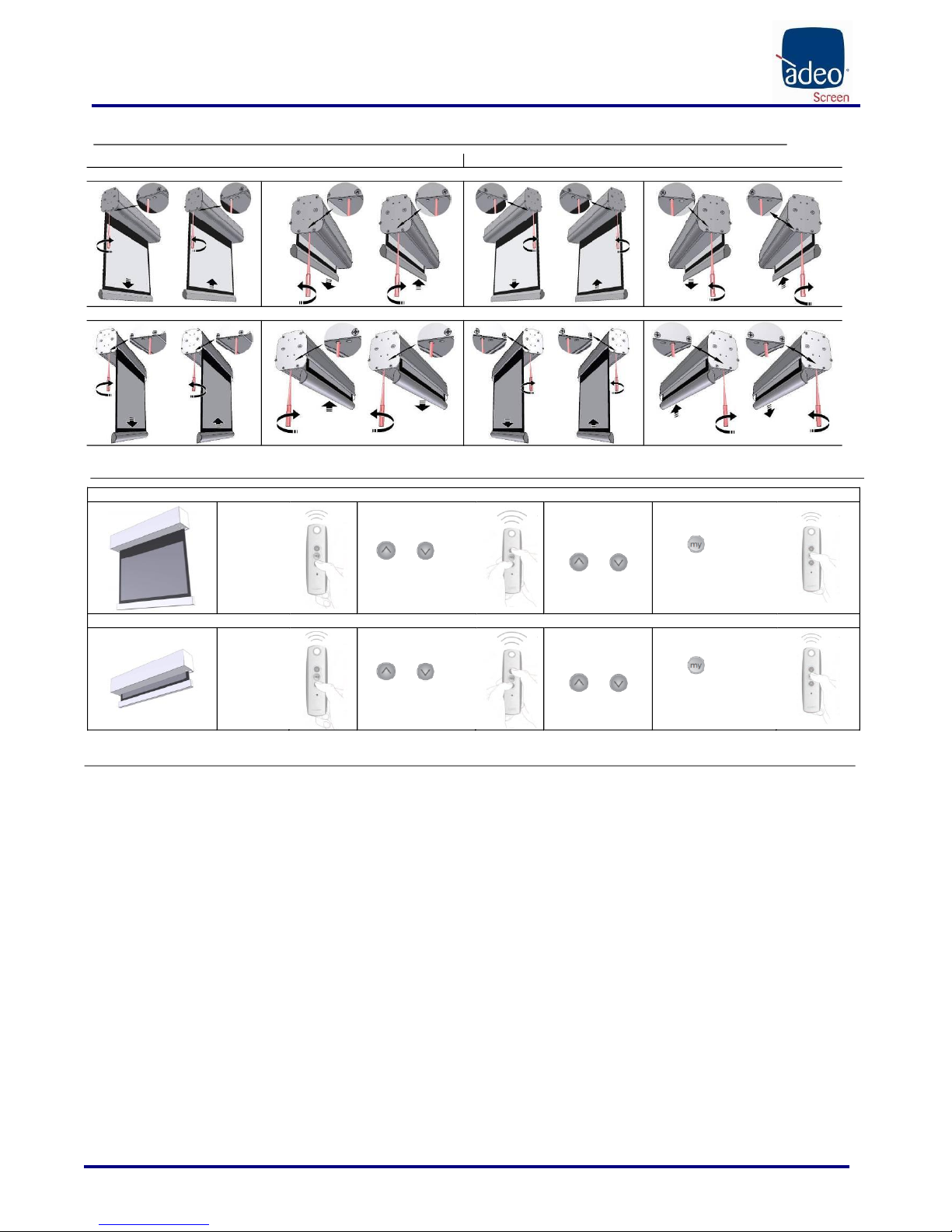
FRANCAIS –Manuel d’installation et d’utilisation de l’écran de projection
Made by Adeo Screen Sp. Z o.o. (Poland) Specifications are subject to change without notice. E&OE
Doc: PROFESSIONAL Installation Manual rev2 | 13.06.2017
Please verify that you are working with the latest revision of this document before specifying your screen.
Page 19
10 RÉGLAGE DES FINS DE COURSE NICE
A –Moteur à gauche
B –Moteur à droit (standard)
Déroulement par l’arrière - C
Déroulement par le devant - D
PROGRAMMATION DE MOTOR SOMFY RTS 230V 50Hz/120V 60Hz (procédure déjà effectuée en usine, ne doit pas être effectuée par un personnel non autorisé)
Down limit switch
1
Move the
screen surface
to down limit
switch.
2
Press both
and at the
same time until you will see
a brief up and down motion
of screen surface.
3
Move the screen with
buttons
and
to reach the desired
down limit position.
4
Press button until you
will see a brief up and donw
motion of screen surface to
memorize the new position
Up limit swicht
1.
Move the
screen surface
to up limit
switch.
2
Press both
and at the
same time until you will see
a brief up and down motion
of screen surface.
3
Move the screen with
buttons
and
to reach the desired up
limit position.
4
Press button until you
will see a brief up and donw
motion of screen surface to
memorize the new position
GARANTIE
1.LIMITES DE LA GARANTIE Le producteur garantit que les produits qu’il distribue sont exempts de tout défaut de fabrication, des matériaux et d’usinage,
et que les termes et les conditions ci-après restent entendus :
* Le produit est garanti pour une période de vingt-quatre (24) mois
à compter de la date de la facture d’achat ou du ticket de caisse de l’utilisateur final
2.CONDITIONS ET LIMITATIONS La présente garantie est soumise aux conditions et limitations suivantes.
La garantie est nulle et inapplicable si le produit a été utilisé ou manipulé sans respecter les instructions contenues dans le mode d'emploi, s’il a été endommagé suite à un abus ou à un usage impropre du
produit, en cas de dommages causés lors d’un accident ou de négligence pendant le transport, si le défaut du produit est dû à des réparations ou autres modifications effectuées par des personnes non
autorisées par le Service Clients.
Le produit doit être installé par des professionnels du secteur ou par un personnel techniquement préparé, en suivant les procédures d’installation et de manutention indiquées dans les instructions.
3.RETOURS DE MARCHANDISE Aucun produit restitué ne sera accepté sans autorisation écrite (RMA) de la part de notre Service Clients.
Les produits doivent être rendus avec l’emballage original ou autre emballage équivalent afin d’éviter tout endommagement pendant le transport. Les dommages dus à un emballage inapproprié pour le
transport ne sont pas pris en compte dans la garantie.
Le produit restitué doit être accompagné d’une description détaillée du défaut et d’une photocopie de la facture ou du reçu original d’achat.
Le reçu ou la facture doivent contenir de façon claire les données suivantes : modèle - numéro de série - date d’achat - nom et adresse de l'acheteur et du revendeur autorisé

DEUTSCH –Bedienungs- und Installationsanleitung: Motorleinwand
Made by Adeo Screen Sp. Z o.o. (Poland) Specifications are subject to change without notice. E&OE
Doc: PROFESSIONAL Installation Manual rev2 | 13.06.2017
Please verify that you are working with the latest revision of this document before specifying your screen.
Page 20
01 EINFÜHRUNG
Dieses Handbuch ist integraler Teil des Produkts, und dessen Lektüre und Verständnis sind von wesentlicher Bedeutung für die Sicherheit. Darin sind die Normen und
Verwendungsmodalitätenbeschrieben, die dem Kunden eine richtige undsichere Nutzung der Projektionswand ermöglichen. Das Handbuch muss stets beim Produkt verbleiben und ist
sorgfältig an einem geeigneten Ort aufzubewahren, um seine Unversehrtheit zu gewährleisten und allen berechtigten Personen zur Hinzuziehung zugänglich zu sein. Jeder Nutzer des
Produkts ist für den Schutz des Handbuchs verantwortlich. Außerdem ist er für die Überprüfungder Funktionstüchtigkeit der Projektionswand und für alle Reparaturen und den
Austausch von abgenützten Teilen, die Schädenverursachen könnten.
Die in diesem Handbuch enthaltenen Bilder dienen dazu, Funktionen, Eigenschaften und Verfahren im Detail zu zeigen. Trotzdem können sie sich je nach dargestelltem Modell
unterscheiden, wobei sich jedoch die Bedeutung des Bildes im Hinblick auf den beschreibenden Zweck nicht ändert
02 ALLGEMEINE SICHERHEITSVORSCHRIFTEN
ACHTUNG: Wichtige Sicherheitshinweise. Diese Hinweise sind unbedingt zu beachten, da eine unsachgemäße Installation schwere Verletzungen verursachen kann.
Lesen Sie die Anleitungen und Hinweise dieser Gebrauchsanleitung vor Verwendung des Produkts oder Durchführung jeglicher Art von Wartung und versichern Sie sich, dass
Sie sie verstanden haben. Installation des Bildschirms über Durchgangszone ist streng verboten.
- Überprüfen Sie vor und während der Verwendung, dass die Projektionswand keine gefährlichen Situationen erzeugt.
- Keines der Elemente oder Teile der Projektionswand beschädigen oder entfernen.
- Niemals Wartungsarbeiten an der Leinwand bei eingeschaltetem Motor vornehmen (sicherheitshalber das Stromkabel ausstecken).
- Während der Reinigung, der Wartung oder beim Austausch von Teilen immer das Gerät von der Stromversorgung trennen.
- Das Produkt darf unter keinen Umständen von Kindern benutzt werden. Kinder dürfen sich der Projektionswand unter keinen Umständen nähern, solange diese sich bewegt.
Jede Projektionswand ist durch eine Garantie gedeckt, deren Gültigkeit von der tatsächlichen Einhaltung der Anleitungen in diesem Handbuch abhängt.
ACHTUNG: Eine falsche Installation kann die Sicherheit der Anwender des Produkts beeinträchtigen. Der Hersteller lehnt jegliche Haftung für Personen- bzw. Sachschäden ab,
die auf unsachgemäße Benutzung, Montagefehler oder ungenügende Wartung zurückzuführen sind.
Der Hersteller haftet nicht für Probleme, die durch Installationsfehler verursacht werden.
Die Montage der Leinwand, die elektrischen Anschlüsse und die Überprüfungen bei Störungen der motorbetriebenen Wicklungen sind von einem hierzu befugten Händler oder
von Fachpersonal durchzuführen, das Kenntnis von den Gefahren hat, die von elektrischer Energie ausgehen. Das Anschlusskabel kann nicht ersetzt werden. Bei
Beschädigung des Kabels muss die gesamte Leinwand ausgetauscht werden. Eingriffe an den Endschaltern oder das Aufbrechen der angebrachten Siegel führen zu
Garantieverlust. Bei Rückfragen wenden Sie sich bitte an unser technisches Büro.
NACH DER MONTAGE DES BILDSCHIRMS AN DEN BÜGELN IST VOR DER VERWENDUNG SICHERZUSTELLEN, DASS DER BILDSCHIRM PERFEKT HORIZONTAL POSITIONIERT IST.
03 HINWEISE UND VORSICHTSMASSNAHMEN FÜR DEN GEBRAUCH UND INSTALLATION
Die Leinwände sind für die Benutzung in Innenräumen unter normalen Temperatur- (20 - 25 °C) und Feuchtigkeitsbedingungen vorgesehen.
Es ist absolut verboten die Projektionsleinwände vor Fenstern zu installieren oder sie als Verdunkelungsrollos zu verwenden. Sie dürfen weder direkter Sonnenbestrahlung ausgesetzt sein noch in der Nähe
von starken Lichtquellen, Wärmequellen (z. B. Öfen, Kamine oder Schornsteine) oder Klimaanlagen (Warmluft oder Kaltluft) installiert werden. Bei Nichteinhaltung dieser Verbote könnte die
Projektionsleinwand verformt oder permanent verzogen werden.
Der Einsatz der motorisierten Leinwand im Außenbereich erfordert besondere Vorsichtsmaßnahmen:
1- Das/Die Stromzufuhrkabel des Motors mittels für den Außenbereich geeigneter Kabelkanäle oder Kabelmäntel vor UV-Strahlung schützen.
2- An den Anschlussstellen mit den Verbindungs- oder Abzweigkästen wasserundurchlässige und feuchtigkeitsbeständige Kabeldurchführungen verwenden.
3- Nur Schalter mit Schutzart IP55 oder höher verwenden (der serienmäßig mitgelieferte Schalter ist nicht für den Außenbereich geeignet).
4- Bedecken und schützen Sie die Leinwand vor direktem Kontakt mit Wasser oder anderen Flüssigkeiten.
Da das Material, aus dem die Leinwand besteht (PVC), zur elektrostatischen Aufladung neigt, kann sich bei übermäßigem Staubanfall in der Umgebung durch die elektrostatische Anziehung dieser Staub auf
der Leinwand ablagern und zu einer Beeinträchtigung ihrer optischen Eigenschaften führen (siehe auch Reinigung der Leinwand).
Leinwände dürfen niemals in der Nähe von Hitzequellen oder nahe Klimageräten installiert werden, da dies das empfindliche Projektionstuch beschädigen kann.
Eine Rollbildwand soll bei Verwendung stets komplett ausgerollt und nach Verwendung wieder ganz eingefahren werden. Dieser Prozess, des vollständigen heraus- und wieder hineinfahrens wird hier als ein
“Zyklus “ bezeichnet.
Die motorisierte Rollbildwand ist zur Verwendung in jeweils einem Zyklus konzipiert. Dies bedeutet, dass zwischen den Zyklen gewöhnlich eine beträchtliche Menge an Zeit vergeht. Das Verwenden der
Projektionswand ist nicht zum ständigen Öffnen und Schließen in kurzen Intervallen vorgesehen.
Die in der Projektionswand verwendeten Motoren sind mit einem thermischen Überlastschutz ausgestattet. Dieser verhindert ein Überhitzen und Beschädigung des Motors. Die Aktivierung der Thermo-
Schutzschaltung geschieht nach einer gewissen Anzahl an Zyklen. Die Anzahl der Zyklen variiertabhängig von der Art des Motors und Art und Größe der Projektionswand (gewöhnlich zwischen 3 bis 6 Zyklen).
Bitte beachten Sie, dass die Abwärme des Motors auf die Welle übertragen wird und somit auf das Gewebe, welches auf der Welle gewickelt ist. Das Erhitzen des Gewebes kann in bleibenden Verformungen
oder Dehnung bzw. Verzerrung resultierenden.
Um Beschriebenes zu vermeiden, ist dringlich davon abzuraten, die Projektionswand mit mehr als 3 vollständigen, aufeinanderfolgenden Zyklen (aufwärts-abwärts) zu verwenden.
Nach 3 aufeinanderfolgenden oder nahe beieinander liegenden Zyklen müssen mindestens 40 Minuten mit ausgefahrener Projektionsfläche (ausgerolltes Gewebe) abgewartet werden, um vor dem erneuten
Verwenden den Motor und entsprechende Bauteile abkühlen zu lassen.
ACHTUNG: Die Leinwand nicht gewaltsam von Hand herausziehen, da dadurch der Motor beschädigt oder der Bügelkasten abgerissen werden könnte.
Erlauben Sie Kindern nicht, mit den fest angebrachten Steuervorrichtungen zu spielen.
Beobachten Sie die Leinwand und halten Sie Personen davon fern, bis die Projektionswand völlig geschlossen ist.
Es ist verboten, die Bewegung der Leinwand zu blockieren, zu verhindern oder zu erzwingen, sich an der Leinwand oder an der unteren Schiene festzuhalten oder daran zu schaukeln, Gegenstände an der
Leinwand oder an der unteren Schiene anzubringen oder die Struktur der Leinwand zu ändern, da dies zu Schäden am Aufwickelsystem und somit zu Personen- und Sachschäden führen kann.
Es ist absolut verboten die Projektionsleinwände vor Fenstern zu installieren oder sie als Verdunkelungsrollos zu verwenden.
Es ist absolut verboten die Projektionsleinwände in der Nähe von Wärmequellen (z. B. Öfen, Kamine oder Schornsteine) oder Klimaanlagen (Warmluft oder Kaltluft) zu installieren.
Positionieren sie Leinwände perfekt waagrecht.
PRODUKTENTSORGUNG
Produkt gilt, gilt auch am Ende der Lebensdauer für seine Entsorgung: sie ist von Fachpersonal vorzunehmen.
Dieses Produkt besteht aus verschiedenen Materialien: einige können wieder verwertet werden, andere sind zu entsorgen. Holen Sie Informationen über das in Ihrem
Land geltende Recycling-und Entsorgungssystem für diese Produktkategorie ein.
Wie Sie aus dem Symbol hier links ersehen können, ist es verboten, das Produkt in den Hausmüll zu geben. Befolgen Sie also die Vorgaben zur Mülltrennung nach den
in Ihrem Land geltenden Vorschriften oder geben Sie das Produkt beim Neukauf eines gleichwertigen Artikels an den Händler zurück.
ACHTUNG: die örtlichen Gesetze können schwere Strafen bei missbräuchlicher Entsorgung dieses Produkts vorsehen
This manual suits for next models
7
Table of contents
Languages:
Other ADEO SCREEN Projector Accessories manuals


