Adeunis RF ARF53 User manual

No part of this document may be reproduced or transmitted (in electronic or
paper version, photocopy) without Adeunis RF consent.
This document is subject to change without notice.
All trademarks mentioned in this guide are the property of their respective
owner.
ADEUNIS RF
283, rue Louis Néel
38920 Crolles
France
Phone +33 (0)4 76 92 07 77
Fax +33 (0)4 76 08 97 46
Ref. 08-07-V6-lmn

A
RF53
User Guide
Ref. 08-07-V6-lmn p 1
Table of Contents
Table of Contents..............................................................................1
About this document.........................................................................2
Compliance to FCC US/CAN ..............................................................3
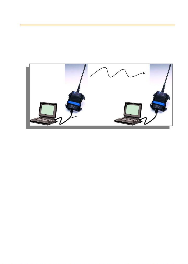
Overview...........................................................................................4
Product Power supply .......................................................................4
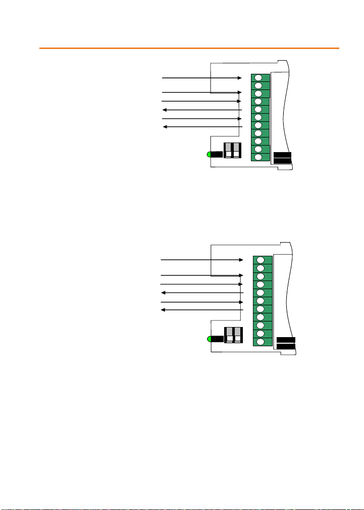
Serial link wiring...............................................................................5
MODEM / DTE RS232.........................................................................5
DCE RS232........................................................................................6
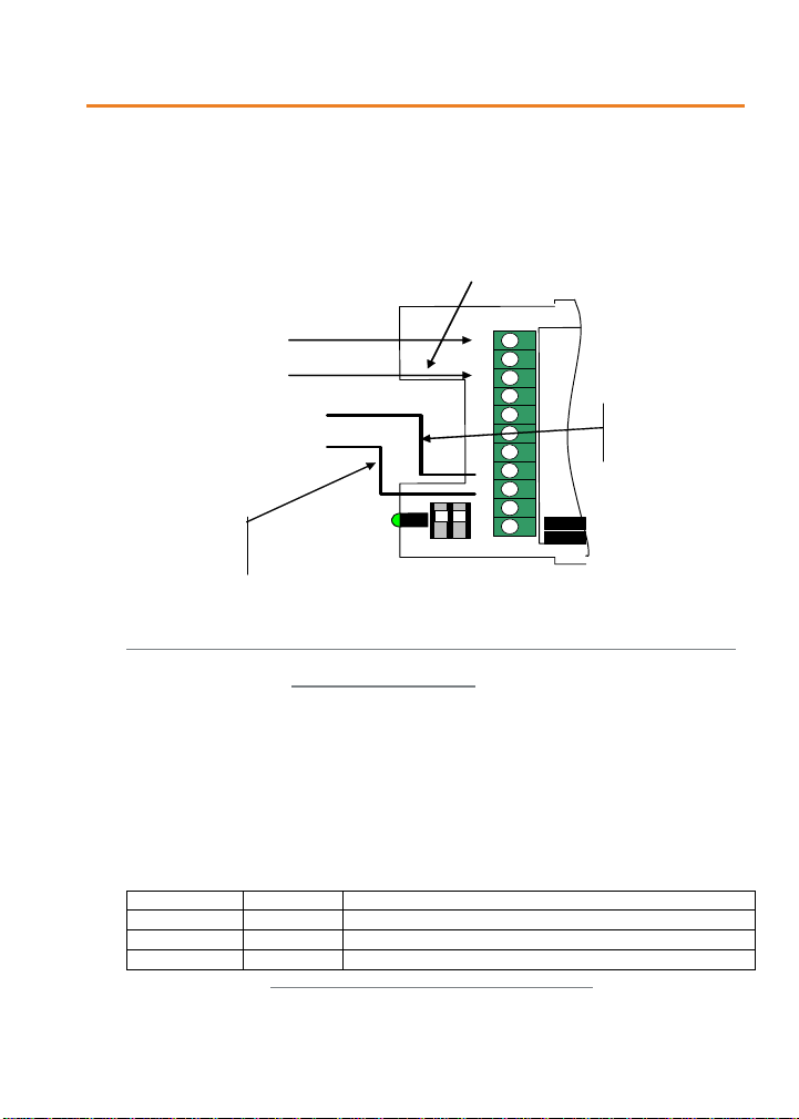
RS485 wiring .....................................................................................7
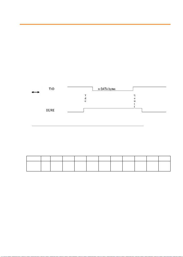
Radio communication .......................................................................9
Radio channels & Sub-bands ............................................................10
Channel selection.............................................................................11
Air radio rate selection .....................................................................11
Channel rejection.............................................................................11
RSSI reading ...................................................................................12
Transceiver operating mode ...........................................................12
Command mode ..............................................................................13
Transceiver state machine................................................................14
AT Commands .................................................................................15
Description ......................................................................................15
Set of commands.............................................................................15
Register description .........................................................................17
Specifications..................................................................................21
Glossary ..........................................................................................23
ANNEX : Firmware updates.............................................................23
TOP

A
RF53
User Guide
Ref. 08-07-V6-lmn p 2
About this document
This guide describes the A
RF53
devices, their options and accessories.
TOP

A
RF53
User Guide
Ref. 08-07-V6-lmn p 3
Compliance to FCC US/CAN
This equipment has been tested and found to comply with the limits
for a Class B digital device, pursuant to Part 15 of the FCC Rules.
These limits are designed to provide reasonable protection against
harmful interference in a residential installation. This equipment
generates, uses and can radiate radio frequency energy and, if not
installed and used in accordance with the instructions, may cause
harmful interference to radio communications.
However, there is no guarantee that interference will not occur in a
particular installation. If this equipment does cause harmful
interference to radio or television reception, which can be
determined by turning the equipment off and on, the user is
encouraged to try to correct the interference by one or more of the
following measures :
-- Reorient or relocate the receiving antenna.
-- Increase the separation between the equipment and receiver.
-- Connect the equipment into an outlet on a circuit different from
that to which the receiver is connected.
-- Consult the dealer or an experienced radio/TV technician for help.
CHANGES OR MODIFICATIONS NOT EXPRESSLY APPROVED BY
ADEUNIS RF COULD VOID THE USER’S AUTHORITY TO OPERATE
THE EQUIPMENT.
RF Exposure Warning: During operation, the user may keep a
minimum separation distance of 20 cm with the RF devices.
TOP

A
RF53
User Guide
Ref. 08-07-V6-lmn p 4
Overview
The modem converts data from a serial link into a radio frame to be
sent to a similar piece of equipment.
The operating parameters of these modems (serial link, radio
management…) can be updated through commands on the serial
link.
The products are available either in card version to be integrated in
an assembly or as an IP65 chip. In the IP65 case, the products are
fixed with the fixing lugs onto the top (antenna) and bottom (stuffing
box) of the casing (4 screws not provided).
Product Power supply
To perform wiring of these products, the bottom part of the housing
(part with stuffing box) has to be opened by unscrewing the two
stainless steel screws on each side.
RS232 serial lin
k
Radio transmission
TOP

A
RF53
User Guide
Ref. 08-07-V6-lmn p 5
Retirer les vis de la partie
avec presse étoupe
Remove these screws
The ARF53 range products are supplied from a DC voltage source. This
voltage source must be 4,5V minimum and must not exceed 36 Vdc. Green
LED is ON when powered.
EASY CHECK
Green LED is ON when modem is
powered.
Serial link wiring
MODEM / DTE RS232
This is for example the case of a modem connected to a PC. RTS and
CTS are required only if flow control is used.
+DC Supply.
+-RX TX
ON
RTS CTS TX+ TX- RX+ RX-
ON
1 2
TOP

A
RF53
User Guide
Ref. 08-07-V6-lmn p 6
N° / SUB-D 9 NOM
+ Vcc
5 GND
2 RXD
3 TXD
+
-
RX
TX
RTS
CTS
TX+
TX-
RX+
RX-
ON
1 2
7 RTS
5
8 CTS
DCE RS232
This is for example the case of a modem connected to a measuring
device. RTS and CTS are required only if flow control is used.
N° / SUB-D 9 NOM
+ Vcc
5 GND
3 RXD
2 TXD
+
-
RX
T
X
INHIB
RTS
CTS
T
X+
T
X-
RX+
RX-
ON
1 2
8 RTS
7 CTS
EASY CHECK
Serial link activity will make the green LED flashing, whatever the
selected data rate is right or wrong.
TOP

A
RF53
User Guide
Ref. 08-07-V6-lmn p 7
RS485 wiring
The RS485 bus wiring needs only two wires (TX+ is connected to RX+ and
TX- is connected to RX- on the PCB)
BUS RS485 NAME
+ Vcc
GND
A
TX+/RX+
B TX-
/
RX-
+
-
RX
TX
INHIB
RTS
CTS
TX+
TX-
RX+
RX-
Connect only TX-
or RX- (note 1)
Connect only TX+
or RX+ (note 1)
Note 1:
¾TX- is connected to RX- on the PCB
¾TX+ is connected to RX+ on the PCB
ON
1 2
Figure 1: RS485 wiring
In order to activate the RS485 management the SW1.1 switch MUST be ON
and the S215 value MUST be 1 (see the following table).
WARNING
the SW1.1 switch is read only at the power-up. Changing the SW1.1 switch
when the modem is already running will not be taken in account.
Table 1: R485/232 configuration settings
S215 values SW1.1 Note
1 ON RS485 control lines management
1 OFF RS232 configuration
0 ignoré RS232 configuration
TOP

A
RF53
User Guide
Ref. 08-07-V6-lmn p 8
By default the DE and RE lines are asserted LOW, allowing receiving
character from the RS485 differential bus. The DE and RE lines are asserted
HIGH only when one or several characters have to be transmitted over the
RS485 differential bus: when a radio frame is demodulated, the lines are
asserted HIGH and then the data extracted from the radio frame are sent to
the module TXD line and therefore to the RS485 differential bus. When the
last character has been transmitted over the RS485 differential bus, the lines
are asserted LOW.
Figure 2 : DE/RE timing when data are sent over the serial link
Threshold: minimum = 1 µs
Tde: set according to the S219 register value (see table hereafter)
S219 0 1 2 3 4 5 10 20 40 60 80
Tde
min 15
µs 35
µs 65
µs 135
µs 150
µs 190
µs 330
µs 600
µs 1,1
ms 1,7
ms 2,3
ms
In command mode, a reply is sent back (on the TXD line) according to the
following DE/RE timing:
The RS485 link needs to be adapted (each side). The modem includes a
100Ωtermination resistor:
SW1.2 = ON, the resistor is connected between A and B (respectively RX+
and RX-)
SW1.2 = OFF, the resistor is not connected between A and B.
If the modem is ending the RS485 bus, SW1.1 must be ON.
TOP

A
RF53
User Guide
Ref. 08-07-V6-lmn p 9
100 Ω
Rt
SW1.2
B
A
B’ / Z
A’ / Y
R
T
B / RX-
A / RX+
Z / TX-
Y / TX+
R
T
MODEM
Network termination 485
RS485 Network
EASY CHECK
Serial link activity will make the green LED flashing, whatever the selected
data rate is right or wrong.
Radio communication
This modem has 50 channels over the 902-928 MHz Band used through FHSS
transmission. Hopping is possible over the whole range but also selectable
over up or down sub-bands. These modes can be selected using AT
commands.
Wide Band transmission:
•3 modes, FHSS over 25 or 50 channels
•57,6 kbit/s radio rate
•channel spacing: 500 kHz
•Sensitivity : - 108 dBm
•Adjacent channel rejection: see chapter. Erreur ! Source du
renvoi introuvable.
Narrow Band transmission:
•3 modes, FHSS over 25 or 50 channels
•10 kbit/s radio rate
•channel spacing: 500 kHz
•Sensitivity : - 112 dBm
•Adjacent channel rejection: see chapter. Erreur ! Source du
renvoi introuvable.
This module is designed to operate according to FCC Part 15.247.
TOP

A
RF53
User Guide
Ref. 08-07-V6-lmn p 10
NOTE
when delivered this modem is set up in Narrow Band to optimize the range.
NOTE 1
The RF out power could be adjusted using AT commands (see register S231).
Radio channels & Sub-bands
The 50 channels are available according to the following table:
Channel
S200 Frequency
(MHz) Channel
S200 Frequency
(MHz)
Low Sub Band High Sub Band
0 902.75 25 915.25
1 903.25 26 915.75
2 903.75 27 916.25
3 904.25 28 916.75
4 904.75 29 917.25
5 905.25 30 917.75
6 905.75 31 918.25
7 906.25 32 918.75
8 906.75 33 919.25
9 907.25 34 919.75
10 907.75 35 920.25
11 908.25 36 920.75
12 908.75 37 921.25
13 909.25 38 921.75
14 909.75 39 922.25
15 910.25 40 922.75
16 910.75 41 923.25
17 911.25 42 923.75
18 911.75 43 924.25
19 912.25 44 924.75
20 912.75 45 925.25
21 913.25 46 925.75
22 913.75 47 926.25
23 914.25 48 926.75
24 914.75 49 927.25
Figure 3:Channels & Sub bands
TOP

A
RF53
User Guide
Ref. 08-07-V6-lmn p 11
Channel selection
S220 = 2: Frequency hopping over the whole 50 channels
S220 = 3: Frequency hopping over the lower Sub Band
S220 = 4: Frequency hopping over the higher Sub Band
ATS200? = Viewing the hopping table (Channel numbers)
Air radio rate selection
S202 = 0: 10 kbps Narrowband
S202 = 1: 57.6 kbps Wideband (Default)
Channel rejection
The graph below shows the typical channels rejection in WideBand (WB) and
NarrowBand (NB) modes.
10
20
30
40
50
60
70
80
-2000 -1750 -1500 -1250 -1000 -750 -500 -250 0 250 500 750 1000 1250 1500 1750 2000
frequency step / Fchannel (kHz)
rejection (dB)
WB
NB
NOTES
Particular attention is required for product installation. In the case where
several links must works in the same area (independently of the channel
positions), the minimum distance between 2 products belonging to different
radio links is 3 meters. Even with this precaution (depending of the product
environment), channel rejection could be reduced.
TOP

A
RF53
User Guide
Ref. 08-07-V6-lmn p 12
RSSI reading
The RSSI (Received Strength Signal Indicator) gives an indication for the
received power level on the first channel of the hopping table.
It could be accessed with ATS230?<cr> command.
Power level
NOTE
The RSSI level is only an indication. Use this level with care due to the
dispersion between components.
The schema above could be modified from one to another product. The
operating temperature could also have an impact on these dispersions.
The RSSI level could also indicate the potential presence of any jammer in
the used channel.
The RSSI is a necessary but not sufficient condition to get a correct reception.
Transceiver operating mode
Two operating modes are available:
•Command mode (usage of AT commands)
•Transceiver or normal mode (serial data are transmitted on radio
link)
At power up the transceiver is in transceiver mode: it is able to send / receive
data to / from the radio link according to its current parameter configuration.
TOP

A
RF53
User Guide
Ref. 08-07-V6-lmn p 13
Command mode
The command mode is used to read and update the modem configuration
registers using AT command.
NOTE
The AT command can be locked using ATPWD command.
In command mode, the radio is inhibited (reception and transmission),
excepted when using test command.
Entering command mode: issues on the serial link a +++ sequence. The
sequence of 3 consecutive + characters is accepted only if no character have
been seen before and after the +++ sequence. Register (S214) defines the
silence duration.
TIPS 1
if you are using a terminal (such as Hyperterm), you have to send the +++
sequence using a text file (first create a text file containing only the +++
characters, and then use in Hyperterm the command “Send text file” in the
“Transfer menu”)
TIPS 2
Exiting command mode (return back in transceiver mode): send the serial
command
ATO <cr>
EASY CHECK
When receiving a right command, modem will answer:
‘O’<cr> (ASCII character 0x4F) for accepted command (or OK command)
‘E’<cr> for error
TOP

A
RF53
User Guide
Ref. 08-07-V6-lmn p 14
Specific string when specified
Transceiver mode
The transceiver mode used a secured addressed protocol.
The communication is always half-duplex. The radio transmission is processed
prior to the radio reception. When the transceiver is sending a radio packet, it
is not able to decode any incoming radio packet.
If no data are sent on the serial link, the modem is waiting for radio
reception. Each radio packet sent by another modem is received and the
validated data extracted from the radio packet are sent on the serial link.
All the data received on the serial link are encapsulated in a radio packet.
In transmission mode, data received on the serial link are sent on the radio
link with the following format:
<Preamble><synchro><packet header> DATA <CRC><postambule>.
Preamble, synchronisation and postambule are used for the radio reception.
The packet header contains the following fields : packet length, number of
retries and packet number, target address.
The CRC follows the data and check the integrity of the radio packet.
The Target Address field is set up with S256 register. The Target Address
value 0000 is a broadcast address.
In reception mode: The <Target Address> field of the radio packet is
checked (if different of 0000) with the reception address (S252).
If the radio packet address matches the transceiver reception address (S252),
DATA (and only DATA) are transmitted on the serial link
Otherwise received data are silently discarded.
Transceiver state machine
When operating in transceiver mode the 'RF transmission' state machine is:
Idle state of the transceiver: by default the transceiver is waiting for
incoming data on the RS232 link and for incoming radio packet on the radio
link.
Processing incoming RS232 data: the incoming RS232 data are internally
buffered. The buffered data are encapsulated in a radio packet and
transmitted.
TOP

A
RF53
User Guide
Ref. 08-07-V6-lmn p 15
Processing incoming radio frame: the valid data are extracted from the
incoming radio packet and internally buffered. The buffered data are sent on
the fly to the RS232 module output.
AT Commands
Description
AT commands are interpreted only when the transceiver is in Command
mode. Command : are used to read and update the modem parameters
A command starts with the 2 ASCII ‘AT’ characters. ‘AT’ means ‘Attention’
follow with one or several characters or other data.
Each command is ended with <cr> (carriage return).
In the same command, the time between 2 characters must be less than 10s.
EASY CHECK:
When receiving a right command, modem will answer:
‘O’<cr> (ASCII character 0x4F) for accepted command (or OK command)
‘E’<cr> for error
Specific string when specified
Set of commands
Commands Description
Operating mode selection
ATO Return back to transceiver mode.
<silence>+++<silence> Command mode activation. The +++ sequence must be
preceded and followed by a calibrated silence (no other
character)
Registers management
TOP

A
RF53
User Guide
Ref. 08-07-V6-lmn p 16
ATSn? Displays the Sn register content where n represents the
register number.
The response has the following format:
Sn=y<cr><lf>
ATSn=m Sets the Sn register value with ‘m’. n represents the register
number..
AT&W Saves the new register configuration in EEPROM. Each time
you switch on the modem, the EEPROM configuration will be
loaded in the modem registers.
AT/S Displays all register values. The response has the following
format:
Sxxx=y<cr><lf> for each register.
AT/V Software version display. The response has the following
format:
Adeunis RF Versatile Modem II 915 MHz 500mW
Vxx.yy<cr><lf>
ATR Restore the register default values
Be careful: When restoring USB DC supplied modem regs,
S231 - RF power will become “3” which is incompatible with
USB power supply.
ATPWD=m m = pin code (re
g
ister S205) : unlock all AT commands.
m = 0000 : set registers to default value and unlock all AT
commands.
Test modes
ATT1 Pure Carrier (data=0) transmission using current channel.
The output of this mode is achieved by reception of any
character on the serial link.
ATT2 Pure Carrier (data=1) transmission using current channel.
The output of this mode is achieved by reception of any
character on the serial link.
ATT3-ATT6 Modulation using current channel. The output of this mode
is achieved by reception of any character on the serial link.
ATT3: 0.9 KHz modulation
ATT4: 3.6 KHz modulation
ATT5: 14.4 KHz modulation (Wide Band channel
only)
ATT6: 28.8 KHz modulation (Wide Band channel
only)
TOP

A
RF53
User Guide
Ref. 08-07-V6-lmn p 17
Register description
The register value could be updated using the ATSn=m<cr> command and
displayed using ATSn?<cr> command.
At power-up, the previous transceiver configuration is restored from E2PROM
(non volatile) to RAM. The registers are located in RAM registers, any
modification is performed on RAM registers: To save current register
configurations, it is necessary to use the AT&W<cr> command. If not, the
updated parameters are lost in case of power shortage.
The registers are shared in 2 types: read only (R) or read/write (R/W)
It is mandatory that the Master modem and the Slave modem have exactly
the same registers configuration in term of : hopping table (S200), start
channel (S201), channel type (S202), serial parameters (S210, S211, S212,
S213), handshake (S216), protocol (S220) and packet retries (S221).
It is recommended to have the same RF OUT level (S231).
Type Regi
ster Function Description Default
value Note
Radio management
R/W S200 Hopping table Hopping table
Default
table 4
R/W S201 Start channel Start channel number for hopping table 0
R/W S202 Channel type Channel type configuration
0 : Narrow band (10 kbps)
1 : Wide band (57.6 kbps)
1 2
When leaving factory, this modem is set up in Narrow Band to optimize the range
R S230 RSSI level Displays the reception level of the latest
received message.
Response: S230=-xxx dBm<cr><lf>
with xxx decimal value
The RSSI values range from –115 up to
–60 dBm.
None
TOP

A
RF53
User Guide
Ref. 08-07-V6-lmn p 18
Type Regi
ster Function Description Default
value Note
R/W S231 RF OUT level Adjusts the RF out level
0 => 20 dBm (100 mW)
1 => 23 dBm (200 mW)
2 => 24,5 dBm (<450 mA for USB
power supply)
3 => 27 dBm (500 mW – Not for USB
power supply)
3
Serial link
R/W S210 Baudrate Serial link rate in bits/s
‘1’: 1 200
‘2’: 2 400
‘3’: 4 800
‘4’: 9 600
‘5’: 19 200
‘6’: 38 400
‘7’: 57 600
4 1,2,
3
R/W S211 Data length ‘7’ : 7 bits
‘8’ : 8 bits
8 2,3
R/W S212 Parity ‘1’ : none
‘2’ : even
‘3’ : odd
1 2,3
R/W S213 Stop bits ‘1 ‘ : 1 stop bit
‘2 ‘ : 2 stop bits
1 2,3
R/W S214 Command
timeout Time out duration for detecting the
+++ pattern, unit 10ms. From 1(10ms)
up to 100 (1s).
8 1
R/W S215 Interface type ‘0’ : RS232 only
‘1’ : RS232 or RS485 (managed DE/RE
lines) (RS485 if pin 6 tied to ground)
1
R/W S216 Handshake ‘0’ : hardware RTS mandatory if
packet retries register S221 =1 or
2.
‘2’ : none
2 2
TOP
This manual suits for next models
4
Table of contents
Other Adeunis RF Modem manuals