ADITIVA 3D ENDER 3 CONVEYOR 90 KIT User manual


Ender 3 Conveyor 90 Belt Kit assembly manual P a g e 2 | 26
www.belt3dprinterkit.com
Content
Chapter 1 Intro 3
Step 1.1 What is included in this kit? 3
Step 1.2 Needed tools 3
Chapter 2 Disassembling ENDER 3 3
Step 2.1 Removing screen 3
Step 2.2 Y axis and heatbed assembly 4
Step 2.3 Remove back endcaps 5
Chapter 3 Preparing frame 6
Step 3.1 Installing bottom plates 6
Chapter 4 Installing Belt and Heatbed system 9
Step 4.1 Preparing rollers 9
Step 4.2 Installing Rollers and Belt 10
Step 4.3 Installing Heatbed 14
Chapter 5 Finishing installation 16
Step 5.1 Screen installation 16
Step 5.2 Face plate mounting 17
Chapter 6 Electronics and firmware 17
Step 6.1 Electronics 17
Step 6.2 Firmware 18
Chapter 7 Calibrating bed and Z endstop 18
Step 7.1 Calibration 18
Ender 3 Conveyor 90 Belt Kit assembly manual P a g e 3 | 26
www.belt3dprinterkit.com
Chapter 1 Intro
Step 1.1 What is included in this kit?
In this kit you will find all the necessary parts for converting your regular Ender 3/PRO/V2 3d
printer models into a sequential Belt 3d printer. Parts lists are indicated on each step for better
understanding and guidance.
Step 1.2 Needed tools
In order to fully install this kit, you will need the next tools:
Set of Allen keys
Adjustable wrench or wrench kit
Measuring tape
Vernier caliper
Metal ruler (for alignment)
Arduino Uno and set of DuPont wires (for firmware flashing on older board version)
Chapter 2 Disassembling ENDER 3
In order to get ready to install this kit, you have to disassembly various segments of the original
3d printer, this part will guide you through entire process of preparation and getting ready to
install new parts.
In this part of the process, various electrical components will be temporarily disconnected for
practical purposes, you have to install them later though.
*Please be aware some original parts will be discarded and won’t be installed.
Figure 1. Assembled Ender 3
Step 2.1 Removing screen
Ender 3 Conveyor 90 Belt Kit assembly manual P a g e 4 | 26
www.belt3dprinterkit.com
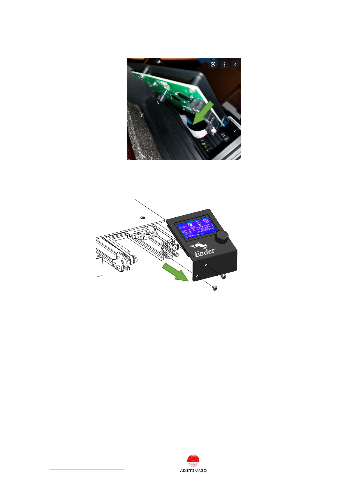
Remove cable from the back of the screen, please be aware of the connector position,
since it will be connected later.
Figure 2 disconnecting screen
Using an Allen key, remove 2 x m5 screws that holds screen in place.
Save both, screen assembly and screws for later use.
Figure 3 Removing screen
Step 2.2 Y axis and heatbed assembly
Using an Allen key, remove 2 x m5 screws that holds Y axis system with heatbed
assembly.
Save Y axis and heatbed assembly for later use, discard 2 x m5 screws.


Ender 3 Conveyor 90 Belt Kit assembly manual P a g e 7 | 26
www.belt3dprinterkit.com
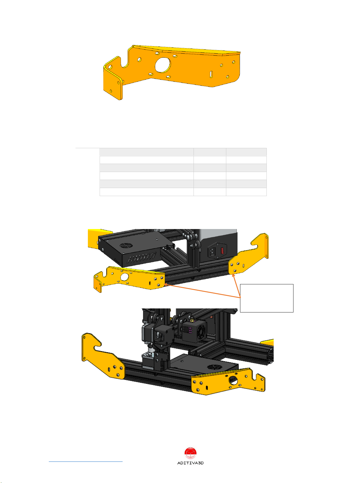
Figure 9: P4 C90 FRONT RIGHT BRACKET
Next items from the KIT:
ITEM
ITEM DESCRIPTION
Quantity
Type
1
P1 C90 BACK LEFT BRACKET
1
Kit
2
P2 C90 BACK RIGHT BRACKET
1
Kit
3
P3 C90 FRONT LEFT BRACKET
1
Kit
4
P4 C90 FRONT RIGHT BRACKET
1
Kit
5
M4 x 8 mm Screw
12
Kit
6
M4 T-Slot nut
12
Kit
Install 4 plates as shown in the next picture, M4 x 8 mm screws and M4 T-slot nuts will
be used, left and right sides must be assembled:
Figure 10 Installing bottom plates on each corner of bottom frame
3 M4x8 SCREW +
3 M4 SLOT NUT


Ender 3 Conveyor 90 Belt Kit assembly manual P a g e 9 | 26
www.belt3dprinterkit.com
Chapter 4 Installing Belt and Heatbed system
Figure 12 Belt system Assembly
Step 4.1 Preparing rollers
Next items from the KIT will be used:
ITEM
ITEM DESCRIPTION
Quantity
Type
1
Roller BODY 40 mm
2
Kit
2
12 mm ROD
2
Kit
3
Roller Cap 46mm
4
Kit
4
M4x8mm Black Headless screw
8
Kit
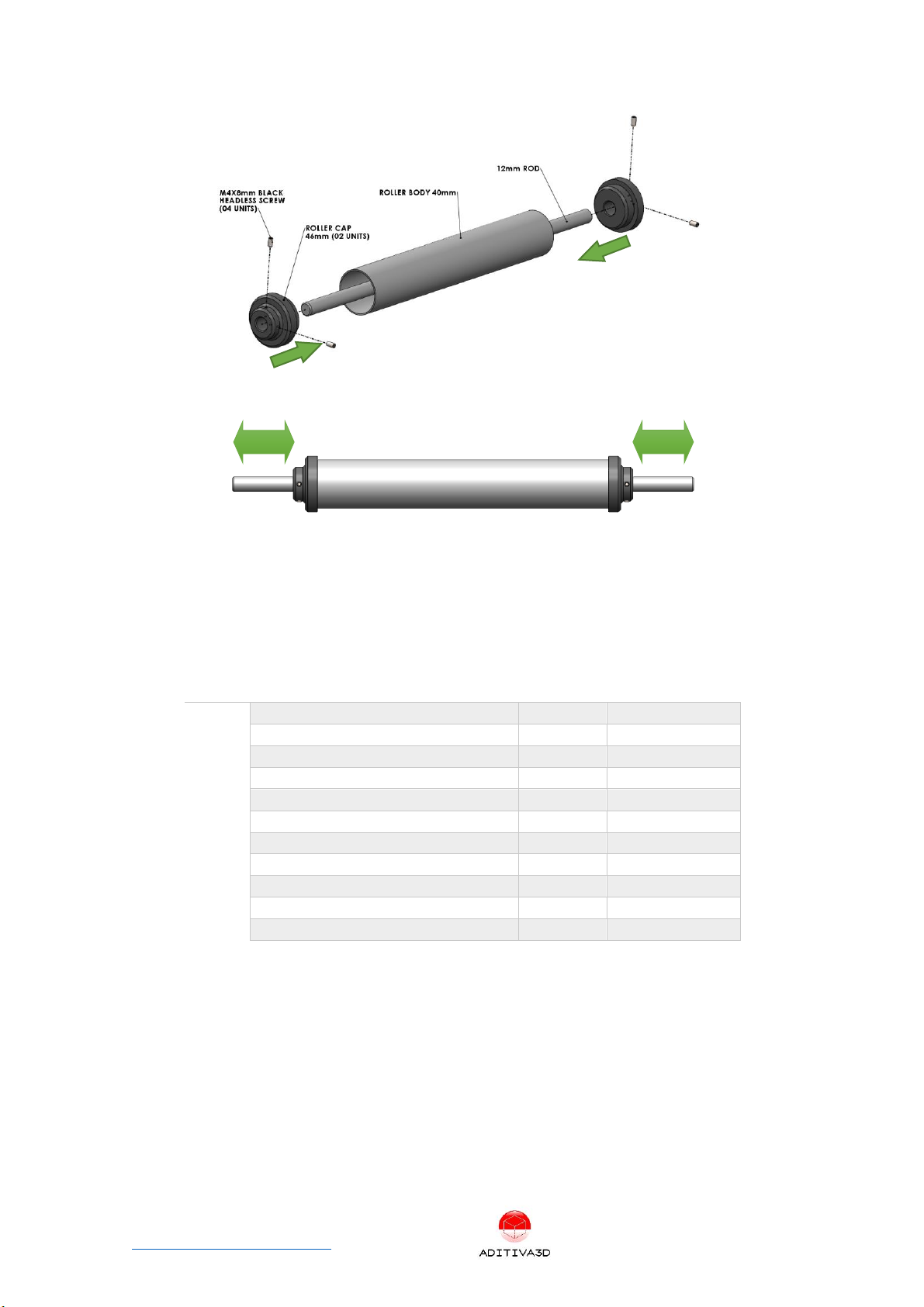
Using all the mentioned parts, proceed to assemble them in the next order, first place
12mm ROD inside Rolle BODY 40mm, then insert Roller CAP 46mm on each end, making
sure it all fits very tight, keep in mind that 12mm ROD have to be centered with the
roller body. Finally using an allen key, proceed to secure both ROLLE CAP 46mm with
the M4x8mm BLACK HEADLESS SCREWS (02 on each side):
*Note: You have to repeat this process in order to get 2 rollers assembly.
Ender 3 Conveyor 90 Belt Kit assembly manual P a g e 10 | 26
www.belt3dprinterkit.com
Figure 13 Roller assembly components
Figure 14 Rod is centered with roller body
Step 4.2 Installing Rollers and Belt
Next items from the KIT will be used:
ITEM
ITEM DESCRIPTION
Quantity
Type
1
Roller Assembly
2
Kit
2
FLANGE BEARING 12mm
2
Kit
3
BLOCK BEARING 12mm
2
Kit
4
M6x18mm SCREW
4
Kit
5
M6x30mm SCREW
4
Kit
6
M6 NYLOCK NUT
8
Kit
7
BELT
1
Kit
8
Timing Pulley 60T, Bore 12mm GT2
1
Kit
9
GT2 Timing belt Closed Loop
1
Kit
10
Y ORIGINAL MOTOR with its PULLEY
1
ORIGINAL PART
11
M3X6 SCREW
2
ORIGINAL PART
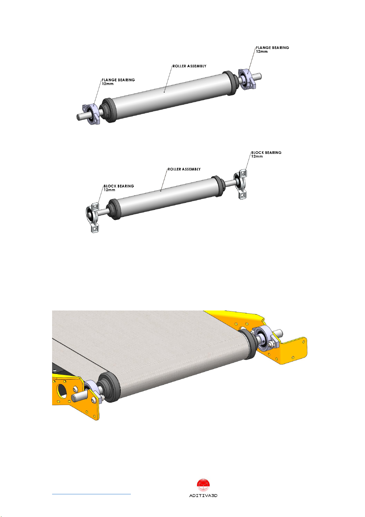
Insert Flange Bearing 12mm on both sides of one of the Roller:
50 mm
50 mm
Ender 3 Conveyor 90 Belt Kit assembly manual P a g e 11 | 26
www.belt3dprinterkit.com
Insert Block Bearing 12mm on both sides of the other Roller:
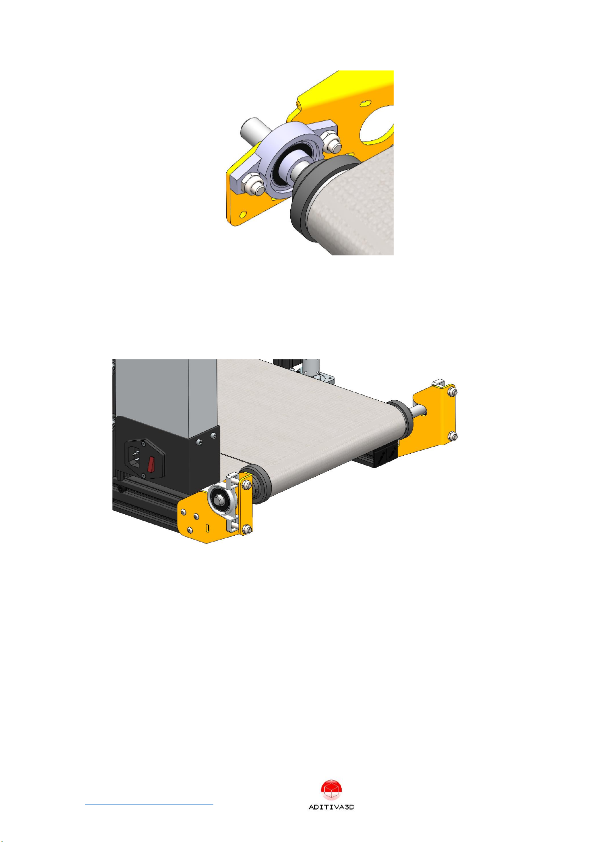
FRONT ROLLER MOUNT: Take the ROLLER with FLANGE BEARINGS on it, install it with
M6x18 SCREWS and M6 NYLOCK NUTS, please be aware in this step belt have to be
inserted as shown in the next picture. Secure both FLANGE BEARINGS by adjusting its
screws to hold it in place.
ROLLER HAS TO BE CENTERED!
At this point, no alignment is required, since it is mounted into round exact holes on the
side plates:
Figure 15 Front roller mount
Ender 3 Conveyor 90 Belt Kit assembly manual P a g e 12 | 26
www.belt3dprinterkit.com
REAR ROLLER MOUNT: Take the ROLLER with BLOCK BEARINGS on it, install it with
M6x30 SCREWS and M6 NYLOCK NUTS, please be aware in this step belt have to be
inserted as shown in the next picture, DO NOT ADJUST SCREWS YET, JUST INSTALL
SCREWS ON BOTH SIDES:
ROLLER HAS TO BE CENTERED!
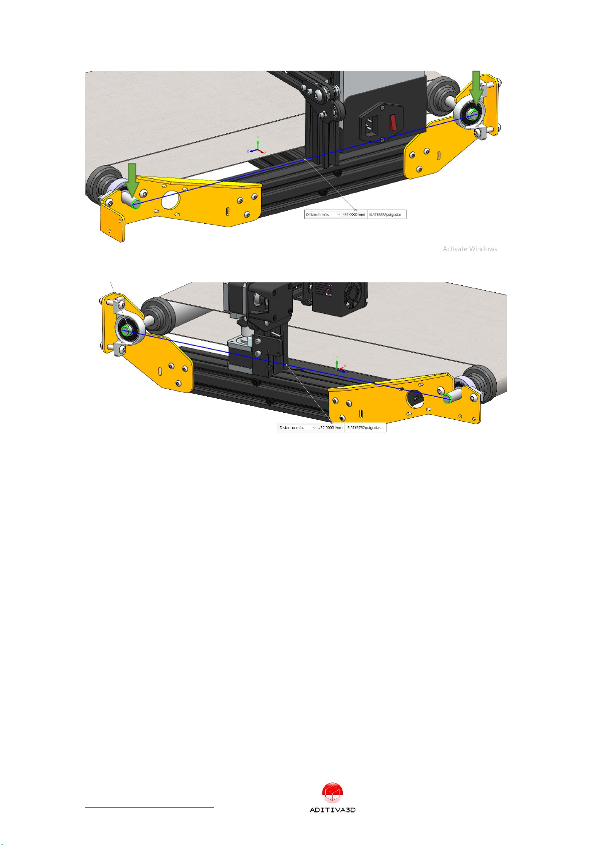
Belt tensioning: Using a measure tape, compare both ends of ROLLER SHAFTS (RODS),
on both sides, adjust Screws until measure is the same on both sides, approximately
dimension is about 480 to 485 mm (size must be taken on the external side of each rod),
do not exceed tension on belt, otherwise it will cause a lot of friction problems and
misalignment:
Note: One way to check for the right belt tension and alignment is once done previous
step, roll the belt by hand and it have to move easy, smooth and straight without
wobbling or needing to apply to much force, if this is happening, loose the screws and
repeat previous step.
Ender 3 Conveyor 90 Belt Kit assembly manual P a g e 13 | 26
www.belt3dprinterkit.com
Figure 16 Measuring axles on right side
Figure 17 Measuring axles on left side
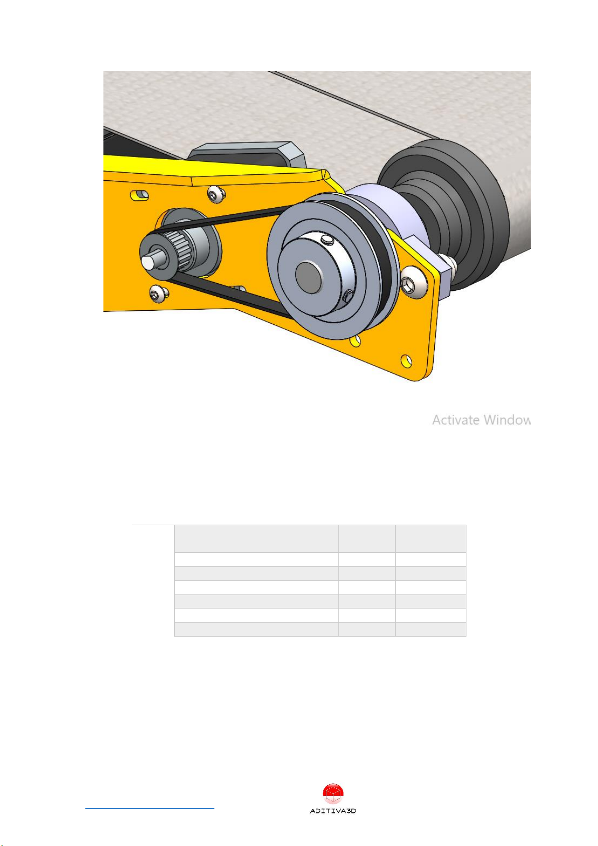
Belt motor installation: On the LEFT FRONT side of machine, take the Timing Pulley 60T,
bore 12mm GT2 and insert it on the end of the REAR ROLLER, then using the original Y
motor and pulley (using M4x8mm Screws and M4 slot nuts), proceed to install it. At this
point place the GT2 Timing Belt Closed Loop and align both pulleys, then adjust the
motor bracket in order to tension the closed loop belt. As shown in the next picture:
Ender 3 Conveyor 90 Belt Kit assembly manual P a g e 14 | 26
www.belt3dprinterkit.com
Figure 18 Belt motor assembly
Step 4.3 Installing Heatbed
Next items from the KIT will be used:
ITEM
ITEM DESCRIPTION
Quantity
Type
1
Original Heatbed with base plate
and leveling nuts and springs
1
Original Part
2
Heatbed mount plate
2
Kit
3
1020 ALU PROFILE 326mm
2
Kit
4
M4x8 mm SCREW
10
Kit
5
M4 Slot nut
10
Kit
6
M5x8 mm SCREW
4
Kit
7
M5 Slot nut
4
Kit
Preparing Heatbed base plate: Take original Heatbed and temporarily remove heating
element, then uninstall all Vslot Wheels from it, depending on your version of your 3d
printer, holes position and quantity may vary, but they always have at least two pairs of
aligned holes, as shown in the next picture, be aware of those holes since they will be
used to fix heatbed in the next steps:

Ender 3 Conveyor 90 Belt Kit assembly manual P a g e 15 | 26
www.belt3dprinterkit.com
Figure 19 Heatbed base plate without wheels and showing aligned holes pairs.
Installing support bars for heatbed: Using 1020 ALU PROFILE 326mm and M5x8 Screw
(04) and M5 Slot Nuts (04), fix the heated base plate with the mentioned bars, as shown
in the next picture:
Note: You might end up with a 90° rotated heatbed base plate (compared with its
original direction), but that’s totally fine.
Figure 20 1020 Alu profiles must be centered with Heatbed base plate.Check for aligned holes pairs. Distance
between Alu bars must be 40 mm.
Installing heatbed Assembly: Install heat bed element back again holding with Screws
and leveling nuts, compress the springs almost half their size.
Ender 3 Conveyor 90 Belt Kit assembly manual P a g e 16 | 26
www.belt3dprinterkit.com
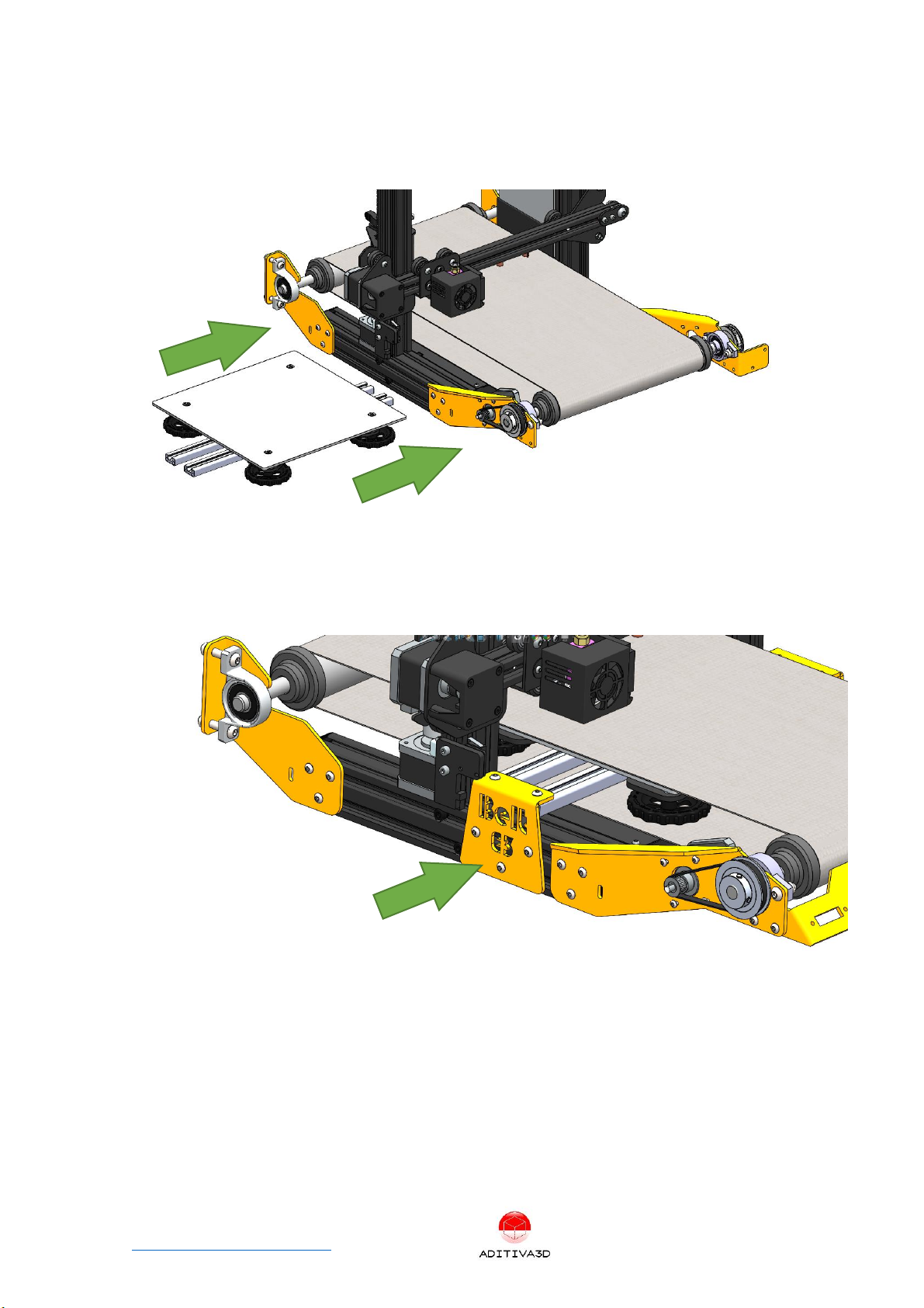
Proceed to insert Heated bed with support alu bars assembled, from the left side of
machine right under the tensioned BELT. (cable of heatbed will come out from the left
side to the machine and going to the electronic box)
Figure 21 Heatbed must be inserted inside belt
Using Heatbed mounting plates (Fixed by M4x8mm Screws + M4 Slot Nuts 5units on
each side), install Heatbed assembly as shown in the next picture:
Chapter 5 Finishing installation
Step 5.1 Screen installation
Install Screen on the right side of machine, using its original M5x8mm Screws, into the
threaded holes of the corner plate, at this point you can connect the screen cable:

Ender 3 Conveyor 90 Belt Kit assembly manual P a g e 17 | 26
www.belt3dprinterkit.com
Figure 22 Install back Screen into right position
Step 5.2 Face plate mounting
Install provided face plate into the front of the machine, using 4 M4x16 screws and M4
nylock nuts:
Figure 23 Install face plate, keeping a gap of 2mm from the belt
Chapter 6 Electronics and firmware
Step 6.1 Electronics
Connect all cables back to the motherboard, for stepper motors, use supplied 1-meter
cable motors for the Y motor, instead of original ones, IF NECESSARY:

Ender 3 Conveyor 90 Belt Kit assembly manual P a g e 18 | 26
www.belt3dprinterkit.com
Endstops: X and Z axis only have endstops, belt system doesn’t need one.
Z Endstop Installation: Using Z endstop assemble it with original bracket, and then
install it using a M4x8mm Screw and Slot nut, just cut bracket tab in order to let endstop
to go lower:
Figure 24 Cut Z endstop bracket tab
Use supplied Zip ties for cable management
Step 6.2 Firmware
Firmware will be provided for updating, there are a few methods out there to upgrade
your ender 3 firmware, but we recommend checking out Teaching Tech method:
https://youtu.be/fIl5X2ffdyo
Chapter 7 Calibrating bed and Z endstop
Step 7.1 Calibration
Bed leveling: After tensioning belt, use a large metal ruler or a level, and place it over
the belt, while supporting the ruler over the rollers, use the leveling nuts to adjust any
misalignment, repeat the process on both sides.

Ender 3 Conveyor 90 Belt Kit assembly manual P a g e 19 | 26
www.belt3dprinterkit.com
Figure 25 leveling bed left side
Figure 26 leveling bed right side
Z endstop Regulation: loosen Z endstop support, get X axis down to bed, place a piece
of paper between nozzle and belt, then push endstop back to X axis until switch is
pressed down finally adjust endstop support. Fine tune the position of the endstop if
the nozzle is too high or down.

Table of contents
Other ADITIVA 3D 3D Printer manuals


