ADITIVA 3D VORON BELT 350 KIT User manual


Voron 2.4 Conveyor 90 Belt Kit assembly manual P a g e 2 | 27
www.belt3dprinterkit.com
Content
Chapter 1 Intro 3
Step 1.1 What is included in this kit? 3
Step 1.2 Needed tools 3
Chapter 2 Disassembling Voron 2.4 front doors and heatbed 3
Step 2.1 Removing front door parts 4
Step 2.2 Removing Heatbed 4
Chapter 3 Preparing frame 5
Step 3.1 Installing bottom plates 5
Chapter 4 Installing Belt and Heatbed system 10
Step 4.1 Preparing rollers 10
Step 4.2 Installing Rollers and Belt 11
Step 4.3 Mounting Heatbed 16
Chapter 5 Finishing installation 18
Step 5.1 Belt holders mounting 18
Step 5.2 Face plate mounting 19
Step 5.3 Installing front STRIP CURTAIN 19
Chapter 6 Klipper and firmware settings 21
Voron 2.4 Conveyor 90 Belt Kit assembly manual P a g e 3 | 27
www.belt3dprinterkit.com
Chapter 1 Intro
Step 1.1 What is included in this kit?
In this kit you will find all the necessary parts for converting your regular Voron 2.4 3d printer
into a sequential Conveyor 3d printer. Parts lists are indicated on each step for better
understanding and guidance.
Step 1.2 Needed tools
In order to fully install this kit, you will need the next tools:
Set of Allen keys
Adjustable wrench or wrench kit
Measuring tape
Vernier caliper
Metal ruler (for alignment)
Chapter 2 Disassembling Voron 2.4 front doors and heatbed
In order to get ready to install this kit, you have to disassembly various segments of the original
3d printer, this part will guide you through entire process of preparation and getting ready to
install new parts.
*Please be aware some original parts will be discarded and won’t be installed.
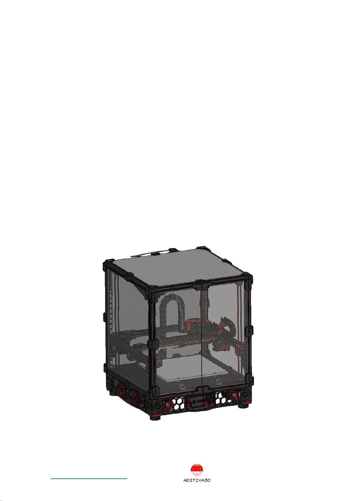
Figure 1. Assembled Heatbed
Voron 2.4 Conveyor 90 Belt Kit assembly manual P a g e 4 | 27
www.belt3dprinterkit.com
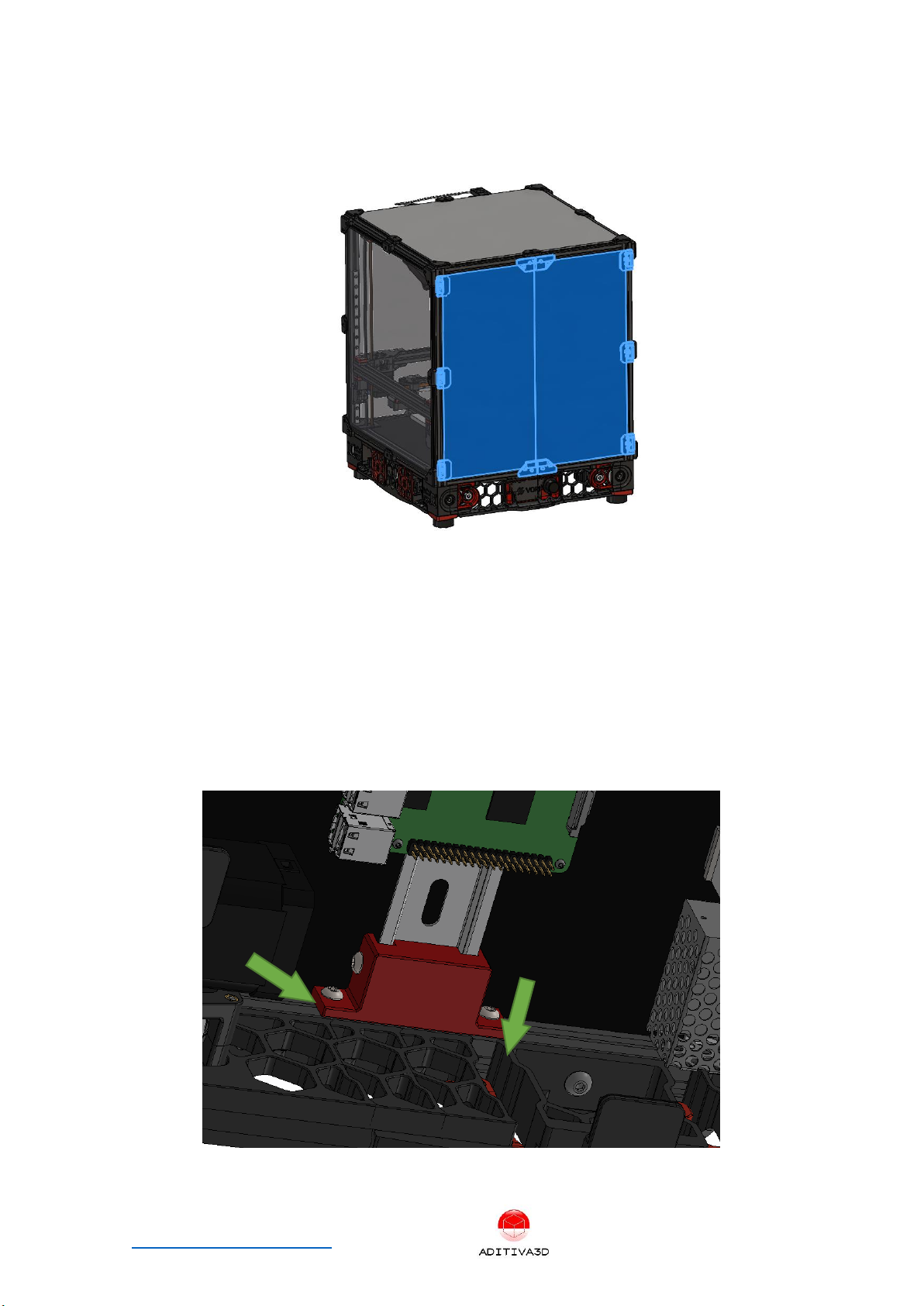
Step 2.1 Removing front door parts
Remove all brackets, panels and hinges from both front doors.
Figure 2 remove highlighted parts
Step 2.2 Removing Heatbed
Before starting to remove the heatbed, we need to secure both DIN rails that holds all
the electronic components, so we flip the printer carefully and remove the bottom
panel.
After that, we use the printed BRACKET_DIN_RAIL_X4.STL part and secure the DIN rails
using 4 units M4x8 screws and 2 units T-nuts on each bracket as shown in the next
picture.
Figure 3 Securing DIN rails before removing heatbed bars

Voron 2.4 Conveyor 90 Belt Kit assembly manual P a g e 5 | 27
www.belt3dprinterkit.com
We remove heating bed at this point, by releasing 4 units M3 bolts that holds it down,
it is highly recommended to remove any magnetic base plate, and clean the aluminum
heatbed with IPA in order to remove any glue from it:
*Note: Do not disconnect the heatbed from the electronics, just keep it loose for next
steps.
Figure 4 Removing heatbed screws
Now we can securely remove both 2020 aluminum bars that holds the heatbed, by
removing the 4 screws on each side, you have to disconnect cable from the Z endstop
unit, since it won’t be used:
Figure 5 Removing heatbed support bars
Chapter 3 Preparing frame
We are pretty much ready to install our kit.
Step 3.1 Installing bottom plates
Let’s identify each bracket part first:

Voron 2.4 Conveyor 90 Belt Kit assembly manual P a g e 7 | 27
www.belt3dprinterkit.com
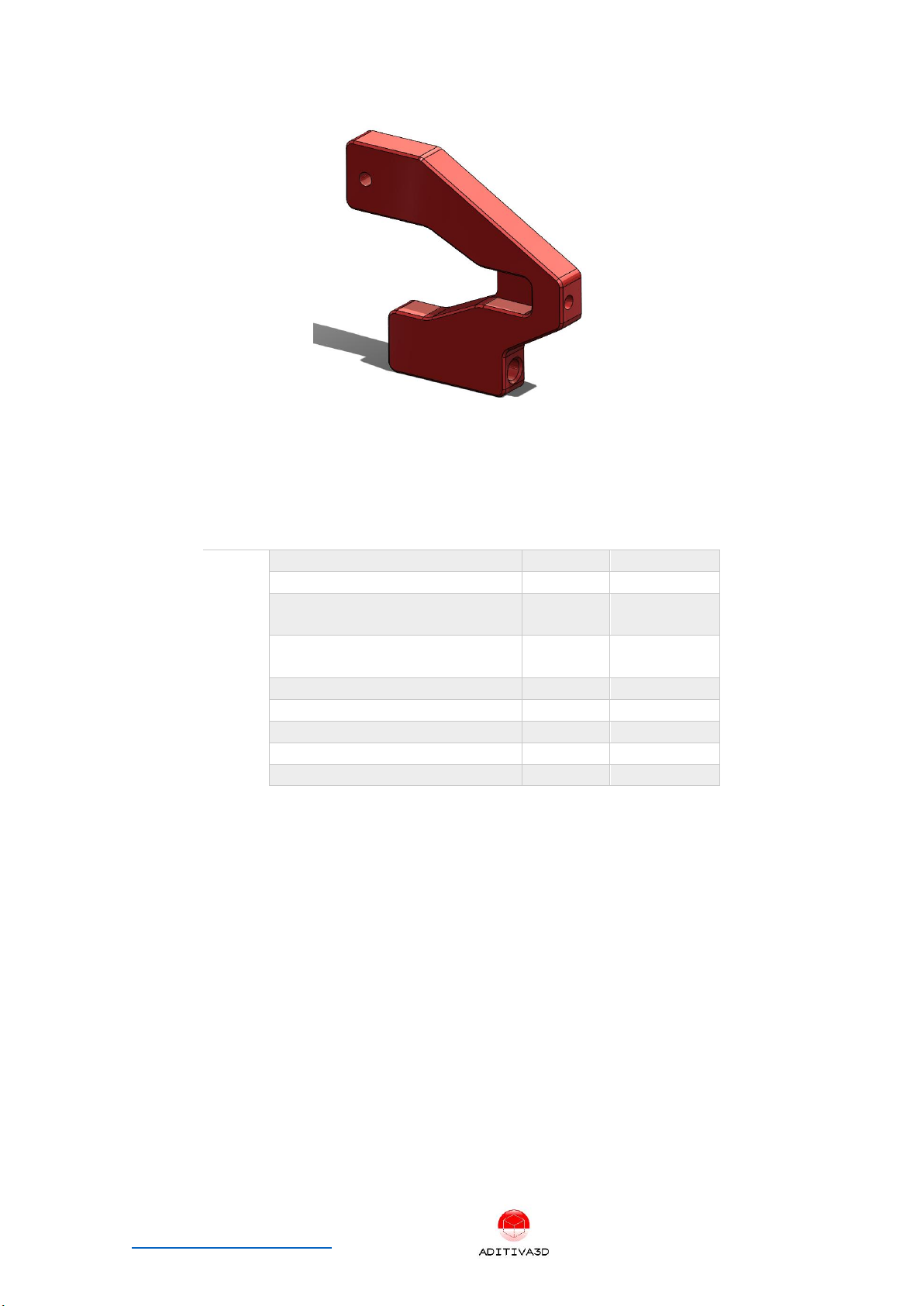
Figure 9: P4 VC90 CNC FRONT RIGHT BRACKET
Next items from the KIT will be used:
ITEM
ITEM DESCRIPTION
Quantity
Type
1
P1 VC90 BACK LEFT BRACKET
1
Kit
2
P2 VC90 BACK RIGHT BRACKET
1
Kit
3
P3 VC90 CNC FRONT LEFT
BRACKET
1
Kit
4
P4 VC90 CNC FRONT RIGHT
BRACKET
1
Kit
5
M5 x 20 mm Screw
2
Kit
6
M5 x 50 mm Screw
2
Kit
7
M5 T-Slot nut
4
Kit
8
M4 x 8 mm Screw
5
Kit
9
M4 T-Slot nut
5
Kit
Install 2 CNC bracket plates as shown in the next picture, M5 screws and M5 T-slot nuts
will be used, left and right sides must be assembled:

Voron 2.4 Conveyor 90 Belt Kit assembly manual P a g e 8 | 27
www.belt3dprinterkit.com
Figure 10 Installing front CNC brackets on each corner of bottom frame
Install 2 back bracket plates as shown in the next picture, M4x8 screws and M4 T-slot
nuts will be used, left and right sides must be assembled, they have to be installed right
next to the timing belt cover:
Note: If necessary and for easier mounting, is highly recommend to remove side panels
to reach those brackets and other parts from the conveyor system
1 M5x20 SCREW +
1 M5 T-SLOT NUT
1 M5x50 SCREW +
1 M5 T-SLOT NUT


Voron 2.4 Conveyor 90 Belt Kit assembly manual P a g e 10 | 27
www.belt3dprinterkit.com
Chapter 4 Installing Belt and Heatbed system
Figure 13 Belt system Assembly
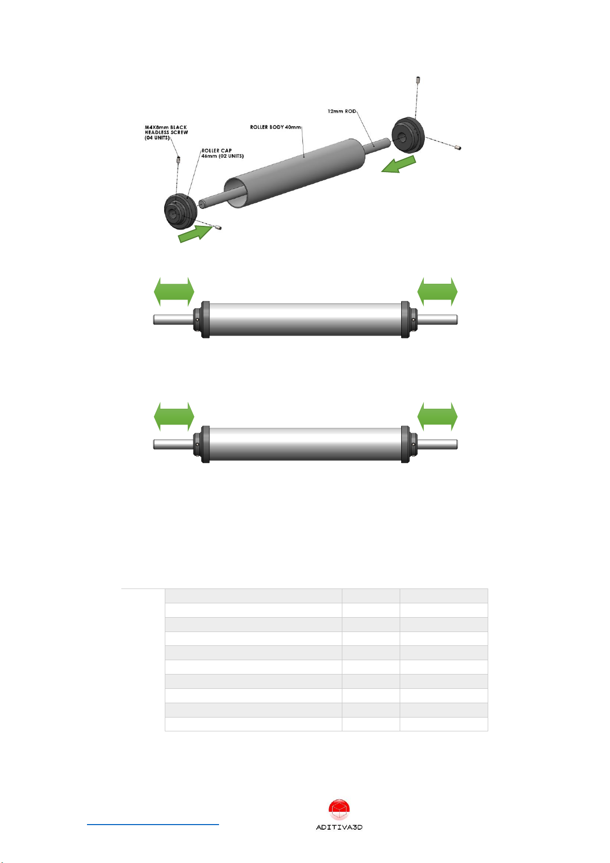
Step 4.1 Preparing rollers
Next items from the KIT will be used:
ITEM
ITEM DESCRIPTION
Quantity
Type
1
Roller BODY 40 mm
2
Kit
2
12 mm ROD
2
Kit
3
Roller Cap 46mm
4
Kit
4
M4x8mm Black Headless screw
8
Kit
Using all the mentioned parts, proceed to assemble them in the next order, first place
12mm ROD inside Rolle BODY 40mm, then insert Roller CAP 46mm on each end, making
sure it all fits very tight, keep in mind that 12mm ROD have to be placed according to
the next pictures. Finally using an allen key, proceed to secure both ROLLE CAP 46mm
with the M4x8mm BLACK HEADLESS SCREWS (02 on each side):
*Note: You have to repeat this process in order to get 2 rollers assembly.
Voron 2.4 Conveyor 90 Belt Kit assembly manual P a g e 11 | 27
www.belt3dprinterkit.com
Figure 14 Roller assembly components
Figure 15 Back roller mounting dimensions
Figure 16 Front roller mounting dimensions
Step 4.2 Installing Rollers and Belt
Next items from the KIT will be used:
ITEM
ITEM DESCRIPTION
Quantity
Type
1
Roller Assembly
2
Kit
2
FLANGE BEARING 12mm
4
Kit
3
M6x16mm SCREW
8
Kit
4
M6 NYLOCK NUT
4
Kit
5
BELT
1
Kit
6
Timing Pulley 60T, Bore 12mm GT2
1
Kit
7
GT2 Timing belt Closed Loop
1
Kit
8
Y MOTOR with GT2 PULLEY
1
Kit
9
M3X6 SCREW
4
Kit
10
M6 Knobs
2
Kit
Insert Flange Bearing 12mm on both sides of one of the Roller:
42 mm
22 mm
32 mm
32 mm

Voron 2.4 Conveyor 90 Belt Kit assembly manual P a g e 12 | 27
www.belt3dprinterkit.com
Mounting the back roller: at this point insert the back roller through the Conveyor
Belt:
Figure 17 Back roller mount
Figure 18 Fix the bearing with M6x16 Screw and M6 Hex nut, on both sides
FRONT ROLLER MOUNT: Take the FRONT ROLLER with FLANGE BEARINGS on it, install
it with M6x30 SCREWS into front CNC TENSIONERS MOVING ELEMENT:
2 M6x8 SCREW +
2 M6 HEX NUT

Voron 2.4 Conveyor 90 Belt Kit assembly manual P a g e 13 | 27
www.belt3dprinterkit.com
ROLLER HAS TO BE CENTERED!
Figure 19 Fix with M6x16 screws
Figure 20 Repeat with the right side
Insert this new FRONT ROLLER assembly through the Conveyor belt, and slide it on the
CNC TENSIONERS slot, and insert both sides M6 Knobs supplied in the kit:
Figure 21 Mounting front roller assembly

Voron 2.4 Conveyor 90 Belt Kit assembly manual P a g e 14 | 27
www.belt3dprinterkit.com
Insert both sides M6 Knobs supplied in the kit:
Figure 22 Inserting M6 Knobs on both sides
Belt tensioning:
One way to check for the right belt tension and alignment is to roll the belt by hand and it
have to move easy, smooth and straight without wobbling or needing to apply too much
force.
Figure 23 Measuring axles on right side
Voron 2.4 Conveyor 90 Belt Kit assembly manual P a g e 15 | 27
www.belt3dprinterkit.com
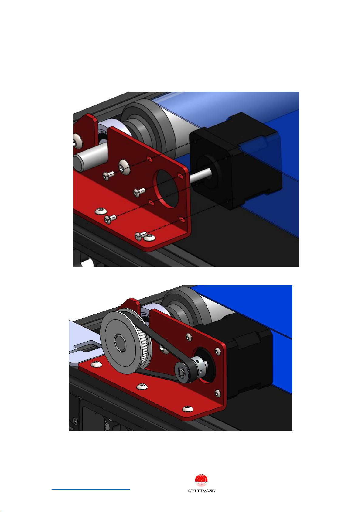
Belt motor installation: On the LEFT FRONT side of machine, take the Timing Pulley 60T,
bore 12mm GT2 and insert it on the end of the REAR ROLLER, then using the original Y
motor and pulley (using M4x8mm Screws and M4 slot nuts), proceed to install it. At this
point place the GT2 Timing Belt Closed Loop and align both pulleys, then adjust the
motor bracket in order to tension the closed loop belt. As shown in the next picture:
Figure 24 Insert included Nema 17, using M3x6 screws, don’t tight them yet
Figure 25 GT2 closed belt + 60T GT2 Pulley and 20T GT2 Pulley, tension and adjust motor screws
Voron 2.4 Conveyor 90 Belt Kit assembly manual P a g e 16 | 27
www.belt3dprinterkit.com
Step 4.3 Mounting Heatbed
Next items from the KIT will be used:
ITEM
ITEM DESCRIPTION
Quantity
Type
1
Original Heatbed without
magnetic sheet
1
Original Part
2
Heatbed mount plate
2
Kit
3
1020 ALU PROFILE
2
Kit
4
M4x8 mm SCREW
10
Kit
5
M4 Slot nut
10
Kit
6
M5x8 mm SCREW
4
Kit
7
M5 Slot nut
4
Kit
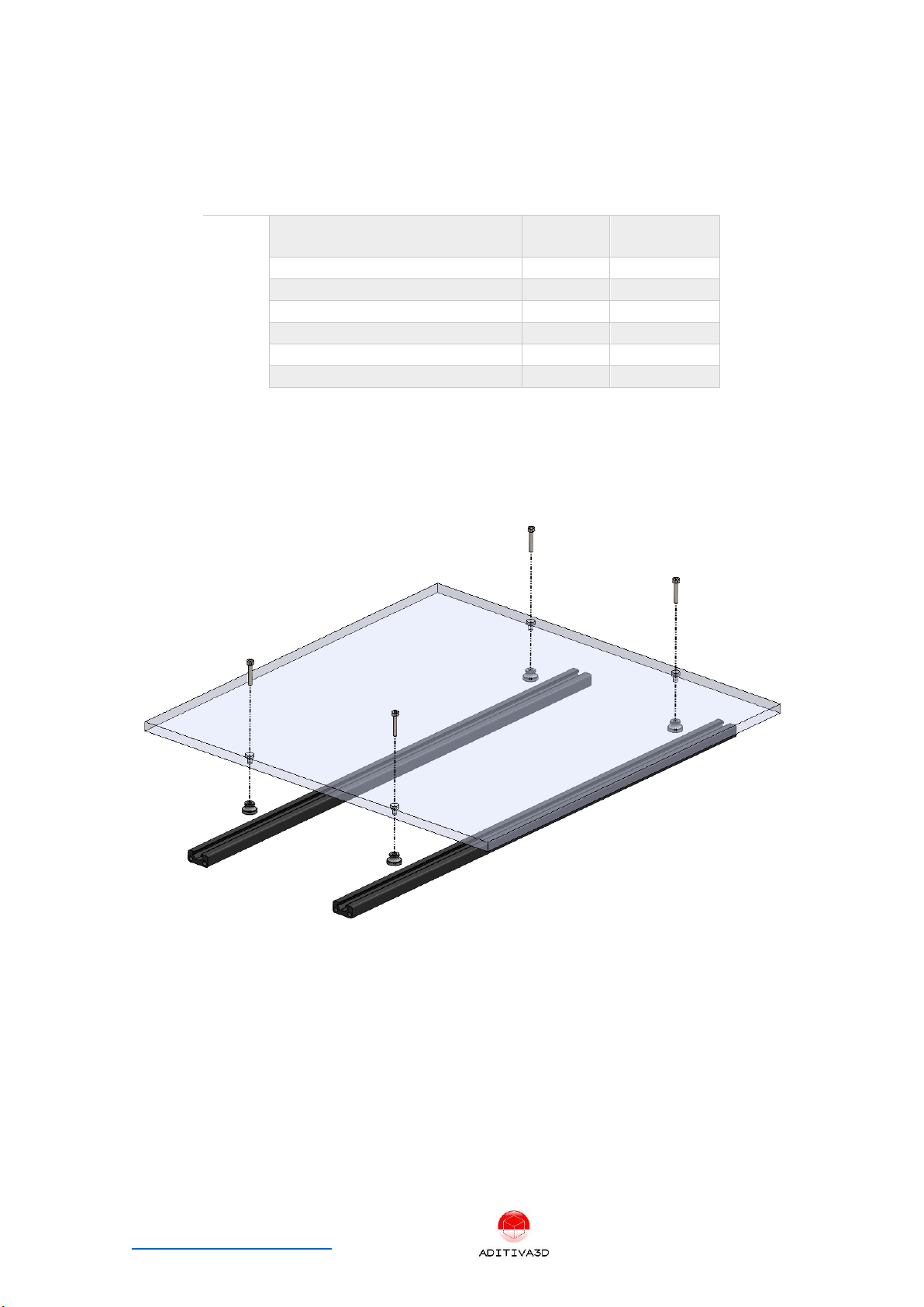
Preparing Heatbed base plate: Take original Heatbed, M4 knurled nuts, M3 screws and
M3 T-nuts, and mount over the 2 units 1020 ALU PROFILE as shown, heated bed has to
be centered:
Figure 26 Heatbed base plate without wheels and showing aligned holes pairs.
Installing heatbed Assembly: Install heat bed element back again.
Proceed to insert Heated bed with support alu bars assembled, from the left side of
machine right under the tensioned BELT. (cable of heatbed will come out from the left
side to the machine and going to the electronic compartment)


Voron 2.4 Conveyor 90 Belt Kit assembly manual P a g e 18 | 27
www.belt3dprinterkit.com
Figure 28 Internal dimension should be 110mm
Chapter 5 Finishing installation
Step 5.1 Belt holders mounting
Belt holders on each side of the Conveyor belt will help to reduce possible warping and
better stability for the belt once printing over it, in order to install them follow the
next scheme and repeat on the opposite side, after that slightly adjust the screws, in
order to get even and slightly pressure over the belt, belt holder should overlap the
belt for about 10 mm or less on each side:
1 M5x25 SCREW +
2 M5 WASHER +
1 SPRING
1 M5 T-NUT

Voron 2.4 Conveyor 90 Belt Kit assembly manual P a g e 19 | 27
www.belt3dprinterkit.com
Figure 29 Belt holder installed, repeat on the left side
Step 5.2 Face plate mounting
Install provided face plate into the front of the machine, using 2 units M5x8 screws
and M5 T-nuts, place it centered on the printer:
Figure 30 Install face plate, keeping a gap of 2mm from the belt
Step 5.3 Installing front STRIP CURTAIN
Strip curtain is required to keep heat inside the chamber, and also for letting parts to
come out easily from the belt.
Use supplied top bracket in order to fix all the strips to the top frame, using M4x8
screws and M4 T-nuts, you can use a piece of blue tape to pre-arrange them first over
a table for easy mounting, overlap is about 12mm for each strip:

Table of contents
Other ADITIVA 3D 3D Printer manuals


