ADITIVA 3D ENDER 3 BELT KIT User manual


Ender 3 Belt Kit assembly manual P a g e 2 | 43
www.belt3dprinterkit.com
Content
Chapter 1 Intro 4
Step 1.1 What is included in this kit? 4
Step 1.2 Additional printable parts 4
Step 1.3 Needed tools 4
Chapter 2 Disassembling ENDER 3 5
Step 2.1 Remove spool holder 5
Step 2.2 Remove power supply 6
Step 2.3 Disconnecting wires 6
Step 2.4 Removing original Z axis system 7
Step 2.5 Remove top side caps 8
Step 2.6 Removing original Top frame 8
Step 2.7 Removing screen 8
Step 2.8 Y axis and heatbed assembly 9
Step 2.9 Remove back endcaps 10
Chapter 3 Preparing frame 10
Step 3.1 Building Bottom Rear Frame 10
Step 3.2 Extending original bottom frame 11
Step 3.3 Installing bottom plates 12
Step 3.4 Preparing X axis 14
Step 3.5 Preparing Hotend 16
Step 3.6 Preparing top frame 18
Step 3.7 Installing Top and Bottom frame 19
Chapter 4 Installing movement mechanisms 21
Step 4.1 Top Corner Pulleys 21
Step 4.2 Installing diagonal movement Shaft and motor 22
Chapter 5 Installing Belt and Heatbed system 27
Step 5.1 Preparing rollers 27
Step 5.2 Installing Rollers and Belt 28
Step 5.3 Installing Heatbed 33
Chapter 6 Finishing installation 36
Step 6.1 Screen installation 36
Step 6.2 Power Supply installation 36
Step 6.3 Filament holder 37
Step 6.4 Belt Edge element 37


Ender 3 Belt Kit assembly manual P a g e 4 | 43
www.belt3dprinterkit.com
Chapter 1 Intro
Step 1.1 What is included in this kit?
In this kit you will find all the necessary parts for converting your regular Ender 3/PRO 3d printer
models into a Belt 3d printer (CR30 style), but some additional 3d printed parts might be
necessary as well (STL files will be provided). Parts lists are indicated on each step for better
understanding and guidance.
Step 1.2 Additional printable parts
There are few printable parts for finish this build, since they will be provided as STL digital
format, they are subject to upgrades and few more will be added in the future, please check
for regular updates.
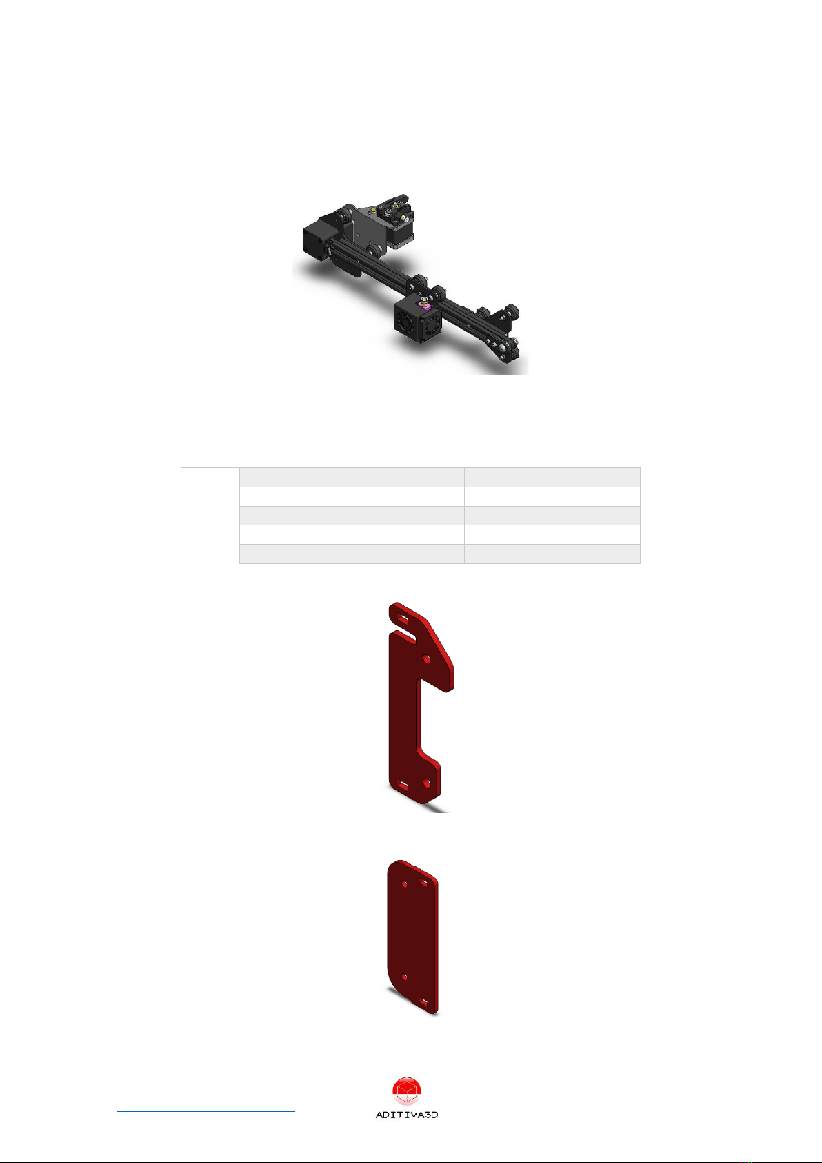
✓45° Axis endstop bracket
Figure 1 45° Axis endstop bracket
✓Belt Edge element
Figure 2 Belt Edge element
Step 1.3 Needed tools
In order to fully install this kit, you will need the next tools:
✓Set of Allen keys
✓Adjustable wrench or wrench kit
✓Measuring tape
✓Vernier caliper
✓Metal ruler (for alignment)
✓Arduino Uno and set of DuPont wires (for firmware flashing)
Ender 3 Belt Kit assembly manual P a g e 5 | 43
www.belt3dprinterkit.com
Chapter 2 Disassembling ENDER 3
In order to get ready to install this kit, you have to disassembly various segments of the original
3d printer, this part will guide you through entire process of preparation and getting ready to
install new parts.
In this part of the process, various electrical components will be temporarily disconnected for
practical purposes, you have to install them later though.
*Please be aware some original parts will be discarded and won’t be installed.
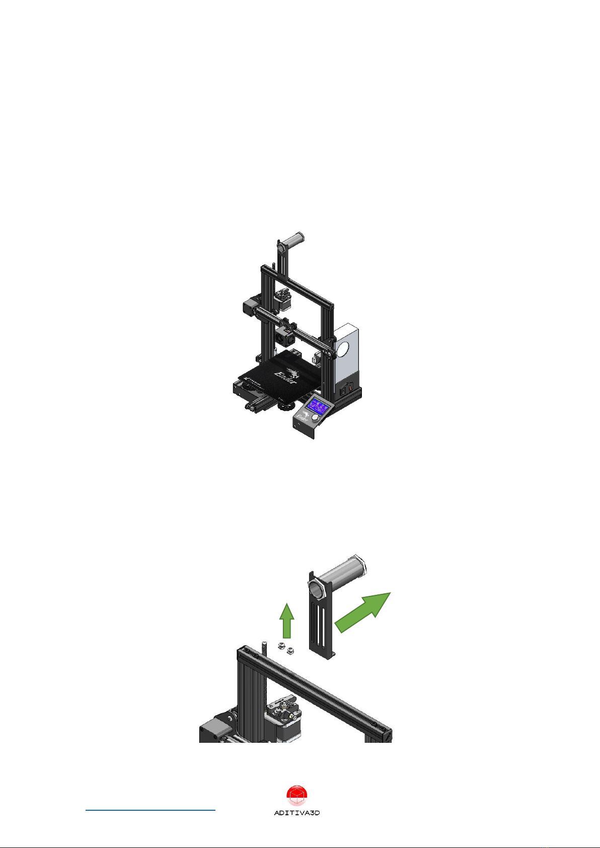
Figure 3. Assembled Ender 3
Step 2.1 Remove spool holder
✓Remove spool holder using allen key, spool holder is reused later, save it along with its
m4 screws and t-slot nuts.
Figure 4 Removing spool holder
Ender 3 Belt Kit assembly manual P a g e 6 | 43
www.belt3dprinterkit.com
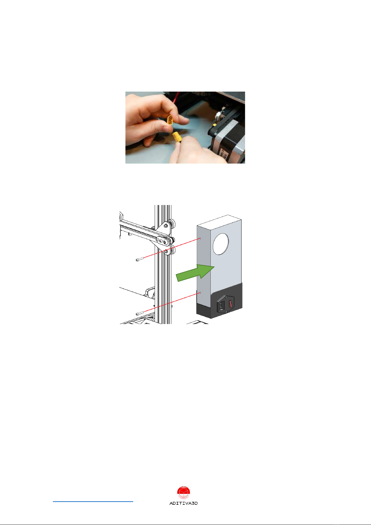
Step 2.2 Remove power supply
✓DISCONNECT ELECTRICAL POWER FROM THE MACHINE BEFORE DOING THIS STEP.
✓Disconnect power supply connector
Figure 5 disconnecting power supply from motherboard
✓Using an Allen key, remove the 2 x m4 screws that holds the power supply, save them
for later, since those will be used.
Figure 6 Removing power supply
Step 2.3 Disconnecting wires
✓DISCONNECT ELECTRICAL POWER FROM THE MACHINE BEFORE DOING THIS STEP.
✓Open up lid of electronics box, and proceed to disconnect all wires going to the hotend
harness, Z motor, extruder.
✓*Tip: take as many pictures as possible of connectors and wires in order to reconnect
later in assembly steps, labeling is also very useful.

Ender 3 Belt Kit assembly manual P a g e 7 | 43
www.belt3dprinterkit.com
Figure 7 Electronics box
✓Put lid back on its place and secure with its own screws.
Step 2.4 Removing original Z axis system
✓Disconnect Z motor cable.
✓Using an allen key remove Z motor bracket (m3 screws), leadscrew and Z nut (2 x m3
screws).
✓Also remove Z endstop (including plate), remove Z endstop cable as well.
Figure 8 Removing Z axis moving system
✓Items to discard: Z coupler, Z motor bracket, Z endstop bracket, leadscrew, brass nut.
✓Items to save for later use: Z motor, Z endstop (including its 2 x m3 screws)

Ender 3 Belt Kit assembly manual P a g e 8 | 43
www.belt3dprinterkit.com
Step 2.5 Remove top side caps
✓Remove aluminum bars caps, discard them.
Figure 9 End caps will be discarded
Step 2.6 Removing original Top frame
✓Using an Allen key, remove 4 M5 screws from the bottom of both Z columns.
✓Top frame and X axis assembly will be used, discard removed 4 x M5 screws.
Figure 10 Removing top frame and X axis system
Step 2.7 Removing screen

Ender 3 Belt Kit assembly manual P a g e 9 | 43
www.belt3dprinterkit.com
✓Remove cable from the back of the screen, please be aware of the connector position,
since it will be connected later.
Figure 11 disconnecting screen
✓Using an Allen key, remove 2 x m5 screws that holds screen in place.
✓Save both, screen assembly and screws for later use.
Figure 12 Removing screen
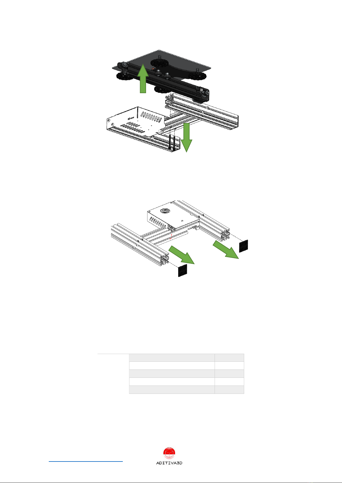
Step 2.8 Y axis and heatbed assembly
✓Using an Allen key, remove 2 x m5 screws that holds Y axis system with heatbed
assembly.
✓Save Y axis and heatbed assembly for later use, discard 2 x m5 screws.
Ender 3 Belt Kit assembly manual P a g e 10 | 43
www.belt3dprinterkit.com
Figure 13 Removing Y axis and heatbed
Step 2.9 Remove back endcaps
✓Please be sure to remove back endcaps of the 4040 aluminum bars from the bottom
frame.
Figure 14 Removing back endcaps
Chapter 3 Preparing frame
Step 3.1 Building Bottom Rear Frame
✓Next items from the KIT will be used:
ITEM
ITEM DESCRIPTION
Quantity
1
2040 V-Slot 346 mm
2
2
2020 V-Slot 290 mm
1
3
2020 Corner connector
2
4
M5 x 8 mm Screw
4
5
M5 Slot nut
4
✓Assemble the aluminum bars arranging them as shown in the next picture (Figure 15
and 16):

Ender 3 Belt Kit assembly manual P a g e 11 | 43
www.belt3dprinterkit.com
Figure 17 Bottom rear frame assembly
Figure 18 Corner joining detail
Step 3.2 Extending original bottom frame
✓Next items from the KIT and Original parts will be used:
ITEM
ITEM DESCRIPTION
Quantity
Type
1
Bottom Rear Frame Assembly
1
Assembly
2
Joint Plate
2
Kit
3
M4 x 8 mm Screw
12
Kit
4
M4 T-Slot nut
12
Kit
5
Bottom Original Frame
12
Original part
✓Assemble the Bottom Rear Frame Assembly and the Original Bottom Frame as shown
in the next picture (Figure), please be sure that both structures are very well aligned,
you can use a metal ruler or one of the 2040 V-Slot 500 mm provided in the kit, in order
to check for alignment on the bottom face of the final structure.
✓Using both Joint plates, M4 x 8 mm screws and M4 T-slot nuts, left and right sides must
be assembled, as shown in the next picture, Joint plate has to be centered with the joint:

Ender 3 Belt Kit assembly manual P a g e 12 | 43
www.belt3dprinterkit.com
Figure 19 Extended original bottom frame
Figure 20 Joint detail with Screws and T-slot nuts
Step 3.3 Installing bottom plates
✓Next items from the KIT and Original parts will be used:
ITEM
ITEM DESCRIPTION
Quantity
Type
1
Extended original bottom frame
1
Assembly
2
Left front plate
1
Kit
3
Right front plate
1
Kit
4
Left back plate
1
Kit
5
Right back plate
1
Kit
6
M4 x 8 mm Screw
12
Kit
7
M4 T-Slot nut
12
Kit
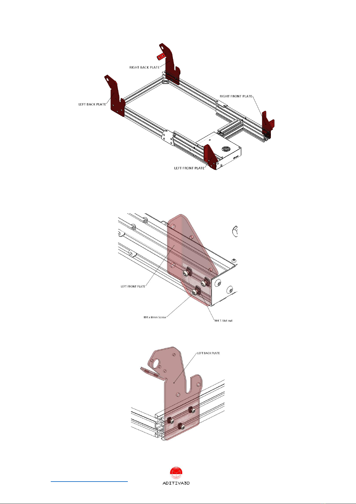
✓Install 4 plates as shown in the next picture, M4 x 8 mm screws and M4 T-slot nuts will
be used, left and right sides must be assembled:
Ender 3 Belt Kit assembly manual P a g e 13 | 43
www.belt3dprinterkit.com
Figure 21 Installing bottom plates on each corner of extended bottom frame
✓Plates will be installed right on the edge of each corner of the extended bottom frame.
Figure 22 Detail of front plate assembly (on the edge)
Figure 23 Detail of back plate assembly (on the edge)
Ender 3 Belt Kit assembly manual P a g e 14 | 43
www.belt3dprinterkit.com
Step 3.4 Preparing X axis
✓Take X axis assembly from original top frame and get it ready for modifications.
Figure 24 X axis assembly
✓Next items from the KIT and Original parts will be used:
ITEM
ITEM DESCRIPTION
Quantity
Type
1
X axis assembly
1
Original
2
Left X plate
1
Kit
3
Right X plate
1
Kit
4
M5 x 45 mm Screw
4
Kit
5
M5X8X8 ALUMINUM SPACER
2
Kit
Figure 25 Left X plate
Figure 26 Right X plate
Ender 3 Belt Kit assembly manual P a g e 15 | 43
www.belt3dprinterkit.com
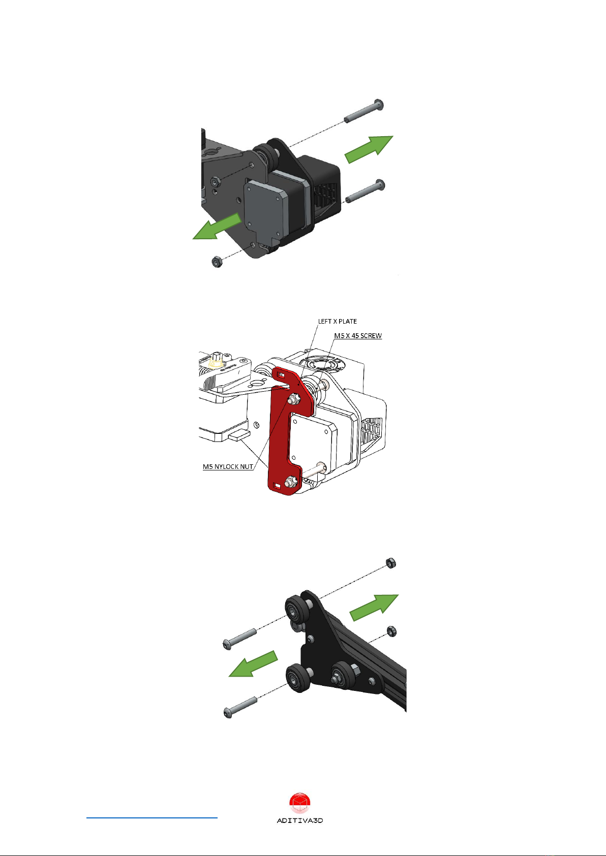
✓On the left side, remove M5 screws and Nylock nuts, discard only original M5 screws:
✓Install LEFT X PLATE using 2 M5 x 45 screws from the KIT and original Nylock nuts:
✓On the right side, remove M5 screws and Nylock nus, discard only original M5 screws:
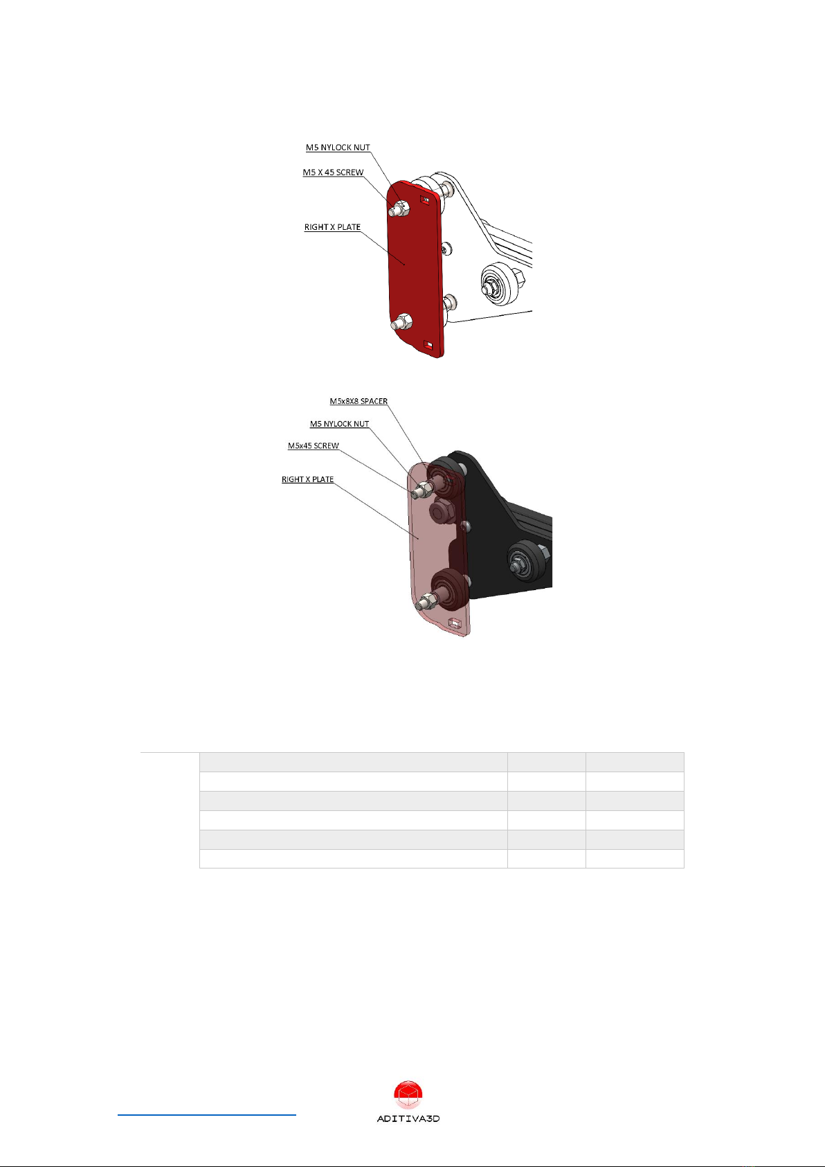
✓Install RIGHT X PLATE using 2 M5 x 45 screws from the KIT, 2 units M5X8X8
ALUMINUM SPACER from KIT (spacers to complete assembly for the plate) and
original Nylock nuts, as shown in the next picture:
Ender 3 Belt Kit assembly manual P a g e 16 | 43
www.belt3dprinterkit.com
Step 3.5 Preparing Hotend
✓Next items from the KIT and Original parts will be used:
ITEM
ITEM DESCRIPTION
Quantity
Type
1
Head plate
1
Kit
2
M3 x 6 mm Screw
2
ORIGINAL
3
M3 x 16 mm Screw
2
Kit
4
M3 x 25 mm Screw
2
Kit
5
M3X6X10 ALUMINUM SPACER LENGHT 10mm
2
Kit
6
M3X6X5 ALUMINUM SPACER LENGHT 5MM
2
Kit


Ender 3 Belt Kit assembly manual P a g e 18 | 43
www.belt3dprinterkit.com
Figure 29 Hotend 90° modification
Step 3.6 Preparing top frame
✓Next items from the KIT and Original parts will be used:
ITEM
ITEM DESCRIPTION
Quantity
Type
1
Original Top frame
1
Original
2
2040 V-Slot 500 mm NO HOLES
1
Kit
3
2040 V-Slot 500 mm with HOLES
1
Kit
4
Left Top corner plate
1
Kit
5
Right Top corner plate
1
Kit
6
M4 x 8 mm Screw
10
Kit
7
M4 Slot Nut
10
Kit
✓Using the previous materials, assembly them as shown in the next picture, please be
sure everything fits well and both bars are adjusted at 90° with the top frame, and
check the right position for each bar:

Ender 3 Belt Kit assembly manual P a g e 19 | 43
www.belt3dprinterkit.com
Figure 30 Modified top frame
Step 3.7 Installing Top and Bottom frame
✓Next items from the KIT and Original parts will be used:
ITEM
ITEM DESCRIPTION
Quantity
Type
1
Modified X axis assembly
1
-
2
Modified Top frame
1
-
3
M4 x 8 mm Screw
8
Kit
4
M4 Slot Nut
8
Kit
5
M5 x 8 mm Screw
4
Kit
✓Insert modified X assembly as shown in the next picture (Tip: using blue tape you can
secure X axis assembly to the top bar, and avoid it from dropping in the next assembly
steps):
Figure 31 Modified X axis inserted on the top frame assembly
✓Install top assembly frame using provided M4x8mm Screws (8) and M4 Slot nuts (8),
also M5x8mm Screws (4)

Table of contents
Other ADITIVA 3D 3D Printer manuals


