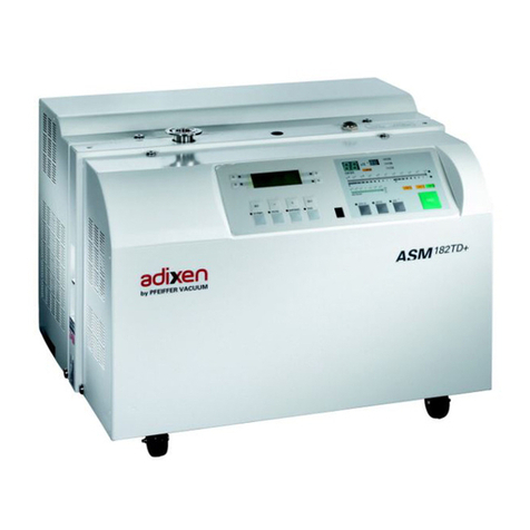
Adixen ASM 310 User manual

Operating instructions
Operating instructions
Translated from original version
Translated from original version
Portable leak detector
EN
EN
ASM 310


GB 03328 - Edition 02 - September 12
1/2
Dear customer,
You have just bought an adixen detector.
We would like to thank you and we are proud to count you among
our customers.
This product is a result of the experience acquired since many years
in vacuum and leak detection technology.
The applications of helium leak testing are extremely diversified
ranging from high-tech installation maintenance to high-speed testing
of industrial products.
Each product of the adixen detector range is designed to meet the
specific needs of each application:
• portability,
• high sensitivity,
• pumping capacity,
• pumping type.
adixen Vacuum Products - ASM 310 Operating instructions

2/2
GB 03328 - Edition 02 - September 12
This product complies with the requirements of European Directives,
listed in the Declaration of Conformity contained in G100 of this
manual. These Directives are amended by Directive 93/68/E.E.C
(E.C. Marking).
Copyright/Intellectual property:
The use of adixen products are subject to copyright and intellectual
property rights in force in any jurisdiction.
All rights reserved, including copying this document in whole or
any part without prior written authorization from adixen Vacuum
Products.
Specifications and information are subject to change without notice
by from adixen Vacuum Products.
adixen Vacuum Products - ASM 310 Operating instructions

GB 03311 - Edition 04 - February 13
1/2
General contents
ASM 310 - Operating instructions
manuel reference: 114916 - GB
edition: 04 - February 2013
Softwares versions:
L0232 ≥ v3.3 r00
L0322 ≥ v3.3 r00
L0264 ≥ v3.2 r00
L0224 ≥ v2.0 r00
Preliminary remarks Throughout this operating manual, you could find this type of
message “"Setting" menus arborescence C 600”: it refers
to a specific chapter of the operating manual. Please read it for
further information.
Chapter A INTRODUCTION
A 100 - Introduction
A 200 - About leak detection
A 400 - Accessories
A 500 - Technical characteristics
A 600 - Dimensions
Chapter B INSTALLATION
B 100 - Safety instructions
B 110 - Unpacking - Storage - Transport
B 112 - Product labelling
B 200 - Neutral gas purge and inlet vent connection
B 300 - Controlling the detector)
B 301 - RS 232
B 302 - 15 pin Interface
B 400 - Start-up
Chapter C OPERATION
C 100 - Getting started with the leak detector
C 110 - Perform a test
C 200 - Control panel
C 300 - Graphic display
C 400 - Settings
C 401 - Set points Menu
C 402 - Test Menu
C 403 - Spectro Menu
C 404 - Maintenance Menu
C 405 - Configuration Menu
C 406 - Advanced Menu
C 500 - Factory configuration of the leak detector parameters
C 600 - "Setting" menus arborescence
C 700 - Remote control (accessory)
C 900 - Long distance sniffer probe and Helium spray gun (accessories)
Chapter D MAINTENANCE - TROUBLESHOOTING
D 100 - Indicator lights and default display
D 200 - General troubleshooting guide
D 200/D 300 - General troubleshooting guide/Symptoms description
D 300 - Symptoms description
adixen Vacuum Products - ASM 310 Operating instructions

2/2
General contents
ASM 310 - Operating instructions
GB 03311 - Edition 04 - February 13
manuel reference: 114916 - GB
edition: 04 - February 2013
Softwares versions:
L0232 ≥ v3.3 r00
L0322 ≥ v3.3 r00
L0264 ≥ v3.2 r00
L0224 ≥ v2.0 r00
Chapter E MAINTENANCE SHEETS
E 100 - Maintenance operation instructions
E 110 - Access to internal components
E 120 - Table of preventive maintenance intervals
E 141 - Leak detector tightness checking
E 142 - Leak detector depollution
E 231 - P0411 Supervisor board
E 262 - P0482 Bluetooth board
E 410 - Autocalibration of the leak detector
E 411 - Calibration of a leak detector connected to a pumping group
E 412 - Calibrated leaks
E 413 - Replacement of the internal calibrated leak
E 430 - Analyzer cell maintenance
E 530 - Valves installation and maintenance
E 550 - Replacement of a fan
E 555 - Replacement of the purge filter
E 600 - Remote control
E 610 - Long distance sniffer probe and Helium spray gun (accessories)
E 710 - Roughing pump maintenance (MD1)
Chapter F COMPONENTS
F 000 - Spares parts - Instructions of use
F 001 - Service
F 100 - Tools
F 200 - Monitoring and display
F 300 - Power and electrical supply
F 400 - Automatic control system and electronic circuits
F 500 - Measurement
F 600 - Pumping
F 700 - Valves
F 800 - Pipes - Connections - Seals
F 900 - Cover
F 1000 - Options and accessories
F 1100 - Pictures of components
Chapter G APPENDIX
G 100 - Declaration of conformity
G 200 - Wiring diagram
G 400 - Long distance sniffer probe user manual
G 500 - Helium spray gun user manual
G 600 - Service
G 700 - Units
G 800 - Tools
adixen Vacuum Products - ASM 310 Operating instructions

GB 03304 - Edition 02 - September 12
1/1
Introduction
ASM 310 Operating instructions
Detailed contents
A
Preliminary remarks Throughout this operating manual, you could find this type of
message “"Setting" menus arborescence C 600”: it refers
to a specific chapter of the operating manual. Please read it for
further information.
A 100 Introduction
A 200 About leak detection
- Overview
- Vacuum circuit of a leak detector
- Test method
- Analyzer cell operating principle
- About helium and hydrogen
A 400 Accessories
- Accessories Common to all leak detectors
- Specific accessories to one or several leak detectors
A 500 Technical characteristics
A 600 Dimensions
adixen Vacuum Products - ASM 310 Operating instructions

GB 03322 - Edition 03 - February 13
1/1
A 100
Introduction
Congratulations, you have just acquired a unique dry helium leak
detector truly portable: the ASM 310.
The ASM 310 is the lightest unit of its category (less than 48 lbs)
that offers the following features:
1 cfm (1.7 m3/h) dry and clean roughing capacity,
1.1 l/s helium pumping speed at the inlet of the unit,
New analyzer cell design that delivers 3 years of full operation
without any maintenance required,
Operator interface display 100 % customized to meet all
customers needs,
Data acquisition downloadable to a SD memory card for easy
storage and convenience (graphs as well as text),
Import capabilities such as pictures (bmp format).
Ideally suited for any leak testing applications where portability is a
Must, this unit will deliver more than you would expect. This is more
than a helium leak detector, it is now yours to discover and enjoy.
adixen Vacuum Products - ASM 310 Operating instructions

GB 03302 - Edition 03 - July 12
1/11
A 200
About leak detection
Overview Leak detection is used to detect micro-openings, porosities, permeation
through materials etc. The means of detection is a tracer gas: Helium.
This gas is so light that it can penetrate microscopic cracks very fast.
The analyzer cell measures helium partial pressure created by helium
molecules that come from the leaking parts. These molecules are
pumped in by the vacuum pumps of the helium leak detector and end
up inside the analyzer cell. This partial helium pressure is converted
into a flow rate. The analyzer cell is tuned to detect three gas species,
hydrogen (M2), helium isotope (M3) and helium (M4). For more
information on the operating principle, please go to the end of this
chapter.
The ASM 310 helium leak detector has a wide measuring range
capability. It can detect a leak as large as 10-2 mbar l/s down to a
leak as small as 3x10-11 mbar l/s.
A leak of 10-2 mbar l/s is equivalent to a bubble of 1 cc escaping a
part every 100 seconds.
A leak of 3x10-11 mbar l/s corresponds to a bubble of 1 cc escaping
a part every 1,050 years.
As for reference, please see below for more leak rate correlations.
For the same size crack, a part will leak out helium at different rates
based on the internal helium pressure. The greater the internal helium
pressure, the higher the leak rate.
Leak testing large leaks versus leak testing tiny leaks will require
different settings, for more information, please go to chapter C.
Leak
Rate
3x10-11
mbar l/s
1x10⁻¹⁰
mbar l/s
1x10-09
mbar l/s
1x10-08
mbar l/s
1x10-07
mbar l/s
1x10-06
mbar l/s
1x10⁻⁵
mbar l/s
1x10-04
mbar l/s
1x10-03
mbar l/s
1 cc
Bubble
over time
frame
1,050
years 317
years 31.7
years 3.17
years 116
days 11.6
days 1.2
day 2.7
hours 17
minutes
adixen Vacuum Products - ASM 310 Operating instructions

2/11
A 200
About leak detection
GB 03302 - Edition 03 - July 12
The general vacuum diagram of the leak detector is shown below.
A dynamic version of the vacuum diagram is available on the leak
detector display panel. Green valves indicate opened valves. Red
valves indicate closed valves.
Vacuum circuit of a
leak detector
Test Procedure:
nConnect the part to be tested at the inlet of the leak detector 1,
then press the [START/Stand by] key.
When the unit is not in test mode (stand-by or roughing mode), the
helium displayed corresponds to the internal helium background of the
unit.
nRoughing Mode: Valve 3opens and the primary pump evacuates
the inlet of the unit as well as the part connected to it.
nWhen the inlet pressure 2reaches the test cross over, the roughing
valve 3closes, the exhaust valve 6opens, the test valve 4opens.
The high vacuum is then connected to the inlet of the leak detector
taking care of the gas load. The analyzer cell 8will measure any
helium present. The value of the leak will be measured and displayed
on the control panel.
analyzer
cell
tested
part
8
6
secondary
pumping
exhaut
valve
7
primary
pumping
5
3
4
1
2
roughing
valve
test
valve
inlet pressure
gauge
inlet
C 200
General vacuum circuit
of a leak detector
Vacuum circuit of
the ASM 310
adixen Vacuum Products - ASM 310 Operating instructions

GB 03302 - Edition 03 - July 12
3/11
A 200
About leak detection
Test method
Choice Several test methods are possible.
The testing method is selected according to the test part and the
measurement range required:
Hard Vacuum test
Hard Vacuum test Sniffing test
C 402
The part can
be connected to
an evacuation line The part is sealed
BOMBING method
The sensitivity is limited by the
internal dead volume of the part as
well as on the bombing time and the
pressurization value.
Global test without possible location
of the leak.
SPRAY method
leak rate measurement from 5 · 10-12
to 10-1 mbar l/s and possibility of
locating the leak.
SNIFFING method
Minimum detectable leak of
10-7 mbar l/s and possibility of
locating the leak.
Its characteristics
allow it to be
evacuated
Its characteristics
allow it to be
pressurized with helium
or a mixture containing
helium
Its characteristics
allow it to be placed
in a vacuum
vessel
yes
yes yes yes
no
no
adixen Vacuum Products - ASM 310 Operating instructions

4/11
A 200
About leak detection
GB 03302 - Edition 03 - July 12
He
He
START
STAND-BY
START
STAND-BY
Spray method
Response time
When spraying starts, the leak signal is not displayed instantaneously
on the analyzer cell:
there is a response time which depends on the volume V being tested
and the helium pumping speed S of the system at the opening of the
part, according to the following relation:
T = V/S (T in second, V in litre, S in l/s)
T is the time required for the signal to reach 63 % of the final value.
This involves removing air from the part tested, connecting it to the
analyzer cell and then spraying helium over the outer surface.
The part is placed under a
cover, into which helium is
injected.
The leak cannot be located.
Potential leaking areas are
sprayed with helium.
The leak can be located.
Global test
part
spray probe
detector
Spray test
The detector measures the flow of helium penetrating the part.
Connection rules: refer to B 300
or part
detector
adixen Vacuum Products - ASM 310 Operating instructions

GB 03302 - Edition 03 - July 12
5/11
A 200
About leak detection
He
START
STAND-BY
He
START
STAND-BY
or
The sniffer probe is moved over
areas likely to contain leaks.
The leak can be located.
The signal supplied by the
analyzer is not a exact
measurement of the leak.
The sniffer probe only samples
part of the helium escaping
from the part. The sample
depends on the distance
separating the leak from the tip
of the probe.
The part is placed under a
cover containing a sniffer
probe.
The leak cannot be located.
The helium from the leak
accumulates over time inside the
cover. The detector measures
the concentration of helium.
Global test Local sniffing test
Sniffing method The test part is pressurized with helium. The detector, via a sniffer
probe samples the helium escaping from the part.
Global test is generally kept for gross leaks (> 10-3 mbar l/s). In 90 %
of uses, the sniffing method is used in local.
part
Sniffer probe
detector part detector
Sniffer probe
adixen Vacuum Products - ASM 310 Operating instructions

6/11
A 200
About leak detection
GB 03302 - Edition 03 - July 12
He
He
START
STAND-BY
The part is placed in a chamber containing pressurized helium.
The helium penetrates the part if it has a leak.
The part is then removed from the chamber and placed in another
vacuum chamber which is connected to the detector. The helium
escapes from the part through the leak and produces a signal.
This signal is not a direct measurement of the leak as the helium
pressure inside the part is difficult to determine. Several parts play an
important part such as: the pressurization time, the helium bombing
pressure, the internal volume, the aeration time, the size of the leak.
Please consult us for details about this method.
Bombing method This method is used for sealed objects that cannot be connected
directly to the detector (semiconductors, waterproof watches, etc.).
The "MIL-STD-883- Method 1014" standard allows to comprehend
parameters of this test. Before this test, it is necessary to do a gross
leak test to remove parts with a very gross leak.
part part
Chamber 1 Chamber 2
detector
adixen Vacuum Products - ASM 310 Operating instructions

GB 03302 - Edition 03 - July 12
7/11
A 200
About leak detection
Analyzer cell
operating principle
The analyzer cell works on the principle of mass spectrometry and is
set by default to the mass of helium (m/e = 4). Other gasses can be
used (helium 3 or hydrogene).
m/e = atomic mass of the particle/number of electrons lost on
ionization.
The principle of magnetic deflexion spectrometry is as follows.
The molecules of the gas being analyzed pass into an ionization
chamber 4where they are bombarded by an electron beam
generated by a heated iridium filament 5. A large number of the
molecules are transformed into ions.
6
He
2.5V
3 A
He
He
He
He
Stabilized power supply
Amplifier
He Leak Signal
4
5
1
"Heavy" ions
Electrons beam
"Light" ions
Helium ions
2
3
TARGET
+ 140 V adjustable
1 Triode electrode
2 Diaphragm
3 Braking electrode
4 Ionization chamber
5 Iridium filament
6 Spare filament
Magnetic field
Description
adixen Vacuum Products - ASM 310 Operating instructions

8/11
A 200
About leak detection
GB 03302 - Edition 03 - July 12
The iridium filament allows a good performance at high pressures and
a small overheating.
These ionized particles are accelerated by an electrical field.
They arrive in a zone subjected to a magnetic field which has the
property of deflecting the trajectories of the ions along different curves
according to the masses of those ions (to be more precised, according
to their m/e ratios). Thus the ions beam, which contained ions with
different masses, is divided into several beams, each containing only
ions with the same m/e ratio. For example, the helium ions (m/e = 4)
are separated from the lighter (H2+ or H1+, smaller beams) or heavier
ions (N2+ or O2+, bigger beam).
The triode electrode 1collects the ions which the mass is higher than
the tracer gas mass. The electronic current measured in this way
allows to calculate the total pressure in the analyzer cell.
Because there is a constant magnetic field (permanent magnet), the
accelerator electrical field is adjusted so that the tracer gas ions follow
a pre-determined trajectory (passing through diaphragm 2) and arrive
on the target at the input to a direct current amplifier.
In order to separate the helium ions from "noise" caused by other
ions, an electrode located in front of the target eliminates them. This
electrode 3 is called the "braking electrode".
The current of ions of the tracer gas is proportional to the partial
pressure this one in the installation and by measuring it we can find
the flow rate of the leak that has been detected.
It is essential that the total pressure in the analyzer cell is less than
10-3 mbar, so that the trajectories of the electrons and the ions are not
disturbed by residual molecules.
There is a spare iridium filament 6in the analyzer cell.
adixen Vacuum Products - ASM 310 Operating instructions

GB 03302 - Edition 03 - July 12
9/11
A 200
About leak detection
Design Great care has been taken with the design of the 3rd generation cell
in order to repeatedly obtain the same characteristics and to achieve
excellent stability:
- the metal parts are made of stainless steel,
- the filament holder is made of machined aluminium and filament
iridium,
- there is an integrated amplifier.
The cell assembly is composed of:
nThe vacuum chamber:
The analyzer cell vacuum chamber is made of light alloy (aluminium).
nThe main cover function is to contain and position the following 3
modules:
-ionisation module: "ions" generation,
- braking module: ions sorting and dispersed ions suppression,
- equipped plate module: recepted ions amplification.
nThe preamplifier and its associated electronics:
-Power supply board: delivers power to all the components
-Measure board: Treat and convert the signal into a digital signal
(semi-log form).
-Preamp board: preamplification and mechanical interface.
adixen Vacuum Products - ASM 310 Operating instructions

10/11
A 200
About leak detection
GB 03302 - Edition 03 - July 12
Helium is the second most common element in the universe,
representing about 23 % of the total matter. 76 % is Hydrogen. All
other elements represent an insignificantly small fraction of the total.
Helium is a 100 % green gas and has absolutely no environmental
impact on the atmosphere.
Helium was discovered by spectroscopy in a solar eclipse on August
18, 1868. The discovery in the sun’s chronosphere gave the new
element its name: “helios” in Greek means “sun”. While Helium is
very common in the universe most of it is in the stars: on earth it is
actually not abundant. Since it is so light all the Helium present during
the formation of earth escaped to space.
Helium is created deep in the earth from the radioactive decay of
uranium and thorium which also gives the earth its internal heat. On
earth Helium was discovered in 1881 by spectroscopy of Mount
Vesuvio in Italy – the volcanic gases emanated by the mountain
showed the same lines in the spectrum as already known from the sun.
Helium concentration in the atmosphere is 5 times bigger than the
one of Krypton and 60 times higher than Xenon. The heavier noble
gases are isolated from air rectification. In contrary, Helium is “mined”
from natural gas and oil wells and stored. The annual world wide
production is ca. 3x10⁷m3or 4,500 tons.
Helium is constantly seeping up from the ground all around us, but it
is so light that almost all of it escapes into space fairly rapidly. On the
other hand there is a constant flow of Helium from space and the sun
to earth. This gives a dynamic equilibrium and is the reason for the
world wide constant concentration of 5 ppm Helium in air.
Helium is a very light colorless element and it is one of the six noble
gases which means it doesn’t react with anything for all practical
intents and purposes. It’s the most difficult gas to liquefy.
It’s used as an inert shield gas to protect things from oxidation – and
of course as leak detection tracer gas.
About helium and
hydrogen
Helium
adixen Vacuum Products - ASM 310 Operating instructions

GB 03302 - Edition 03 - July 12
11/11
A 200
About leak detection
Helium and leak detection:
which purity?
Helium is commercialized in many different purity levels, the highest
level of purity is requested from some laboratories for fundamental
researches or very accurate analyses.
The use of the Helium as a tracer gas into a mass spectrometer
doesn’t require such attention. A purity in the range of 97 % to 99 %
is enough.
There is absolutely no risk of accuracy lost or contamination for the
analyzer cell by using standard purity level of Helium gas.
Hydrogenated nitrogen If Hydrogen (H2) and Oxygen (O2) are mixed and heated, they react
and create water vapor (H2O). During this process more heat is
generated which may (if the concentration is high enough) ignite the
surrounding gas. If this process propagates, the gas explodes.
At low concentration of Hydrogen (< 4 % in air) the generated heat is
not enough to ignite the surrounding gas.
At concentrations in the range 4 to 12 % the combustion may
spread only if actions are taken to prevent the generated heat from
dissipating. It is a common misconception that hydrogen will explode
as soon as the concentration exceeds 4 %. It may explode only if
conditions are favorable for spontaneous propagation of combustion.
Never use pure hydrogen or a mixture with a hydrogen concentration
higher than 10 % to realize a "hydrogen" test as tracer gas.
If you use the recommended tracer gas of 5 % H2/ 95 % N2and mix
it with air there will either be too little hydrogen or too little oxygen
to constitute a combustible gas mixture. Hence this gas mixture is
classified as non flammable. The actual limit is 5.7 %.
The mixture 10 % H2/ 90 % N2is commonly used in the industry
because it is flammable only under certain conditions. This mixture is
however classified according to ISO 10156 as Flammable Gas and
should only be used after due safety considerations and approvals.
adixen Vacuum Products - ASM 310 Operating instructions

1/16
A 400
Accessories
GB 03329 - Edition 06 - February 12
Accessories Common
to all leak detectors
Calibrated leaks C1
Calibration accessory in sniffing C2
Remote control C3
Sniffer probe C4
Liquid sniffer probe C5
Helium spray gun C6
Locking clamp C7
Bombing chambers C8
Inlet filters C9
Specific accessories
to one or several leak
detectors
ASM 310 ASM 380 ASI 30
Transport case S1 •
Transport cart S2 •
Bottle support S3 •
Bluetooth (*) S4 • •
37 pin Input/Output board (*)
S5
37 pin Input/Output board with Wi-Fi (*) • •
37 pin Input/Output board with Ethernet (*)
Profibus board (*) S6 •
Industrial control panel (*) S7 •
Sniffing kit (*) S8 •
2005 IS primary pump S9 •
Interface extension kit S10 •
Power supply cords S11 • •
Measurement gauge S12 •
(*) also available in option
You can find via our Web Site free softwares designed to help you in
your applications. Refer to G 800.
adixen Vacuum Products - ASM 310 Operating instructions
Table of contents
Other Adixen Security Sensor manuals


