Adixen ATP 2300 M User manual
Operating Instructions
Operating Instructions
Translated from original version
Translated from original version
ATP 2300 M
Turbopumps
EN
EN
GB 02914 - Edition 05 - 03/2013
1/2
ATP 2300 M - Turbopump
Welcome
APPLICATIONS:
Semiconductor applications
Plasma etching, Ion implantation, Sputtering,
Plasma deposition.
Others Applications
Electron microscopes, Surface analysis,
Research and development, High energy physics,
Space simulation, Accelerators, Coating.
ADVANTAGES:
High pumping speed for light gases - High throughput - Quiet
and clean vacuum - Corrosion proof - High MTBF - Minimum size,
volume and weight - Smart and compact electronic controller -
Reliability - Maintenance free - Battery free - Easy integration.
Dear Customer,
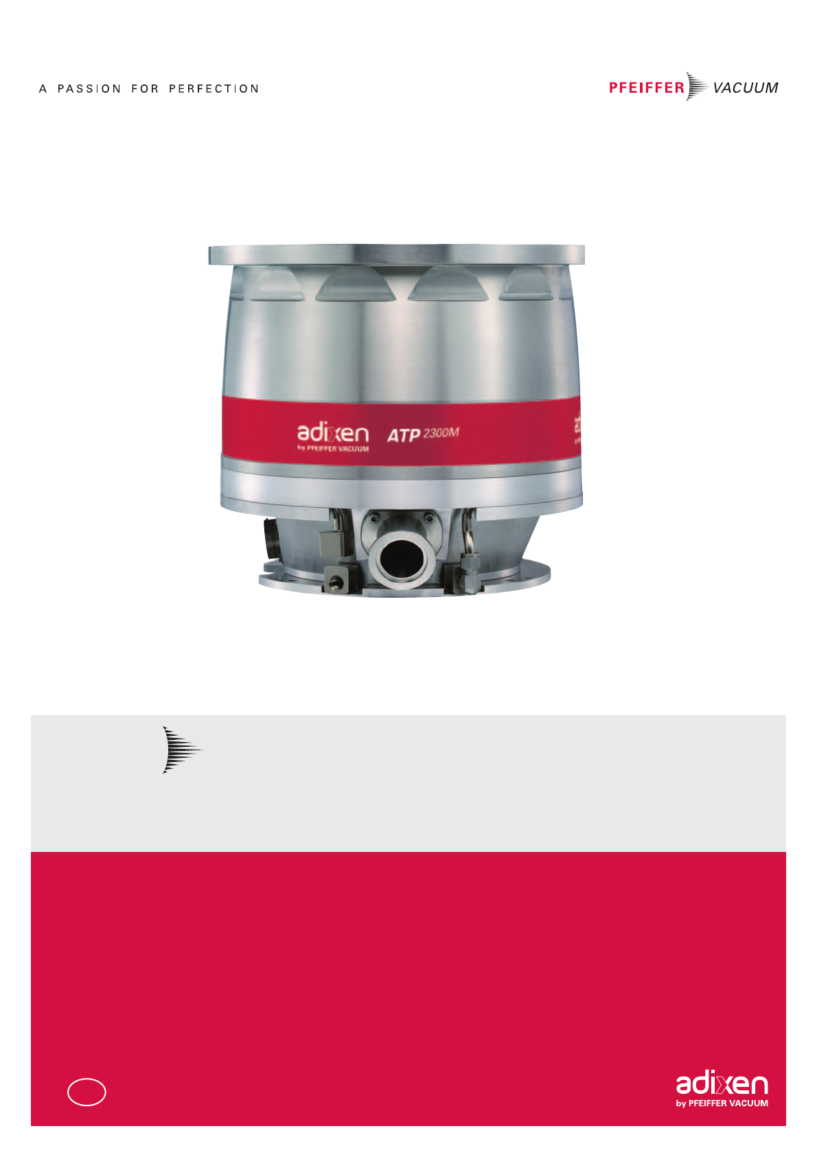
You have just purchased
an adixen Magnetically
turbopump.
We would like to thank you
and are proud to count you
as one of our customers.
This product has benefited
from adixen Vacuum
Products many years of
experience in the field of
Turbopump design.
In order to ensure the best
possible performance of
the equipment and your
complete satisfaction in
using it, we advise you to
read this manual carefully
before any intervention
on your pump and to pay
particular attention to the
equipment installation and
start-up section.
This operating instruction manual includes only the instructions to connect
the pump to the equipment. Refer to the controller operating instructions
to power and use the pump (chapter B, C and D).
This pumping component is designed to gererate vacuum by pumping on
gases, but no liquids neither solids. It is dedicated for running in industrial
environments.
The integrator of this component must provide all operator safety measures
mainly against hot surfaces.
This pumping component must not operate in an area with risk of
explosion. Consult us to study a solution.
adixen Vacuum Products - Operating Instructions - ATP 2300 M

2/2
ATP 2300 M - Turbopumps
GB 02914 - Edition 05 - 03/2013
Copyright/Intellectual property:
The use of adixen products are subject to copyright
and intellectual property rights in force in any
jurisdiction.
All rights reserved, including copying this document in
whole or any part without prior written authorization
from adixen Vacuum Products.
Specifications and information are subject to change
without notice by adixen Vacuum Products.
This product complies with the requirements of European Directives, listed
in the Declaration of Conformity contained in sheet G100 of the controller
operating instructions.
adixen Vacuum Products - Operating Instructions - ATP 2300 M

GB 02915 - Edition 06 - 03/2013
1/2
General contents
ATP 2300 M Operating instructions
MANUAL REFERENCE:112419
EDITION: 06 - June 2013
Translated from original version
Chapter A INTRODUCTION
A 150 - Introduction to the ATP 2300 M
A 200 - Control loop of the pump
A 210 - The pump operating principle
A 400 - Technical characteristics of the pump
A 510 - The accessories of the pump
A 515 - Accessory dimensions
Chapter B START-UP
B 100 - Safety instructions for installation and controller installation
B 201 - Unpacking and storage of the pump
B 300 - Pump connections to an installation
B 310 - Inlet and exhaust connections
B 330 - Nitrogen purge and air inlet valve device connections
B 340 - Water cooling connection
B 401 - Typical electrical wiring diagram
Chapter C OPERATION
C 100 - Safety instructions for product use
Chapter D MAINTENANCE
D 100 - Safety instructions for product removal
D 150 - Maintenance frequency
Chapter E MAINTENANCE INSTRUCTIONS
E 50 - Replacement of the water valve coil
E 100 - Shipping procedure for contaminated pumps
Chapter F MAINTENANCE COMPONENTS
F 000 - Spare parts - Instructions of use
F 100 - First level maintenance parts
Chapter G APPENDIX
G 150 - Pumping curves
G 200 - Service
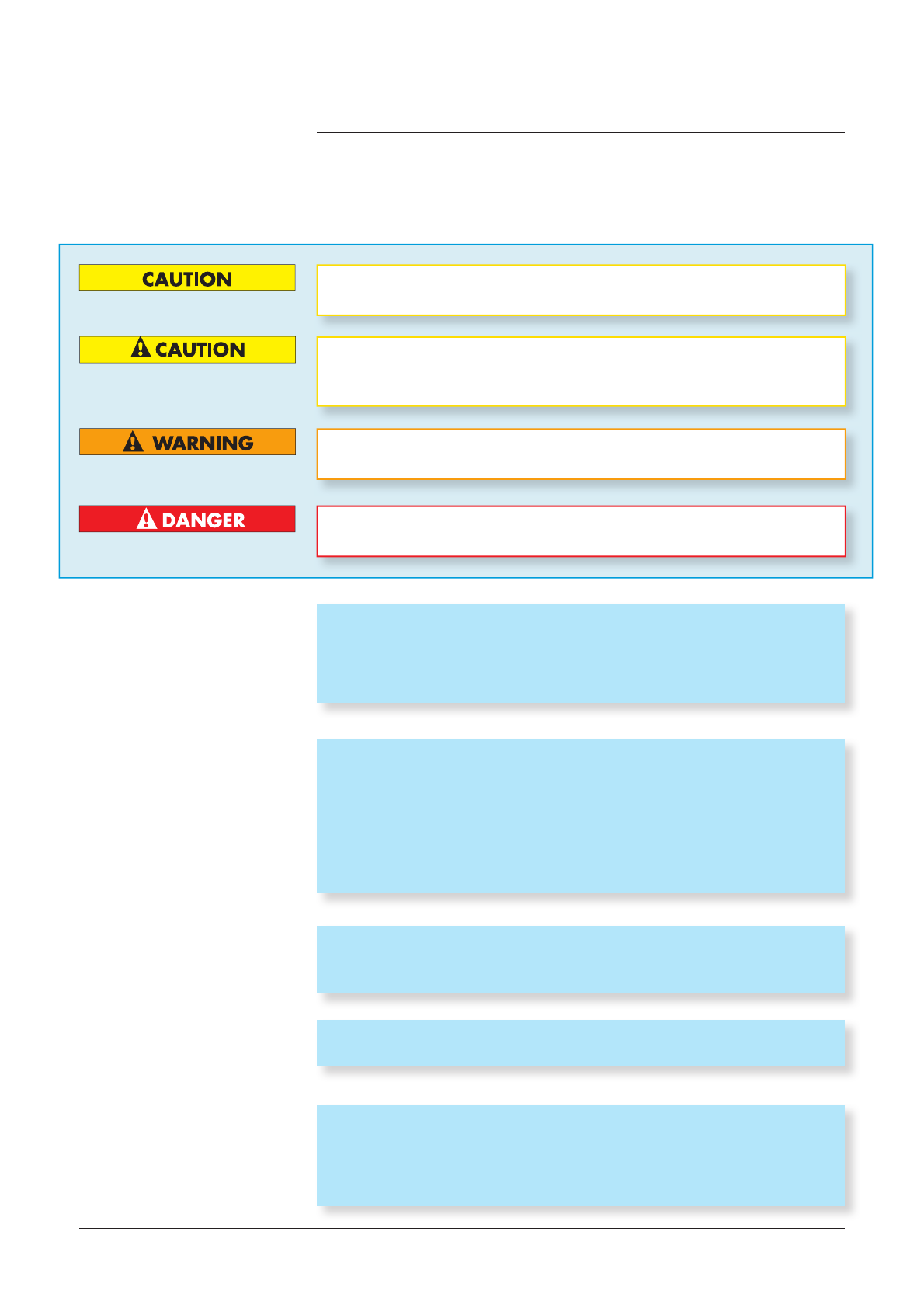
Indicates a potentially hazardous situation which, if not avoided, could
result in property damage.
Indicates a potentially hazardous situation which, if not avoided, could
result in moderate or minor injury. It may also be used to alert against
unsafe practices.
Indicates a potentially hazardous situation which, if not avoided, could
result in death or severe injury.
adixen Vacuum Products - Operating Instructions - ATP 2300 M

2/2
General contents
ATP 2300 M Operating instructions
GB 02915 - Edition 06 - 03/2013
MANUAL REFERENCE:112419
EDITION: 06 - June 2013
Translated from original version
Indicates an imminently hazardous situation that, if not avoided, will
result in death or severe injury (extreme situations).
The performance and operational safety of this product are guaranteed pro-
vided it is used normally in the operating conditions defined in this manual.
It is the customer’s task to:
- train operators to use the product if they do not speak the language the
manual is written in,
- ensure operators know the safe practices to apply when using the
product.
Before switching on the product, study the Operating instructions and make
sure you follow the safety instructions it gives. You can recognise these by
the “Caution”, “Warning” and “Danger” symbols.
Good practice tips and manufacturer’s recommendations are in a blue box.
Symbols, labels Description
Warning : hot surface
Warning : hazardous voltage
Caution : risk of danger. Refer to the operating
instructions before use
ON
OFF
Do not touch when the pump is running
Use of glove is recommended
Moving parts present
Heavy object
Lock the electrical connector before using the
pump and during operation
Purge Purge port
Pump exhaust Exhaust of the pump
Water Water cooling circuit connection
Water max Pr.7 bar/101 psi Max. Cooling water pressure
Direction of rotation of the pump
LOCK
adixen Vacuum Products - Operating Instructions - ATP 2300 M

GB 02916 - Edition 04 - 03/2013
1/1
Introduction
ATP 2300 M Operating instructions
Detailed contents
A
A 150 Introduction to the ATP 2300 M
A 200 Control loop of the pump
- 5 active axis
- Unbalanced force rejection control
A 210 The pump operating principle
- Pumping principle
- The Turbopump in an installation
- The back-up ball bearings
- No maintenance
- Battery free
- Variation of the pump rotational speed
A 400 Technical characteristics of the pump
A 510 The accessories of the pump
- Pump accessories
A 515 Accessory dimensions
- Purge valve (50 sccm) dimensions
- Air inlet valve dimensions
- Water valve dimensions
adixen Vacuum Products - Operating Instructions - ATP 2300 M

GB 02917 - Edition 03 - 03/2013
1/1
A 150
Introduction to the ATP 2300 M
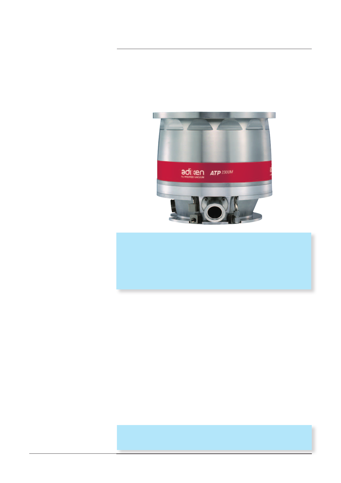
ATP 2300 M
A magnetically
levitated
turbomolecular pump
Five active axes
Rotor position control in 5 directions.
Unbalanced Force Rejection Control
Lowest possible levels of noise and vibration.
Automatic adjustment to any unbalance of the rotor, from very low
speed.
Maintenance free
Inert gas purge
Protect from corrosion the magnetic spindle.
Battery free
In case of a power failure, the pump motor acts like a generator
to transform the rotor energy into electrical power to supply the
controller.
Controllers The ATP 2300 M works with the OBC controller or with the
MAGPOWER controller.
(refer to corresponding operating instructions).
adixen Vacuum Products - Operating Instructions - ATP 2300 M
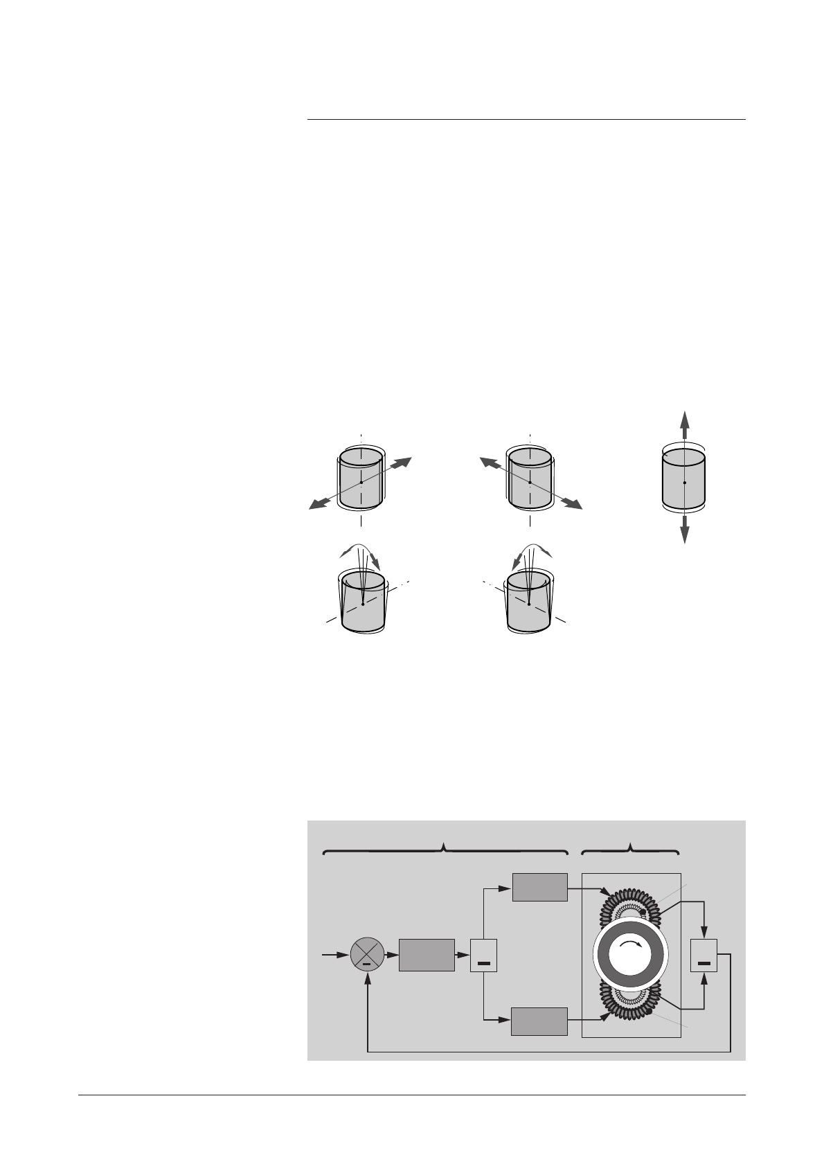
5 active axis The mobile assembly formed by the turbo rotor and the shaft is
known as the rotor. The rotor is driven by the motor and held
in suspension by magnetic fields generated by electromagnets
housed in an active bearing.
The mobile rotor has 5 axes of freedom monitored by 5 active
magnetic bearings.
+
Rotor
Stator
BearingElectronics
Power
amplifiers
Position of
Reference
Position return
Electro-
magnet
+
Correction
+
Position
sensor
Z
X
X
Y
Y
Movements in relation to these axes are monitored by position
sensors. According to the position data recorded, the controller
corrects differences to bring the rotor back to its optimum
position, by varying the current in electromagnets
3 controlled translations (X, Y, Z)
2 controlled tiltings (X, Y)
A 200
Control loop of the pump
1/2
GB 02721 - Edition 04 - Aug 07
adixen Vacuum Products - Operating Instructions - ATP 2300 M

Unbalanced force
rejection control
The unbalanced force rejection control is an electronic
function, that monitors the rotor position, allowing it to rotate
in its own axis of inertia.
Changes in the rotor balance, due to deposit built-up during
the life time of the pump, are automatically compensated by
the unbalanced force rejection control.
It ensures the lowest possible levels of noise and vibration.
Stator geometric axis
Rotor geometric axis
Rotor inertia axis
A 200
Control loop of the pump
2/2
GB 02721 - Edition 04 - Aug 07
adixen Vacuum Products - Operating Instructions - ATP 2300 M

GB 02918 - Edition 03 - 03/2013
1/2
A 210
The pump operating principle
Pumping principle The ATP 2300 M is a multi-staged turbomolecular pump,
recommended for light gases pumping.
The gas molecules of the vacuum system are trapped between the
rotating disks of the rotor and the stationary disks of the stator and
carried to the exhaust of the pump.
* The gas purge provides an excellent protection for corrosive applications and
ensures the rotor cooling.
The turbopump in an
installation
At the pump exhaust, the gases are evacuated to atmosphere by a
roughing pump.
Since the ATPM compression ratio is set by the design, the pumping
performances depend on the primary pump and on the installation.
ATMOSPHERIC
PRESSURE
Primary
pumping
INLET PRESSURE
Secondary
pumping
High vacuum Rough vacuum
Chamber
to be
pumped
Inlet
Magnetic levitated
bearings
Gas purge*
Cooling
Stator
Rotor
Motor
Dry back-up bearings
Exhaust
adixen Vacuum Products - Operating Instructions - ATP 2300 M

2/2
A 210
The pump operating principle
GB 02918 - Edition 03 - 03/2013
The back-up ball
bearings
No maintenance
Battery free
They are dry-lubricated ceramic ball bearings.
They are never used in normal operation, since the rotor is not in
contact with the ball bearings.
The back-up ball bearings are only used to protect the pump in
accidental air in-rushes, accidental shocks or power failure.
By design, the pump doesn’t include parts liable to wear and
doesn’t need preventive maintenance. However, the back-up
bearings used in case of accidental shut-downs have to be changed
when the controller indicates it: the percentage of landing time to
be deducted depends on the number of incidents ( D 150).
In case of a power failure, the motor acts like a generator, supplying
enough power for the magnetic bearings.
When the rotation speed is too low, the pump shuts down and
lands on the back-up ball bearings.
The ATPM pump rotation speed can be selected and set between a
minimum speed and the maximum speed.
This makes it possible to optimize pumping characteristics according
to each customer application (for example, high pressure pumping).
A distinction is made between the following speeds:
- reduced speed (STANDBY speed) which can be set between the
low speed value and the nominal speed.
- nominal speed : maximum speed preselected at factory.
Variation of the pump
rotational speed
adixen Vacuum Products - Operating Instructions - ATP 2300 M

GB 02919 - Edition 04 - Mar 13
1/3
A 400
Technical characteristics of the pump
CHARACTERISTICS UNIT ATP 2300 M
Flange (inlet) ISO-K DN 200 DN 250
Flange (exhaust) ISO KF DN 40
Pumping speed*
Ar l/s 1 400 1 900
H2 l/s 1 600 1 700
He l/s 1 750 2 050
N2 l/s 1 450 1 950
Compression rate
Ar > 1 · 108
H2 > 7 · 103
He > 1 · 105
N2 > 1 · 108
Gas throughput (1) (2)
Ar sccm 900
H2 sccm > 3 000
He sccm > 3 000
N2 sccm 2 200
Fore vacuum max. (3)
Ar hPa 1.7
H2 hPa 1.9
He hPa 1.5
N2 hPa 2.1
Inlet vacuum max. (2) Ar hPa 0.011
N2 hPa 0.04
He hPa 0.2
Ultimate pressure (4) hPa < 4 · 10-9
Nominal rotation speed tr/mn (Hz) 31 000 (517)
Standby speed tr/mn (Hz) from 15 000 (250) to nominal
speed 31 000 (517)
Sound pressure level db(A) < 46
Pump protection index IP 42
Controller power supply V 200-240 (50/60) (Hz)
Maximum leakage current (7) mA < 12
Max. start-up supply ** W < 1 000
Power consumption at ultimate pressure W < 130
Max. apparent start-up power ** VA < 1 250
Mounting orientation any
N2 purge flange ISO KF DN16
Integral leak rate hPa l/s < 5·10-8
* Without inlet screen.
** Value could be depend on controller type.
(1) At nominal rotational speed, water temperature = 25 °C (M = cold ; MT = 65 °C).
(2) With a low exhaust pressure, depends on external conditions (water temperature, water flow, ambient temperature).
(not applicable for air cooling version).
(3) With ratio inlet pressure/exhaust pressure >100, max. throughput reduced.
(4) ISO/F flange, better with CFF flange.
adixen Vacuum Products - Operating Instructions - ATP 2300 M

2/3
A 400
Technical characteristics of the pump
GB 02919 - Edition 04 - Mar 13
CHARACTERISTICS UNIT ATP 2300 M
ISO-K DN 200 DN 250
Run-up time up to 90 % of nominal
rotation speed, with exhaust pressure
< 0,1 hPa **
min < 8
Maximum baking temperature °C 120
Recommended purge flow rate sccm 50
Vibration level at nominal speed μm < 0,01
Maximum water line pressure hPa 7·103
Weight of the pump (kg) lb (52) 112
Recommended backing pump adixen ADP / ADS
Cooling water flow rate l/h 60
Water temperature (5) °C 15 < T < 40
Environmental conditions:
- Ambient operating temperature (6) °C 5 < T < 45
- Use of the product Indoor only
- Maximum altitude m/ft 2 000/6 562
- Accept transient over voltages typi-
cally present on the main supply
Catégory II
- Pollution degree applicable 2
- Maximum relative humidity (8) 80 %
Three phase motor characteristics
(max values): **
- Voltage between phases
- Supply frequency
- Phase current
Vrms
Hz
A
36
1033
9.7
(5) Over 25 °C apply a derating on continuous max flow.
(6) Not applicable for air cooling version.
(7) Not all leakage current is necessary evacuated through the earth wire; it depends on the pump earth connect regarding the
equipment to which the pump is connected.
(8) Maximum relative humidity 80 % for temperatures up to 31 °C, decreasing linearly to 50 % relative humidity at 40 °C.
adixen Vacuum Products - Operating Instructions - ATP 2300 M
GB 02919 - Edition 04 - Mar 13
3/3
A 400
Technical characteristics of the pump
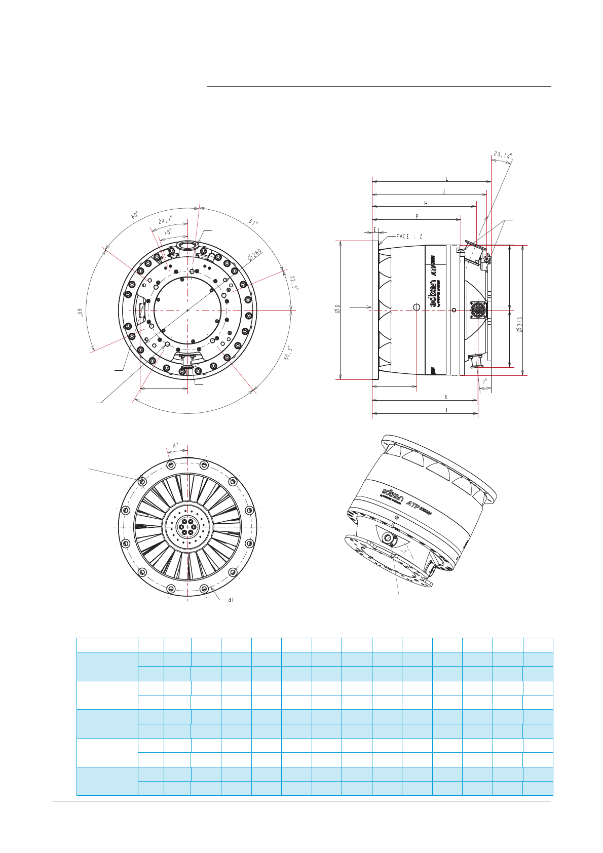
Dimensions
Inlet flange E H I J K L P D d1 d2 N A° CG
DN 250 ISO-F
mm 16,00 253,30 257,90 278,20 255,60 289,20 215,20 335,00 310,00 11,00 12,00 15° 133,70
inch 0.63 9.97 10.15 10.95 10.06 11.39 8.47 13.19 12.20 0.43 12 15° 5.26
DN 250 ISO-K
mm 12,00 253,30 257,90 278,20 255,60 289,20 215,20 290 - - - - 145,50
inch 0.47 9.97 10.15 10.95 10.06 11.39 8.47 11.42 - - - -5.73
DN 250 CF-F
mm 26,00 297,30 301,90 322,20 299,60 333,20 259,20 306,00 284,00 8,50 32,00 5,625° 170,60
inch 1.02 11.7 11.89 13.08 11.79 13.12 10.20 12.05 11.18 0.33 32 5.625° 6.72
DN 200 ISO-F
mm 16,00 314,30 317,90 339,20 316,60 350,20 276,20 285 260,00 11,00 12,00 15° 178,50
inch 0.63 12.37 12.52 13.35 12.46 13.79 10.87 11.22 10.23 0.43 12 15° 7.03
DN 200 ISO-K
mm 12,00 314,30 317,90 339,20 316,60 350,20 276,20 240 - - - - 187,60
inch 0.47 12.37 12.52 13.35 12.46 13.79 10.87 9.45 - - - -7.39
Dimensions
Electrical power
Supply
6 Holes M10-6H along190
Depth max. = 29
Depth min. = 25
N2 purge
DN 16 ISO KF
Exhaust
DN 40 ISO KF
Inlet/Outlet water
1/4 NPT female
Out
115,5 / (4.55)
IN
138,6 / (5.45) 158.4 / (6.23)
Gravity center
(12.4)
(10.24)
Esquidistant along d1
N holes d2
Use one of the 4 screws of the purge port
to connect a fonctionanal earth
Diam.maxi. of the eyelet: 10.5 mm
adixen Vacuum Products - Operating Instructions - ATP 2300 M

GB 02992 - Edition 05 - 03/2013
1/2
A 510
The accessories of the pumps
Inlet screen This screen protects the pump against solid particles. It is integrated
into the pump housing.
DN 200 P/N
Convexe filter (S.steel) + clip (mesh size 4.5 mm) 108872
DN 250 P/N
Convexe filter (S.steel) + clip (mesh size 5 mm) 108762
Purge flow reduction
device
This device is used to reduce
the purge gas flow rate in
some processes.
Flow Reduction
device DN 16 * P/N
50 SCCM 066752
Isolation valve
at pump inlet
The secondary isolation valve is used to maintain the vacuum in the
chamber while the pump is reset to atmospheric pressure.
See the manufacturer’s catalog.
* For pumps equipped with purge
valve (see next page).
Pumps model Inlet
size DN
P/N for
ISO F Description P/N for CF-F Description
ATH 1603 M
200 110675
110676S
12 CHC M10x30
12 CHC M10x35 *
250 110675
110676S
12 CHC M10x30
12 CHC M10x35 *
ATH 2303 M
ATH 2300 MT
ATP 2300 M
200 114510 12 stub M10x35 * --
250 110034
110676S
12 CHC M10x30
12 CHC M10x35 * 118690 32 Studs M8x35
Bolt and washer kit
for pump installation
* With centering ring
adixen Vacuum Products - Operating Instructions - ATP 2300 M
2/2
A 510
The accessories of the pumps
GB 02992 - Edition 05 - 03/2013
Dimensions P/N
1 m A462403-010
3.5 m A462403-035
5 m A462403-050
10 m A462403-100
20 m A462403-200
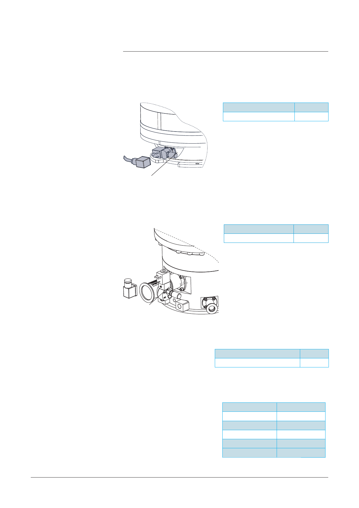
Purge valve * (50 sccm)
(driven by the customer
tool)
Air inlet valve *
Air inlet valve cables
and purge valve cables
(for pumps controlled by
Magpower)
The air inlet valve, powered by the
controller, is installed on the pump
exhaust port. It allows to reduce
the braking time of the pump to
put it at the atmospheric pressure.
It is a NC valve which is activated
when the pump nominal speed is
below 10 000 rpm.
Air inlet valve P/N
24 V DC 114280
Purge valve 50 sccm P/N
24 V DC 111921S
The gas purge provides an
excellent protection of the maglev
bearings for corrosive applications
and ensures the rotor cooling.
The purge of this valve can be
isolated during an air tightness
test.
* Provide a power line compatible with extra low voltage and safety standards
(SELV).
Dust filter
Dust filter
Water valve P/N
Water valve 108668
adixen Vacuum Products - Operating Instructions - ATP 2300 M

GB 04430 - Edition 04 - January 13
1/2
A 515
Accessory dimensions
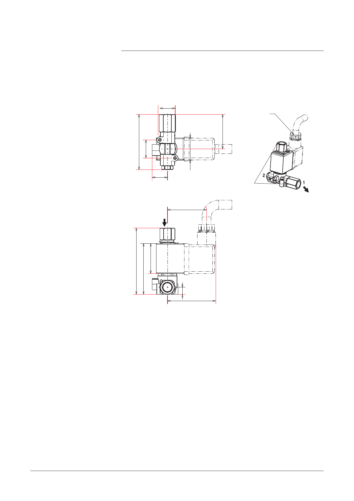
Purge valve (50 sccm)
dimensions mm (inch)
30 (1.18)
22 (0.86)
83.3 (3.28)
32 (1.26)
1/8 NPT
Can rotate Plug coil
Pump connection
62 (2.44)
82 (3.23)
65,5 (2.58)
18,5 (0.73)
65 (2.56)
1/8NPT female
connector
(air inlet)
DN 40 ISO KF
Pump connection
Connector for coil
(possible to rotate)
1/8 NPT female connector
Dust filter
Air inlet valve
dimensions
mm (inch)
adixen Vacuum Products - Operating Instructions - ATP 2300 M
2/2
A 515
Accessory dimensions
GB 04430 - Edition 04 - January 13
Water valve
dimensions
mm (inch)
Cable water valve
Scale 13/20
Inlet and outlet
1/8 NPT female
(0.86)
(2.15)
(0.59)
54,7
15
15
(0,59)
38,7
(1.88)
(2.58)
(1.52)
65,6
50,3 (1.98)
29,7 (1.17)
47,7
18(0.7)
34,2 (1.34)
(0.28) 22
7
OUT
IN
adixen Vacuum Products - Operating Instructions - ATP 2300 M

GB 02921 - Edition 04 - 03/2013
1/1
Start-up
ATP 2300 M Operating instructions
Detailed contents
B
B 100 Safety instructions for installation
B 201 Unpacking and storage of the pump
B 300 Pump connections to an installation
- Equipment installation conditions
- Pump connection instructions
- Why securing pump installation
- Worst case Turbo pump crash definitions
B 310 Inlet and exhaust connections
- Vacuum connections
- At inlet
- At exhaust
B 330 Nitrogen purge and air inlet valve device connections
- Characteristics of filtered dry nitrogen supply
- Purge device
- Air inlet valve with purge device
B 340 Water cooling connection
- Characteristics of water cooling
- Standard assembly
- Assembly with a water valve
B 401 Typical electrical wiring diagram
The electrical connections of the pump on the controller are showed on the
contoller operating manual.
adixen Vacuum Products - Operating Instructions - ATP 2300 M
GB 00731 - Edition 14 - Sept. 12
1/6
B 100
Safety instructions for pump and
controller installation
Indicates a potentially hazardous situation which, if not avoided, could
result in moderate or minor injury. It may also be used to alert against
unsafe practices.
Indicates a potentially hazardous situation which, if not avoided, could
result in property damage.
Indicates an imminently hazardous situation that, if not avoided, will result
in death or severe injury (extreme situations).
For emergencies and breakdowns, contact the manager of your local
service center (see addresses on our website).
We took care to provide you with a clean product. To keep it in this
condition, unpack it only in contamination free area and at final place of
use.
The performance and operational safety of this product are guaranteed
provided it is used normally in the operating conditions defined in this
manual.
It is the customer’s task to:
- train operators to use the product if they do not speak the language
the manual is written in,
- ensure operators know the safe practices to apply when using the
product.
Make sure the equipment shows no sign of transport damage. If it has
been damaged, take the necessary steps to record this with the carrier
and inform the manufacturer. In all cases, we recommend keeping the
packaging (reusable materials) for further transport of the equipment or
for prolonged storage.
Indicates a potentially hazardous situation which, if not avoided, could
result in death or severe injury.
Overview
For emergencies
Before switching on the product, study the Operating instructions and
make sure you follow the safety instructions. You can recognise these by
the ‘Caution’, ‘Warning’ and ‘Danger’ symbols.
Good practice tips and manufacturer’s recommendations are in a blue
box.
adixen Vacuum Products - Operating Instructions - ATP 2300 M
Table of contents
Other Adixen Water Pump manuals


Popular Water Pump manuals by other brands

PSG
PSG MOUVEX S6C Installation operation & maintenance

Grundfos
Grundfos Multilift MD Series Installation and operating instructions

Homa
Homa Chromatic Series Original instruction manual

TRITORC
TRITORC BEL-8 Series Operation and maintenance manual

SPERONI
SPERONI CAM 80/PA-HL operating instructions

Graco
Graco FIRE-BALL instructions

Tool Shed
Tool Shed TSPWP manual

Xylem
Xylem GOULDS AC8743 instruction manual

EUROM
EUROM SP400i manual

Pacific hydrostar
Pacific hydrostar 69297 Owner's manual & safety instructions

Amersham Pharmacia Biotech
Amersham Pharmacia Biotech P-910 instructions

Test Equipment Depot
Test Equipment Depot NRP6Di user guide


