ADJ UV LED BAR20 IR User manual

User Instructions
1/17
©2017 ADJ Products, LLC all rights reserved. Information,
specications, diagrams, images, and instructions herein are
subject to change without notice. ADJ Products, LLC logo and
identifying product names and numbers herein are trademarks
of ADJ Products, LLC. Copyright protection claimed includes all
forms and matters of copyrightable materials and information
now allowed by statutory or judicial law or hereinafter granted.
Product names used in this document may be trademarks or
registered trademarks of their respective companies and are
hereby acknowledged. All non-ADJ Products, LLC brands and
product names are trademarks or registered trademarks of their
respective companies.
ADJ Products, LLC and all aliated companies hereby dis-
claim any and all liabilities for property, equipment, building, and
electrical damages, injuries to any persons, and direct or indi-
rect economic loss associated with the use or reliance of any
information contained within this document, and/or as a result
of the improper, unsafe, unsucient and negligent assembly,
installation, rigging, and operation of this product.
Europe Energy Saving Notice
Energy Saving Matters (EuP 2009/125/EC)
Saving electric energy is a key to help protecting the enviroment.
Please turn o all electrical products when they are not in use. To
avoid power consumption in idle mode, disconnect all electrical
equipment from power when not in use. Thank you!
UV LED BAR20 IR

ADJ Products, LLC - www.adj.com - UV LED Bar20 IR Instruction Manual Page 3
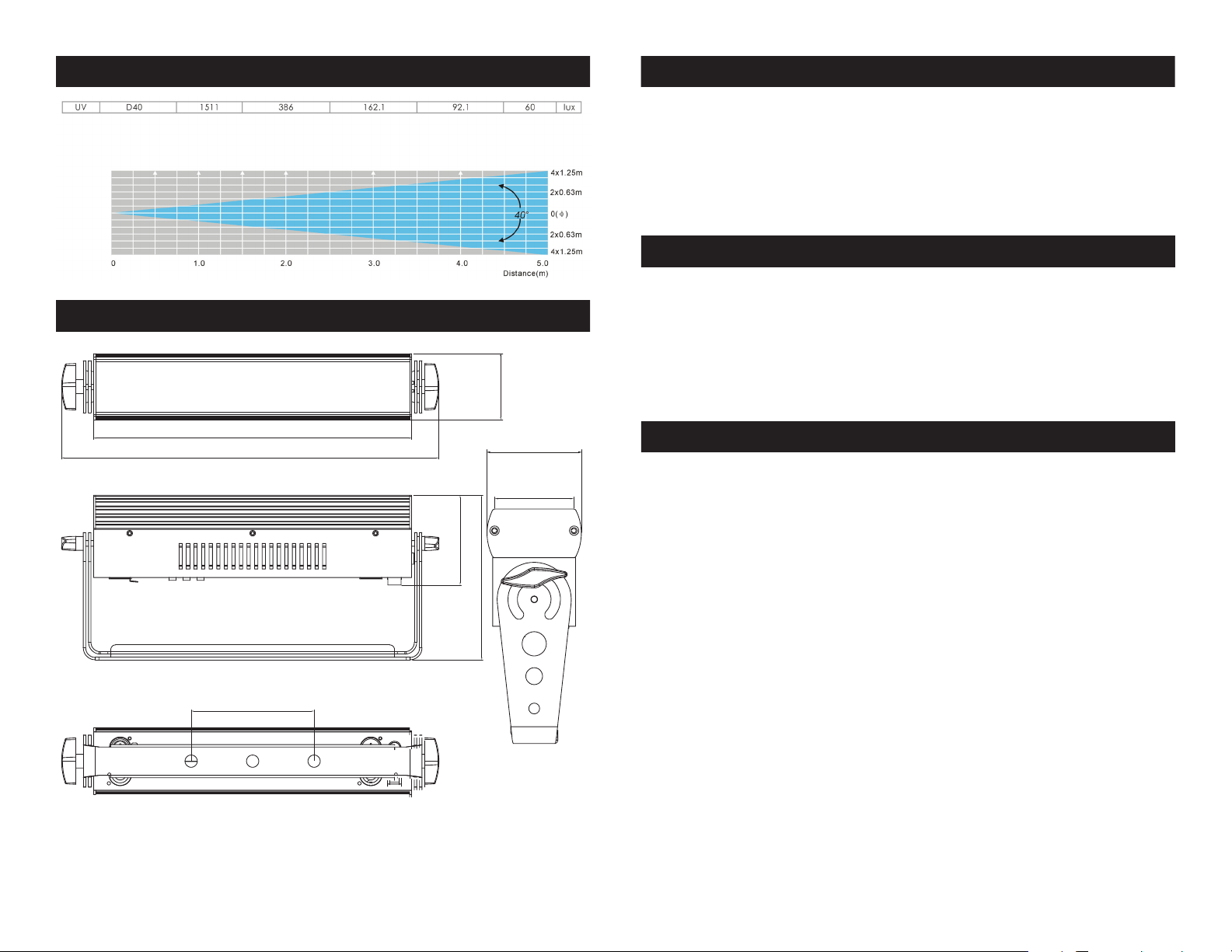
UV LED Bar20 IR Warranty Registration
The UV LED Bar20 IR carries a 2 year (730 days) limited warranty.
Please fill out the enclosed warranty card to validate your purchase
and warranty. You may also register your product online at www.
americandj.com. All returned service items whether under warranty or
not, must be freight pre-paid and accompany a return authorization
(R.A.) number. If the unit is under warranty you must provide a copy
of your proof of purchase invoice. Please contact ADJ customer sup-
port for a R.A. number.
UV LED Bar20 IR Features
To optimize the performance of this product, please read these operat-
ing instructions carefully to familiarize yourself with the basic operations
of this unit. These instructions contain important safety information
regarding the use and maintenance of this unit. Please keep this manual
with the unit, for future reference.
UV LED Bar20 IR General Instructions
• 4 Operating Modes
• Electronic Dimming 0-100%
• Built in Microphone
• DMX-512 protocol
• 3 DMX Channel Modes: 1 Channel Mode, 2 Channel Mode, & 3
Channel Mode
• Power Cord Daisy Chain (See page 15 for more info)
• UC IR Compatible & Airstream IR Compatible
UV LED Bar20 IR Cleaning
Due to fog residue, smoke, and dust cleaning the internal and exter-
nal optical lenses must be carried out periodically to optimize light
output.
1. Use normal glass cleaner and a soft cloth to wipe down the
outside casing.
2. Clean the external optics with glass cleaner and a soft cloth
every 20 days.
3. Always be sure to dry all parts completely before plugging
the unit back in.
Cleaning frequency depends on the environment in which the fixture
operates (i.e. smoke, fog residue, dust, dew).
UV LED Bar20 IR Introduction
ADJ Products, LLC - www.adj.com - UV LED Bar20 IR Instruction Manual Page 2
Unpacking: Thank you for purchasing the UV LED Bar20 IR by ADJ
Products, LLC. Every UV LED Bar20 IR has been thoroughly tested
and has been shipped in perfect operating condition. Carefully check
the shipping carton for damage that may have occurred during ship-
ping. If the carton appears to be damaged, carefully inspect your x-
ture for any damage and be sure all accessories necessary to operate
the unit has arrived intact. In the case damage has been found or parts
are missing, please contact our toll free customer support number for
further instructions. Do not return this unit to your dealer without rst
contacting customer support.
Introduction: The UV LED Bar20 IR is part of ADJ’s continuing pur-
suit for creating high quality affordable intelligent fixtures. The UV LED
Bar20 IR is a DMX intelligent LED color wash. This wash can be used
in a stand alone mode or connected in a Master/Slave conguration.
The unit can also be controlled via DMX controller. This unit has four
operating modes: Static mode, strobing mode, sound active mode,
and DMX controlled.
Customer Support: ADJ Products, LLC provides a toll free cus-
tomer support line, to provide set up help and to answer any question
should you encounter problems during your set up or initial operation.
You may also visit us on the web at www.adj.com for any comments
or suggestions. Service Hours are Monday through Friday 8:00 a.m. to
4:30 p.m. Pacic Standard Time.
Voice: (800) 322-6337
Fax: (323) 582-2941
To purchase parts online visit http://parts.americandj.com
Warning! To prevent or reduce the risk of electrical shock or re, do
not expose this unit to rain or moisture.
Caution! There are no user serviceable parts inside this unit. Do not
attempt any repairs yourself, doing so will void your manufactures war-
ranty. In the unlikely event your unit may require service please contact
ADJ Products, LLC.
PLEASE recycle the shipping carton when ever possible.

UV LED Bar20 IR Safety Precautions
ADJ Products, LLC - www.adj.com - UV LED Bar20 IR Instruction Manual Page 4 ADJ Products, LLC - www.adj.com - UV LED Bar20 IR Instruction Manual Page 5
• To reduce the risk of electrical shock or re, do not expose this unit
rain or moisture
• Do not spill water or other liquids into or on to your unit.
• Be sure that the local power outlet match that of the required volt-
age for your unit.
• Do not attempt to operate this unit if the power cord has been
frayed or broken. Do not attempt to remove or break o the ground
prong from the electrical cord. This prong is used to reduce the risk
of electrical shock and re in case of an internal short.
• Disconnect from main power before making any type of connection.
• Do not remove the cover under any conditions. There are no user
serviceable parts inside.
• Never operate this unit when it’s cover is removed.
• Never plug this unit in to a dimmer pack
• Always be sure to mount this unit in an area that will allow proper
ventilation. Allow about 6” (15cm) between this device and a wall.
• Do not attempt to operate this unit, if it becomes damaged.
• This unit is intended for indoor use only, use of this product out`
doors voids all warranties.
• During long periods of non-use, disconnect the unit’s main power.
• Always mount this unit in safe and stable matter.
• Power-supply cords should be routed so that they are not likely to
be walked on or pinched by items placed upon or against them,
paying particular attention to the point they exit from the unit.
• Cleaning -The fixture should be cleaned only as recommended by
t he manufacturer. See page 3 for cleaning details.
• Heat -The appliance should be situated away from heat sources
such as radiators, heat registers, stoves, or other appliances (inclu-
d ing amplifiers) that produce heat.
• The fixture should be serviced by qualified service personnel when:
A. The power-supply cord or the plug has been damaged.
B. Objects have fallen, or liquid has been spilled into the appliance.
C. The appliance has been exposed to rain or water.
D. The appliance does not appear to operate normally or exhibits a
marked change in performance.
UV LED Bar20 IR Safety Precautions
RISK GROUP 3 - RISK OF EXPOSURE TO ULTRAVIOLET (UV) RADIATION!
FIXTURE EMITS HIGH INTENSITY ULTRAVIOLET (UV) LIGHT
AT A WAVELENGTH OF 390NM - 410NM.
WEAR PROPER EYE AND SKIN PROTECTION.
AVOID PROLONGED PERIODS OF EXPOSURE.
AVOID WEARING WHITE COLOR CLOTHING AND/OR
USING (UV) PAINTS ON SKIN.
AVOID DIRECT EYE AND/OR SKIN EXPOSURE AT DISTANCES
SHORTER THAN 11 feet (3.3m).
DO NOT OPERATE FIXTURE WITH DAMAGED OR MISSING EXTERNAL
COVER PROTECTIVE LENS.
DO NOT LOOK DIRECTLY INTO THE (UV) LIGHT AND/OR VIEW (UV)
LIGHT DIRECTLY WITH OPTICAL INSTRUMENTS THAT MAY CONCEN-
TRATE THE LIGHT/RADIATION OUTPUT.
INDIVIDUALS SUFFERING FROM A RANGE OF EYE CONDITIONS,
SUNLIGHT EXPOSURE DISORDERS, OR INDIVIDUALS USING PHOTO-
SENSITIVE MEDICATION, MAY RECEIVE DISCOMFORT IF EXPOSED TO
THE ULTRAVIOLET (UV) LIGHT EMITTED FROM THIS FIXTURE.

ADJ Products, LLC - www.adj.com - UV LED Bar20 IR Instruction Manual Page 7
ADJ Products, LLC - www.adj.com - UV LED Bar20 IR Instruction Manual Page 6
Notice: Be sure to follow gures two and three when making your own
cables. Do not use the ground lug on the XLR connector. Do not con-
nect the cable’s shield conductor to the ground lug or allow the shield
conductor to come in contact with the XLR’s outer casing. Grounding
the shield could cause a short circuit and erratic behavior.
UV LED Bar20 IR Set Up
DMX512 IN
3-PIN XLR
SOUND
REMOTE
CONTROL
INPUT
POWER
INPUT OUTPUT
SOUND
REMOTE
CONTROL
INPUT
POWER
INPUT OUTPUT
SOUND
REMOTE
CONTROL
INPUT
POWER
INPUT OUTPUT
DMX512
DMX+,DMX-,COMMON
1
2
3
Termination reduces signal errors and
avoids signal transmission problems
and interference. It is always advisable
to connect a DMX terminal, (Resistance
120 Ohm 1/4 W) between PIN 2 (DMX-)
and PIN 3 (DMX +) of the last fixture.
1
2
3
1
2
3
DMX +
DMX -
COMMON
DMX512 OT
3-PIN XLR
Figure 2
Figure 3
1 Ground 1 Ground
XLR Male Socket
XLR Pin Conguration
3 Hot
2 Cold 2 Cold
3 Hot
XLR Female Socket
Pin 3 = Data True (positive)
Pin 2 = Data Compliment (negative)
Pin 1 = Ground
Special Note: Line Termination.
When longer runs of cable are
used, you may need to use a terminator on the last unit to avoid erratic
behavior. A terminator is a 110-120 ohm 1/4 watt resistor which is con-
nected between pins 2 and 3 of a male XLR connector (DATA + and
DATA -). This unit is inserted in the female XLR connector of the last
unit in your daisy chain to terminate the line. Using a cable terminator
(ADJ part number Z-DMX/T) will decrease the possibilities of erratic
behavior.
DMX512 IN
3-PIN XLR
SOUND
REMOTE
CONTROL
INPUT
POWER
INPUT OUTPUT
SOUND
REMOTE
CONTROL
INPUT
POWER
INPUT OUTPUT
SOUND
REMOTE
CONTROL
INPUT
POWER
INPUT OUTPUT
DMX512
DMX+,DMX-,COMMON
1
2
3
Termination reduces signal errors and
avoids signal transmission problems
and interference. It is always advisable
to connect a DMX terminal, (Resistance
120 Ohm 1/4 W) between PIN 2 (DMX-)
and PIN 3 (DMX +) of the last fixture.
1
2
3
1
2
3
DMX +
DMX -
COMMON
DMX512 OT
3-PIN XLR
Figure 4
5-Pin XLR DMX Connectors.
Some manufactures use 5-pin XLR
connectors for DATA transmission in place of 3-pin. 5-pin XLR xtures
may be implemented in a 3-pin XLR DMX line. When inserting stan-
dard 5-pin XLR connectors in to a 3-pin line a cable adaptor must be
used, these adaptors are readily available at most electric stores. The
chart below details a proper cable conversion.
Conductor 5-Pin XLR Male (In)3-Pin XLR Female (Out)
Pin 1
Do Not Use
Do Not Use
Pin 3
Pin 2
Pin 1
Pin 3
Pin 2
Not Used
Not Used
Data True (+ signal)
Data Compliment (- signal)
Ground/Shield
3-Pin XLR to 5-Pin XLR Conversion
Power Supply: The ADJ UV LED Bar20 IR contains a automatic volt-
age switch, which will auto sense the voltage when it is plugged into
the power source. With this switch there is no need to worry about the
correct power voltage, this unit can be plugged in anywhere.
DMX-512: DMX is short for Digital Multiplex. This is a universal pro-
tocol used as a form of communication between intelligent fixtures
and controllers. A DMX controller sends DMX data instructions from
the controller to the fixture. DMX data is sent as serial data that trav-
els from fixture to fixture via the DATA “IN” and DATA “OUT” XLR ter-
minals located on all DMX fixtures (most controllers only have a DATA
“OUT” terminal).
DMX Linking: DMX is a language allowing all makes and models of
dierent manufactures to be linked together and operate from a single
controller, as long as all xtures and the controller are DMX compli-
ant. To ensure proper DMX data transmission, when using several
DMX fixtures try to use the shortest cable path possible. The order
in which fixtures are connected in a DMX line does not influence the
DMX addressing. For example; a fixture assigned a DMX address of 1
may be placed anywhere in a DMX line, at the beginning, at the end,
or anywhere in the middle. When a fixture is assigned a DMX address
of 1, the DMX controller knows to send DATA assigned to address 1
to that unit, no matter where it is located in the DMX chain.
Data Cable (DMX Cable) Requirements (For DMX Operation):
The UV LED Bar20 IR can be controlled via DMX-512 protocol. The UV
LED Bar20 IR has 3 DMX channel modes; 1 channel mode, 2 channel
mode, & 3 channel mode. The DMX address is set on the rear panel of the
UV LED Bar20 IR. Your unit and your DMX controller require a approved
DMX-512 110 Ohm Data cable for data input and data output (Figure
1). We recommend Accu-Cable DMX cables. If
you are making your own cables, be sure to use
standard 110-120 Ohm shielded cable (This cable
may be purchased at almost all professional
sound and lighting stores). Your cables should be
made with a male and female XLR connector on
either end of the cable. Also remember that DMX
cable must be daisy chained and cannot be split.
UV LED Bar20 IR Set Up
Figure 1

ADJ Products, LLC - www.adj.com - UV LED Bar20 IR Instruction Manual Page 8 ADJ Products, LLC - www.adj.com - UV LED Bar20 IR Instruction Manual Page 9
The display will lock after 30 seconds, press the MODE
button for 3 seconds to unlock.
LED Display On/Off: To make the display stay ON all of the time
press the MODE until “ds-X” is displayed. Press the UP button so
that “ds-1” is displayed. The LED display will stay ON all of the time.
To make the display turn OFF after 10 seconds, press the UP button
so that “ds-2” is displayed. When the LED display turns OFF after 10
seconds, press any button for at least 3 seconds to turn the display
on again.
DMX Mode:
Operating through a DMX controller give the user the freedom to cre-
ate their own programs tailored to their own individual needs. The UV
LED Bar20 IR has 3 DMX modes: 1 Channel Mode, 2 Channel Mode,
and 3 Channel Mode.
1. This function will allow you to control each individual fixture’s
traits with a DMX controller.
2. Use the MODE button to scroll through the DMX Channel modes.
The Channel modes are listed below:
• To run the 1 Channel Mode, press the MODE button until “1XXX”
is displayed. “XXX” is the current displayed DMX address. Use
the UP or DOWN buttons to find your desired DMX address.
• To run the 2 Channel Mode, press the MODE button until “2XXX”
is displayed. “XXX” is the current displayed DMX address. Use
the UP or DOWN buttons to find your desired DMX address.
• To run the 3 Channel Mode, press the MODE button until “3XXX”
is displayed. “XXX” is the current displayed DMX address. Use
the UP or DOWN buttons to find your desired DMX address.
3. Once you have found your desired DMX Channel mode and
address, plug in the fixture via the XLR connections to any
standard DMX controller.
4. Please see pagess 12-13 for DMX values and traits.
UV LED Bar20 IR Operating Instructions
Static Mode:
In this mode the UV light will remain static. You can adjust the intensity
in this mode as well.
1. Plug the fixture in and press the MODE button until “4XXX” is
displayed.
2. Press the UP or DOWN buttons to adjust the intensity of the light.
Strobing:
In this mode you can choose one of 3 shows to run or you can
choose a sound active mode.
1. Plug the fixture in and press the MODE button until “5-XX” is
displayed. “XX” represents the current strobe style.
2. Using the UP or DOWN buttons select one of the three programs.
If you want to run sound active mode, press the UP or DOWN
buttons until “S-So” is displayed.
3. To adjust the speed of your selected program, press the MODE
button once more so that “SP-X” is displayed. Now use the UP or
DOWN buttons to adjust the speed. One being the slowest, nine
being the fastest.
Dimming Curve:
This is used to set the dimming curve used with DMX mode. See
page 13 for the dimming curves diagram. The dimming curves are in
the order they appear in the diagram.
1. Plug the fixture in and press the MODE button until “dr-X” is
displayed. This is the dimmer setting. “X” represents the current
dimming setting.
2. Use the UP and DOWN buttons to find your desired dimming
curve. Press the MODE button when you are finished.
UV LED Bar20 IR Operating Instructions
Other manuals for UV LED BAR20 IR
1
Table of contents
Other ADJ Dj Equipment manuals

ADJ
ADJ Encore Profile 1000 WW User manual

ADJ
ADJ MB DMX II User manual

ADJ
ADJ MEGA HEX PAR User manual

ADJ
ADJ SABER SPOT WW User manual

ADJ
ADJ Dotz Par User manual

ADJ
ADJ AV6XS User manual

ADJ
ADJ IKON IR User manual

ADJ
ADJ StarTec Series User manual

ADJ
ADJ BOOM BOX FX3 User manual

ADJ
ADJ Jolt Bar FX User manual

ADJ
ADJ BubbleTron Xl User manual

ADJ
ADJ Vizi BSW 300 User manual

ADJ
ADJ PAR Z100 5K User manual

ADJ
ADJ Mega Bar RGBA User manual

ADJ
ADJ ECO UV Bar Plus User manual

ADJ
ADJ 1223200047 Guide

ADJ
ADJ Vizi BSW 300 User manual

ADJ
ADJ VIZI CMY 16RX User manual

ADJ
ADJ StarTec Series User manual

ADJ
ADJ ENCORE LP7P User manual