ADJ VIZI CMY300 User manual

User Instructions

A.D.J. Supply Europe B.V. –www.adj.eu –Vizi CMY300 Instruction Manual Page 2
©2018 ADJ Products, LLC all rights reserved. Information, specifications, diagrams, images, and instructions
herein are subject to change without notice. ADJ Products, LLC logo and identifying product names and
numbers herein are trademarks of ADJ Products, LLC. Copyright protection claimed includes all forms and
matters of copyrightable materials and information now allowed by statutory or judicial law or hereinafter
granted. Product names used in this document may be trademarks or registered trademarks of their respective
companies and are hereby acknowledged. All non-ADJ Products, LLC brands and product names are
trademarks or registered trademarks of their respective companies.
ADJ Products, LLC and all affiliated companies hereby disclaim any and all liabilities for property, equipment,
building, and electrical damages, injuries to any persons, and direct or indirect economic loss associated with
the use or reliance of any information contained within this document, and/or as a result of the improper,
unsafe, unsufficient and negligent assembly, installation, rigging, and operation of this product.
DOCUMENT VERSION
Please check www.adj.com for the latest revision/update of this guide.
Date
Document Version
Software
Version ≥
DMX Channel
Mode
Notes
12/06/17
1
1.00
24/26/38
Initial Release
01/25/18
2
1.1
NO CHANGE
Offset Menu Updated
Error Codes Added
Europe Energy Saving Notice
Energy Saving Matters (EuP 2009/125/EC)
Saving electric energy is a key to help protecting the enviroment. Please turn off all electrical products when they are not
in use. To avoid power consumption in idle mode, disconnect all electrical equipment from power when not in use. Thank
you!

A.D.J. Supply Europe B.V. –www.adj.eu –Vizi CMY300 Instruction Manual Page 3
Contents
INTRODUCTION.......................................................................................................................................................................4
FEATURES................................................................................................................................................................................4
INSTALLATION.........................................................................................................................................................................4
SAFETY PRECAUTIONS ............................................................................................................................................................5
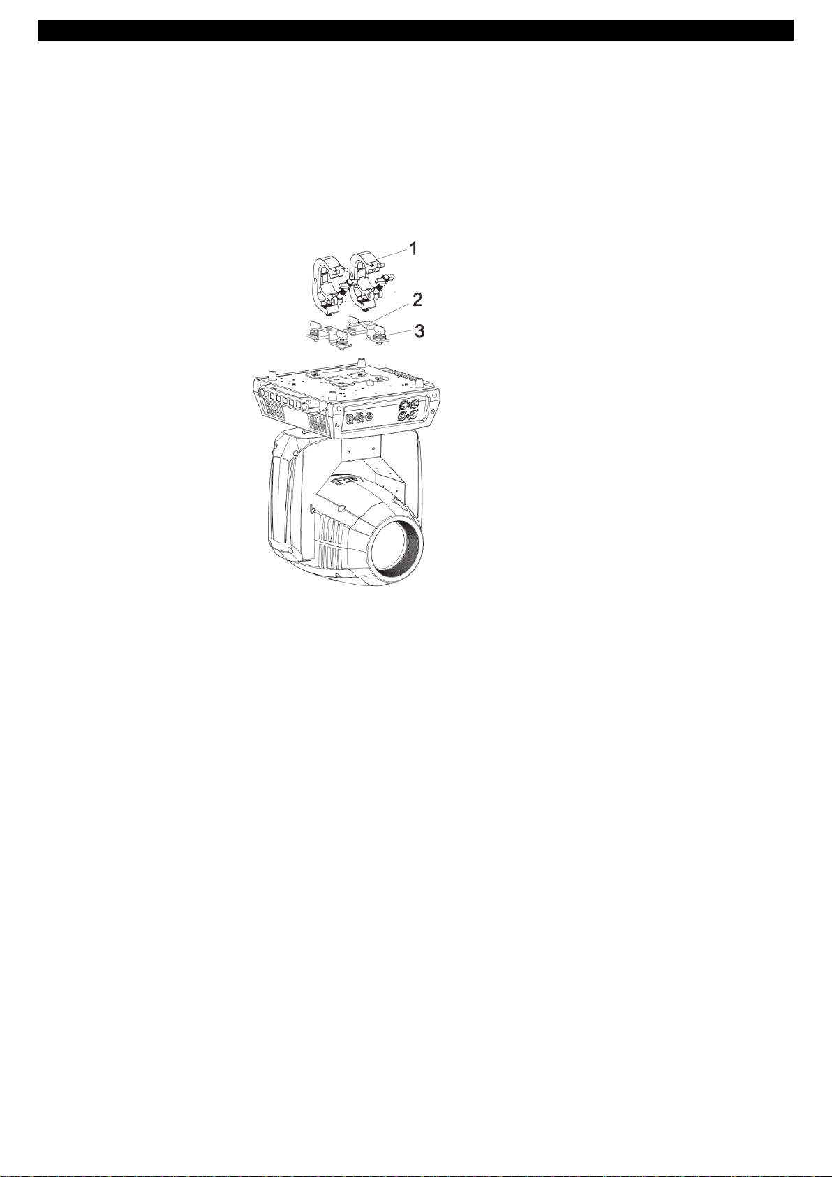
MOUNTING.............................................................................................................................................................................7
DMX SET UP ............................................................................................................................................................................9
DMX ADDRESSING ................................................................................................................................................................11
CONTROL PANEL AND CONNECTIONS..................................................................................................................................12
24 CHANNEL MODE (Basic Setting) ......................................................................................................................................13
26 CHANNEL MODE (Standard Setting) ................................................................................................................................17
38 CHANNEL MODE (Extended Setting) ...............................................................................................................................21
SYSTEM MENU......................................................................................................................................................................26
OPERATING INSTRUCTIONS..................................................................................................................................................27
WDMX (WIFLY) SET UP .........................................................................................................................................................31
OFFSET MENU.......................................................................................................................................................................31
ERROR CODES .......................................................................................................................................................................34
GOBO SPECIFICATIONS .........................................................................................................................................................35
GOBOS ..................................................................................................................................................................................36
CHANGING THE GOBO (1ST WHEEL) ....................................................................................................................................36
DIMMER CURVE CHART........................................................................................................................................................37
DIMENSIONAL DRAWING .....................................................................................................................................................37
MULTIPLE UNIT POWER LINKING .........................................................................................................................................38
FUSE REPLACEMENT .............................................................................................................................................................38
TROUBLE SHOOTING.............................................................................................................................................................38
CLEANING..............................................................................................................................................................................38
SPECIFICATIONS....................................................................................................................................................................38
ROHS - A great Contribution to the Conservation of Environment .....................................................................................39
WEEE –Waste of Electrical and Electronic Equipment ........................................................................................................39
NOTES ...................................................................................................................................................................................40

A.D.J. Supply Europe B.V. –www.adj.eu –Vizi CMY300 Instruction Manual Page 4
INOZIONE
INTRODUCTION
Unpacking: Thank you for purchasing the Vizi CMY300 by ADJ Products, LLC. Every Vizi CMY300 has been
thoroughly tested and has been shipped in perfect operating condition. Carefully check the shipping carton for
damage that may have occurred during shipping. If the carton appears to be damaged, carefully inspect your
fixture for any damage and be sure all accessories necessary to operate the unit has arrived intact. In the case
damage has been found or parts are missing, please contact our toll free customer support number for further
instructions. Do not return this unit to your dealer without first contacting customer support.
Introduction: The ADJ Vizi CMY300 is a DMX intelligent, high powered, CMY LED moving head fixture. To
optimize the performance of this product, please read these operating instructions carefully to familiarize
yourself with the basic operations of this unit. These instructions contain important safety information regarding
the use and maintenance of this unit. Please keep this manual with the unit, for future reference.
Customer Support: If you encounter any problems, please contact your trusted American Audio shop. We
also offer the possibility, to contact us directly: You can contact us via our website www.adj.eu or via email:
Warning! To prevent or reduce the risk of electrical shock or fire, do not expose this unit to rain or moisture.
Caution! There are no user serviceable parts inside this unit. Do not attempt any repairs yourself, doing so will
void your manufactures warranty. In the unlikely event your unit may require service please contact ADJ
Products, LLC.
PLEASE recycle the shipping carton when ever possible.
FEATURES
• Electronic Dimming 0-100%
• DMX-512 protocol
• 3-Pin and 5-Pin DMX Connection
• powerCON Input & Output
• Colors: 9 + Open (Including CTO 3200K & UV)
• GOBO Wheel 1: 7 Rotating/Replaceable + Open
GOBO Wheel 2: 9 Fixed + Open
• Prism 1: Rotating 3-facet Circular
• Prism 2: Rotating 6-facet Linear
• Linear Frost Effect
• Motorized Focus
• Motorized Zoom
• Three DMX Modes: 24 Channel Mode, 26 Channel Mode, and 38 Channel Mode.
• Multiple Unit Power Linking (See page 39)
INSTALLATION
The unit should be mounted using a mounting clamp (not provided), affixing it to the mounting bracket that is
provided with the unit. Always ensure that the unit is firmly fixed to avoid vibration and slipping while operating.
Always ensure that the structure to which you are attaching the unit is secure and is able to support a weight
of 10 times the unit’s weight. Also, always use a safety cable that can hold 12 times the weight of the unit
when installing the fixture.
The equipment must be installed by a professional, and it must be installed in a place where it is out of the
reach of people’s grasp.

A.D.J. Supply Europe B.V. –www.adj.eu –Vizi CMY300 Instruction Manual Page 5
SAFETY PRECAUTIONS
• To reduce the risk of electrical shock or fire, do not expose this unit rain or moisture
• Do not spill water or other liquids into or on to your unit.
• Do not attempt to operate this unit if the power cord has been frayed or broken. Do not attempt to remove or
break off the ground prong from the electrical cord. This prong is used to reduce the risk of electrical shock
and fire in case of an internal short.
• Disconnect from main power before making any type of connection.
• Do not remove the cover under any conditions. There are no user serviceable parts inside.
• Never operate this unit when it’s cover is removed.
• Never plug this unit in to a dimmer pack
• Always be sure to mount this unit in an area that will allow proper ventilation. Allow about 6” (15cm) between
this device and a wall.
• Do not attempt to operate this unit, if it becomes damaged.
• This unit is intended for indoor use only, use of this product outdoors voids all warranties.
• During long periods of non-use, disconnect the unit’s main power.
• Always mount this unit in safe and stable matter.
• Power-supply cords should be routed so that they are not likely to be walked on or pinched by items placed
upon or against them, paying particular attention to the point they exit from the unit.
• Cleaning -The fixture should be cleaned only as recommended by the manufacturer. See page 40 for
cleaning details.
• Heat -The appliance should be situated away from heat sources such as radiators, heat registers, stoves, or
other appliances (including amplifiers) that produce heat.
• The fixture should be serviced by qualified service personnel when:
A. The power-supply cord or the plug has been damaged.
B. Objects have fallen, or liquid has been spilled into the fixture.
C. The fixture has been exposed to rain or water.
D. The fixture does not appear to operate normally or exhibits a marked change in performance.
E. The fixture has fallen and/or subjected to extreme handling.

A.D.J. Supply Europe B.V. –www.adj.eu –Vizi CMY300 Instruction Manual Page 6
SAFETY PRECAUTIONS (continued)
RISK GROUP 3 - RISK OF EXPOSURE TO ULTRAVIOLET (UV) RADIATION!
FIXTURE EMITS HIGH INTENSITY ULTRAVIOLET (UV) LIGHT AT A WAVELENGTH OF 399NM - 435NM.
WEAR PROPER EYE AND SKIN PROTECTION.
AVOID PROLONGED PERIODS OF EXPOSURE.
AVOID WEARING WHITE COLOR CLOTHING AND/OR USING (UV) PAINTS ON SKIN.
AVOID DIRECT EYE AND/OR SKIN EXPOSURE AT DISTANCES SHORTER THAN 11 feet (3.3m).
DO NOT OPERATE FIXTURE WITH DAMAGED OR MISSING EXTERNAL COVER PROTECTIVE LENS.
DO NOT LOOK DIRECTLY INTO THE (UV) LIGHT AND/OR VIEW (UV) LIGHT DIRECTLY WITH OPTICAL
INSTRUMENTS THAT MAY CONCENTRATE THE LIGHT/RADIATION OUTPUT.
INDIVIDUALS SUFFERING FROM A RANGE OF EYE CONDITIONS, SUNLIGHT EXPOSURE
DISORDERS, OR INDIVIDUALS USING PHOTOSENSITIVE MEDICATION, MAY RECEIVE DISCOMFORT
IF EXPOSED TO THE ULTRAVIOLET (UV) LIGHT EMITTED FROM THIS FIXTURE.

A.D.J. Supply Europe B.V. –www.adj.eu –Vizi CMY300 Instruction Manual Page 7
MOUNTING
When installing the unit, the trussing or area of installation must be able to hold 10 times the weight without
any deformation. When installing the unit must be secured with a secondary safety attachment, e.g. and
appropriate safety cable. Never stand directly below the unit when mounting, removing, or servicing the unit.
Overhead mounting requires extensive experience, including calculating working load limits, installation
material being used, and periodic safety inspection of all installation material and unit. If you lack these
qualifications, do not attempt the installation yourself.
These installation should be checked by a skilled person once a year.
The Vizi CMY300 is fully operational in three different mounting positions, hanging upside-down from a ceiling,
sideways on trussing, or set on a flat level surface. Be sure this fixture is kept at least 12m (40ft) away from
any flammable materials (decoration etc.). Always use and install the supplied safety cable as a safety
measure to prevent accidental damage and/or injury in the event the clamp fails (see next page). Never use
the carrying handles for secondary attachment.

A.D.J. Supply Europe B.V. –www.adj.eu –Vizi CMY300 Instruction Manual Page 8
MOUNTING (continued)
NOTICE: The suitable environmental temperature for this lighting fixture is between -25˚ C to 45˚ C. Do not
place this lighting fixture in an environment where the temperatures are under or above the temperatures
stated above. This will allow the fixture to run at its best and help prolong the fixture life.
1. Bolt each clamp to the Omega holder with screw and lock nut through the hole in the holder.
2. Fasten the Omega holders on the bottom of the base by inserting quick-lock fasteners into the holes of the
base and tighten fully clockwise.
3. Hang the fixture to the support using the clamps and tighten the screws. Fasten a safety cable through the
bottom of the base and over the support.
Screw one clamp each via a M12 screw and nut into the Omega holders. Insert the quick-lock fasteners of the
Omega holder’s into the respective holes on the bottom of the Vizi CMY300. Tighten the quick-lock fasteners
fully clockwise. Install the second Omega holder. Pull the safety-cable through the openings located on the
base plate and over the trussing system or a safe fixation spot. Insert the end in the carabine and tighten the
safety screw.
1. Clamp
2. Omega-holders
3. Quick-lock fastener

A.D.J. Supply Europe B.V. –www.adj.eu –Vizi CMY300 Instruction Manual Page 9
DMX SET UP
Power Supply: The ADJ Vizi CMY300 contains an automatic voltage switch, which will auto sense the voltage
when it is plugged into the power source. With this switch there is no need to worry about the correct power
voltage, this unit can be plugged in anywhere.
DMX-512: DMX is short for Digital Multiplex. This is a universal protocol used as a form of communication
between intelligent fixtures and controllers. A DMX controller sends DMX data instructions from the controller
to the fixture. DMX data is sent as serial data that travels from fixture to fixture via the DATA “IN” and DATA
“OUT” XLR terminals located on all DMX fixtures (most controllers only have a DATA “OUT” terminal).
DMX Linking: DMX is a language allowing all makes and models of different manufactures to be linked
together and operate from a single controller, as long as all fixtures and the controller are DMX compliant. To
ensure proper DMX data transmission, when using several DMX fixtures try to use the shortest cable path
possible. The order in which fixtures are connected in a DMX line does not influence the DMX addressing. For
example; a fixture assigned a DMX address of 1 may be placed anywhere in a DMX line, at the beginning, at
the end, or anywhere in the middle. When a fixture is assigned a DMX address of 1, the DMX controller knows
to send DATA assigned to address 1 to that unit, no matter where it is located in the DMX chain.
Data Cable (DMX Cable) Requirements (For DMX Operation): The Vizi CMY300 can
be controlled via DMX-512 protocol. The Vizi CMY300 has 3 DMX channel modes. Your
unit and your DMX controller require a standard 3-pin XLR connector for data input and
data output (Figure 1). We recommend Accu-Cable DMX cables. If you are making your
own cables, be sure to use standard 110-120 Ohm shielded cable (This cable may be
purchased at almost all pro lighting stores). Your cables should be made with a male and
female XLR connector on either end of the cable. Also remember that DMX cable must be
daisy chained and cannot be split.
Notice: Be sure to follow figures two and three when making your own cables. Do not use the ground lug on
the XLR connector. Do not connect the cable’s shield conductor to the ground lug or allow the shield conductor
to come in contact with the XLR’s outer casing. Grounding the shield could cause a short circuit and erratic
behavior.
Figure 2
XLR Pin Configuration
Pin1 = Ground
Pin2 = Data Compliment (negative)
Pin3 = Data True (positive)
Figure 3
Figure 1

A.D.J. Supply Europe B.V. –www.adj.eu –Vizi CMY300 Instruction Manual Page 10
DMX SET UP (continued)
Special Note: Line Termination. When longer runs of cable are used, you may need to use a terminator on
the last unit to avoid erratic behavior. A terminator is a 110-120 ohm 1/4 watt resistor which is connected
between pins 2 and 3 of a male XLR connector (DATA + and DATA -). This unit is inserted in the female XLR
connector of the last unit in your daisy chain to terminate the line. Using a cable terminator (ADJ part number
Z-DMX/T) will decrease the possibilities of erratic behavior.
Termination reduces signal errors and avoids
signal transmission problems and interference.
It is always advisable to connect a DMX
terminal, (Resistance120 Ohm 1/4 W) between
PIN 2 (DMX-) and PIN 3 (DMX +) of the last
fixture.
Figure 4
5-Pin XLR DMX Connectors. Some manufactures use 5-pin DMX-512 data cables for DATA transmission in
place of 3-pin. 5-pin DMX fixtures may be implemented in a 3-pin DMX line. When inserting standard 5-pin
data cables in to a 3-pin line a cable adaptor must be used, these adaptors are readily available at most
electric stores. The chart below details a proper cable conversion.
3-Pin XLR to 5-Pin XLR Conversion
Conductor
3-pin XLR Female (Out)
5-pin XLR Male (In)
Ground/Shield
Pin 1
Pin 1
Data compliment (- signal)
Pin 2
Pin 2
Data True (+ signal)
Pin 3
Pin 3
Not used
Do Not Use
Not used
Do Not Use

A.D.J. Supply Europe B.V. –www.adj.eu –Vizi CMY300 Instruction Manual Page 11
DMX ADDRESSING
DMX ADDRESSING
All fixtures should be given a DMX starting address when using a DMX controller, so the correct fixture
responds to the correct control signal. This digital starting address is the channel number from which the
fixture starts to “listen” to the digital control signal sent out from the DMX controller. The assignment of this
starting DMX address is achieved by setting the correct DMX address on the digital control display on the
fixture.
You can set the same starting address for all fixtures or a group of fixtures, or set different addresses for each
individual fixture. Setting all fixtures to the same DMX address will cause all fixtures to react in the same way,
in other words, changing the settings of one channel will affect all the fixtures simultaneously.
If you set each fixture to a different DMX address, each unit will start to “listen” to the channel number you
have set, based on the quantity of DMX channels of each fixture. That means changing the settings of one
channel will only affect the selected fixture.
In the case of the Vizi CMY300, when in 24 Channel you should set the starting DMX address of the first unit
to 1, the second unit to 25 (24 + 1), the third unit to 49 (24 + 24 + 1), and so on. (See chart below for more
details.)
Channel Mode
Unit 1
Unit 2
Unit 3
Unit 4
Address
Address
Address
Address
24 channels
1
25
49
73
26 channels
1
27
53
79
38 channels
1
39
77
115

A.D.J. Supply Europe B.V. –www.adj.eu –Vizi CMY300 Instruction Manual Page 12
CONTROL PANEL AND CONNECTIONS
Front view Rear view
1. WiFly Antenna
2. Service Port: USB Slot is used to upgrade the unit firmware
3. LED:
POWER
On
Power On
DMX
On
DMX input present
4. Display: to show the various menus and the selected function.
5. Button:
MENU
To enter into the menu or leave the menu
UP
To move up in the menu
DOWN
To move down in the menu
ENTER
To perform the desired functions
6. DMX input/output: For DMX 512 operation, use 3/5 pin XLR plug cable to link the units together.
7. Fuse (T10A): Protect the unit from damage of over current.
8. Power Cable: To connect to the main power supply or next fixture.

A.D.J. Supply Europe B.V. –www.adj.eu –Vizi CMY300 Instruction Manual Page 13
24 CHANNEL MODE (Basic Setting)
1Channel
Value
Function
1
0 - 255
PAN MOVEMENT BY 540°
2
0 - 255
TILT MOVEMENT BY 270°
3
0 - 6
7 - 12
13 - 18
19 - 25
26 - 31
32 - 37
38 - 44
45 - 50
51 - 56
57 - 63
64 - 127
128 - 190
191 - 192
193 - 255
COLOR WHEEL
OPEN
RED
LIGHT GREEN
PINK
ORANGE
CTB
CTO
UV
GREEN
LIGHT BLUE
COLOR INDEXING
CLOCKWISE SCROLL FAST - SLOW
STOP
COUNTER-CLOCKWISE SCROLL SLOW - FAST
4
0 - 255
CYAN
0% - 100%
5
0 - 255
MAGENTA
0% - 100%
6
0 - 255
YELLOW
0% - 100%
7
0 - 7
8 - 15
16 - 23
24 - 31
32 - 39
40 - 47
48 - 55
56 - 63
64 - 72
73 - 81
82 - 90
91 - 99
100 - 108
109 - 117
118 - 127
128 - 190
191 - 192
193 - 255
ROTATING GOBOS (GOBO WHEEL 1)
OPEN
ROTATING GOBO 1
ROTATING GOBO 2
ROTATING GOBO 3
ROTATING GOBO 4
ROTATING GOBO 5
ROTATING GOBO 6
ROTATING GOBO 7
ROTATING GOBO 1 SHAKE
ROTATING GOBO 2 SHAKE
ROTATING GOBO 3 SHAKE
ROTATING GOBO 4 SHAKE
ROTATING GOBO 5 SHAKE
ROTATING GOBO 6 SHAKE
ROTATING GOBO 7 SHAKE
CLOCKWISE SCROLL FAST - SLOW
STOP
COUNTER-CLOCKWISE SCROLL SLOW - FAST
8
0 - 127
128 - 190
191 - 192
193 - 255
ROTATING GOBO INDEXING & GOBO ROTATION
GOBO INDEXING 0 - 360
CLOCKWISE ROTATION FAST - SLOW
STOP
COUNTER-CLOCKWISE ROTATION SLOW - FAST

A.D.J. Supply Europe B.V. –www.adj.eu –Vizi CMY300 Instruction Manual Page 14
24 CHANNEL MODE (Basic Setting) (continued)
1Channel
Value
Function
9
0 - 6
7 - 12
13 - 18
19 - 25
26 - 31
32 - 37
38 - 44
45 - 50
51 - 56
57 - 63
64 - 70
71 - 77
78 - 84
85 - 91
92 - 98
99 - 105
106 - 112
113 - 119
120 - 127
128 - 190
191 - 192
193 - 255
FIXED GOBOS (GOBO WHEEL 2)
OPEN
GOBO 1
GOBO 2
GOBO 3
GOBO 4
GOBO 5
GOBO 6
GOBO 7
GOBO 8
GOBO 9
GOBO 1 SHAKE SLOW –FAST
GOBO 2 SHAKE SLOW –FAST
GOBO 3 SHAKE SLOW –FAST
GOBO 4 SHAKE SLOW –FAST
GOBO 5 SHAKE SLOW –FAST
GOBO 6 SHAKE SLOW –FAST
GOBO 7 SHAKE SLOW –FAST
GOBO 8 SHAKE SLOW –FAST
GOBO 9 SHAKE SLOW –FAST
CLOCKWISE WHEEL ROTATION FAST - SLOW
STOP
COUNTER-CLOCKWISE WHEEL ROTATION SLOW - FAST
10
0 - 10
11 - 127
128 - 255
PRISM 1 (LINEAR)
NO EFFECT
ON
MACRO 1 - 32
11
0 - 127
128 - 190
191 - 192
193 - 255
PRISM 1 ROTATION
PRISM INDEXING
CLOCKWISE ROTATION FAST - SLOW
NO ROTATION
COUNTER-CLOCKWISE ROTATION SLOW - FAST
12
0 - 127
128 - 255
PRISM 2 (3 FACET)
NO EFFECT
ON
13
0 - 127
128 - 190
191 - 192
193 - 255
PRISM 2 ROTATION
PRISM INDEXING
CLOCKWISE ROTATION FAST - SLOW
NO ROTATION
COUNTER-CLOCKWISE ROTATION SLOW - FAST
14
0 - 255
FOCUS
CONTINUOUS ADJUSTMENT FROM NEAR - FAR
15
0 - 255
ZOOM
ZOOM ADJUSTMENT FROM SMALL - BIG
16
0 - 31
32 - 63
64 - 95
96 - 127
128 - 159
160 - 191
192 - 223
224 - 255
SHUTTER & STROBE
SHUTTER CLOSED
SHUTTER OPEN
STROBE EFFECT SLOW - FAST
SHUTTER OPEN
PULSE EFFECT
SHUTTER OPEN
RANDOM STROBE EFFECT SLOW - FAST
SHUTTER OPEN
17
0 - 255
MASTER DIMMER
0% - 100%

A.D.J. Supply Europe B.V. –www.adj.eu –Vizi CMY300 Instruction Manual Page 15
24 CHANNEL MODE (Basic Setting) (continued)
1Channel
Value
Function
18
0 - 191
192 - 223
224 - 255
IRIS
MAXIMUM DIAMETER TO MINIMUM DIAMETER
PULSE CLOSING FAST - SLOW
PULSE OPENING SLOW - FAST
19
0 - 255
FROST
0% - 100%
20
0 - 255
CMY SPEED & COLOR MACRO SPEED
FAST - SLOW
21
PAN/TILT MOVEMENT SPEED
FAST –SLOW
22
0 - 7
8 - 15
16 - 23
24 - 31
32 - 39
40 - 47
48 - 55
56 - 63
64 - 71
72 - 79
80 - 87
88 - 95
96 - 103
104 - 111
112 - 119
120 - 127
128 - 135
136 - 143
144 - 151
152 - 159
160 - 167
168 - 175
176 - 183
184 - 191
192 - 199
200 - 207
208 - 215
216 - 223
224 - 231
232 - 239
240 - 247
248 - 255
COLOR MACRO
OFF
MACRO 1
MACRO 2
MACRO 3
MACRO 4
MACRO 5
MACRO 6
MACRO 7
MACRO 8
MACRO 9
MACRO 10
MACRO 11
MACRO 12
MACRO 13
MACRO 14
MACRO 15
MACRO 16
MACRO 17
MACRO 18
MACRO 19
MACRO 20
MACRO 21
MACRO 22
MACRO 23
MACRO 24
MACRO 25
MACRO 26
MACRO 27
MACRO 28
MACRO 29
MACRO 30
RANDOM CMY
23
0 - 20
21 - 40
41 - 60
61 - 80
81 - 100
101 - 255
DIMMER MODES
STANDARD
STAGE
TV
ARCHITECTURAL
THEATER
DEFAULT TO UNIT SETTING

A.D.J. Supply Europe B.V. –www.adj.eu –Vizi CMY300 Instruction Manual Page 16
24 CHANNEL MODE (Basic Setting) (continued)
1Channel
Value
Function
24
0 - 69
70 - 79
80 - 89
90 - 99
100 - 109
110 - 119
120 - 129
130 - 139
140 - 149
150 - 159
160 - 169
170 - 199
200 - 209
210 - 219
220 - 229
230 - 255
SPECIAL FUNCTIONS
NOTHING
ENABLE BLACKOUT WITH PAN/TILT MOVEMENT
DISABLE BLACKOUT WITH PAN/TILT MOVEMENT
ENABLE BLACKOUT WITH COLOR WHEEL MOVEMENT
DISABLE BLACKOUT WITH COLOR WHEEL MOVEMENT
ENABLE BLACKOUT WITH GOBO WHEEL MOVEMENT
DISABLE BLACKOUT WITH GOBO WHEEL MOVEMENT
FOCUS COMPENSATE DISABLE
FOCUS COMPENSATE NEAR
FOCUS COMPENSATE MEDIUM
FOCUS COMPENSATE FAR
NOTHING
RESET ALL
RESET EFFECT
RESET PAN/TILT MOTORS
NOTHING

A.D.J. Supply Europe B.V. –www.adj.eu –Vizi CMY300 Instruction Manual Page 17
26 CHANNEL MODE (Standard Setting)
1Channel
Value
Function
1
0 - 255
PAN MOVEMENT BY 540°
2
PAN MOVEMENT FINE (16BIT)
3
0 - 255
TILT MOVEMENT BY 270°
4
0 - 255
TILT MOVEMENT FINE (16BIT)
5
0 - 6
7 - 12
13 - 18
19 - 25
26 - 31
32 - 37
38 - 44
45 - 50
51 - 56
57 - 63
64 - 127
128 - 190
191 - 192
193 - 255
COLOR WHEEL
OPEN
RED
LIGHT GREEN
PINK
ORANGE
CTB
CTO
UV
GREEN
LIGHT BLUE
COLOR INDEXING
CLOCKWISE SCROLL FAST - SLOW
STOP
COUNTER-CLOCKWISE SCROLL SLOW - FAST
6
0 - 255
CYAN
0% - 100%
7
0 - 255
MAGENTA
0% - 100%
8
0 - 255
YELLOW
0% - 100%
9
0 - 7
8 - 15
16 - 23
24 - 31
32 - 39
40 - 47
48 - 55
56 - 63
64 - 72
73 - 81
82 - 90
91 - 99
100 - 108
109 - 117
118 - 127
128 - 190
191 - 192
193 - 255
ROTATING GOBOS (GOBO WHEEL 1)
OPEN
ROTATING GOBO 1
ROTATING GOBO 2
ROTATING GOBO 3
ROTATING GOBO 4
ROTATING GOBO 5
ROTATING GOBO 6
ROTATING GOBO 7
ROTATING GOBO 1 SHAKE
ROTATING GOBO 2 SHAKE
ROTATING GOBO 3 SHAKE
ROTATING GOBO 4 SHAKE
ROTATING GOBO 5 SHAKE
ROTATING GOBO 6 SHAKE
ROTATING GOBO 7 SHAKE
CLOCKWISE SCROLL FAST - SLOW
STOP
COUNTER-CLOCKWISE SCROLL SLOW - FAST
10
0 - 127
128 - 190
191 - 192
193 - 255
ROTATING GOBO INDEXING & GOBO ROTATION
GOBO INDEXING 0 - 360
CLOCKWISE ROTATION FAST - SLOW
STOP
COUNTER-CLOCKWISE ROTATION SLOW - FAST

A.D.J. Supply Europe B.V. –www.adj.eu –Vizi CMY300 Instruction Manual Page 18
26 CHANNEL MODE (Standard Setting) (continued)
1Channel
Value
Function
11
0 - 6
7 - 12
13 - 18
19 - 25
26 - 31
32 - 37
38 - 44
45 - 50
51 - 56
57 - 63
64 - 70
71 - 77
78 - 84
85 - 91
92 - 98
99 - 105
106 - 112
113 - 119
120 - 127
128 - 190
191 - 192
193 - 255
FIXED GOBOS (GOBO WHEEL 2)
OPEN
GOBO 1
GOBO 2
GOBO 3
GOBO 4
GOBO 5
GOBO 6
GOBO 7
GOBO 8
GOBO 9
GOBO 1 SHAKE SLOW –FAST
GOBO 2 SHAKE SLOW –FAST
GOBO 3 SHAKE SLOW –FAST
GOBO 4 SHAKE SLOW –FAST
GOBO 5 SHAKE SLOW –FAST
GOBO 6 SHAKE SLOW –FAST
GOBO 7 SHAKE SLOW –FAST
GOBO 8 SHAKE SLOW –FAST
GOBO 9 SHAKE SLOW –FAST
CLOCKWISE WHEEL ROTATION FAST - SLOW
STOP
COUNTER-CLOCKWISE WHEEL ROTATION SLOW - FAST
12
0 - 10
11 - 127
128 - 255
PRISM 1 (LINEAR)
NO EFFECT
ON
MACRO 1 - 32
13
0 - 127
128 - 190
191 - 192
193 - 255
PRISM 1 ROTATION
PRISM INDEXING
CLOCKWISE ROTATION FAST - SLOW
NO ROTATION
COUNTER-CLOCKWISE ROTATION SLOW - FAST
14
0 - 127
128 - 255
PRISM 2 (3 FACET)
NO EFFECT
ON
15
0 - 127
128 - 190
191 - 192
193 - 255
PRISM 2 ROTATION
PRISM INDEXING
CLOCKWISE ROTATION FAST - SLOW
NO ROTATION
COUNTER-CLOCKWISE ROTATION SLOW - FAST
16
0 - 255
FOCUS
CONTINUOUS ADJUSTMENT FROM NEAR - FAR
17
0 - 255
ZOOM
ZOOM ADJUSTMENT FROM SMALL - BIG
18
0 - 31
32 - 63
64 - 95
96 - 127
128 - 159
160 - 191
192 - 223
224 - 255
SHUTTER & STROBE
SHUTTER CLOSED
SHUTTER OPEN
STROBE EFFECT SLOW - FAST
SHUTTER OPEN
PULSE EFFECT
SHUTTER OPEN
RANDOM STROBE EFFECT SLOW - FAST
SHUTTER OPEN
19
0 - 255
MASTER DIMMER
0% - 100%

A.D.J. Supply Europe B.V. –www.adj.eu –Vizi CMY300 Instruction Manual Page 19
26 CHANNEL MODE (Standard Setting) (continued)
1Channel
Value
Function
20
0 - 191
192 - 223
224 - 255
IRIS
MAXIMUM DIAMETER TO MINIMUM DIAMETER
PULSE CLOSING FAST - SLOW
PULSE OPENING SLOW - FAST
21
0 - 255
FROST
0% - 100%
22
0 - 255
CMY SPEED & COLOR MACRO SPEED
FAST - SLOW
23
PAN/TILT MOVEMENT SPEED
FAST –SLOW
24
0 - 7
8 - 15
16 - 23
24 - 31
32 - 39
40 - 47
48 - 55
56 - 63
64 - 71
72 - 79
80 - 87
88 - 95
96 - 103
104 - 111
112 - 119
120 - 127
128 - 135
136 - 143
144 - 151
152 - 159
160 - 167
168 - 175
176 - 183
184 - 191
192 - 199
200 - 207
208 - 215
216 - 223
224 - 231
232 - 239
240 - 247
248 - 255
COLOR MACRO
OFF
MACRO 1
MACRO 2
MACRO 3
MACRO 4
MACRO 5
MACRO 6
MACRO 7
MACRO 8
MACRO 9
MACRO 10
MACRO 11
MACRO 12
MACRO 13
MACRO 14
MACRO 15
MACRO 16
MACRO 17
MACRO 18
MACRO 19
MACRO 20
MACRO 21
MACRO 22
MACRO 23
MACRO 24
MACRO 25
MACRO 26
MACRO 27
MACRO 28
MACRO 29
MACRO 30
RANDOM CMY
25
0 - 20
21 - 40
41 - 60
61 - 80
81 - 100
101 - 255
DIMMER MODES
STANDARD
STAGE
TV
ARCHITECTURAL
THEATER
DEFAULT TO UNIT SETTING

A.D.J. Supply Europe B.V. –www.adj.eu –Vizi CMY300 Instruction Manual Page 20
26 CHANNEL MODE (Standard Setting) (continued)
1Channel
Value
Function
26
0 - 69
70 - 79
80 - 89
90 - 99
100 - 109
110 - 119
120 - 129
130 - 139
140 - 149
150 - 159
160 - 169
170 - 199
200 - 209
210 - 219
220 - 229
230 - 255
SPECIAL FUNCTIONS
NOTHING
ENABLE BLACKOUT WITH PAN/TILT MOVEMENT
DISABLE BLACKOUT WITH PAN/TILT MOVEMENT
ENABLE BLACKOUT WITH COLOR WHEEL MOVEMENT
DISABLE BLACKOUT WITH COLOR WHEEL MOVEMENT
ENABLE BLACKOUT WITH GOBO WHEEL MOVEMENT
DISABLE BLACKOUT WITH GOBO WHEEL MOVEMENT
FOCUS COMPENSATE DISABLE
FOCUS COMPENSATE NEAR
FOCUS COMPENSATE MEDIUM
FOCUS COMPENSATE FAR
NOTHING
RESET ALL
RESET EFFECT
RESET PAN/TILT MOTORS
NOTHING
Other manuals for VIZI CMY300
2
Table of contents
Other ADJ Dj Equipment manuals

ADJ
ADJ 32 HEX PANEL IP User manual

ADJ
ADJ PAR Z120 RGBW User manual

ADJ
ADJ ENCORE LP12Z IP User manual

ADJ
ADJ POCKET PRO User manual

ADJ
ADJ 1226100361 User manual

ADJ
ADJ ENTOUR ICE User manual

ADJ
ADJ Focus Spot Three Z User manual

ADJ
ADJ MOD TW100 User manual

ADJ
ADJ Royal 3D User manual

ADJ
ADJ NINJA 5RX User manual

ADJ
ADJ WiFly Chameleon User manual

ADJ
ADJ 18P HEX IP User manual

ADJ
ADJ Inno Pocket Spot Pearl User manual

ADJ
ADJ Vizi BSW 300 User manual

ADJ
ADJ 32 HEX PANEL IP User manual

ADJ
ADJ FOCUS BEAM LED User manual

ADJ
ADJ MEGA HEX PAR User manual

ADJ
ADJ VIZI CMY300 User manual

ADJ
ADJ VIZ870 User manual

ADJ
ADJ M-1212 User manual