Adjust-a-Sink K100 Series User manual

1 of 11
Adjust-a-Sink
£
££
£
K100 SERIES
**INSTALLATION INSTRUCTIONS**
10/2011
Congratulations on the purchase of your new Adjust-a-Sink
®
System-the elevating sink that
offers the ultimate in comfort and safety. The Adjust-a-Sink
®
System utilizes a unique hydraulic lift
mechanism and a UPC listed, patented 3-stage telescoping plumbing unit* that allows the operator to
raise and lower the shampoo bowl a total of 12” simply by pumping the convenient foot pedal. This
foot pedal can also be rotated to the side, providing the stylist an unobstructed work area when
needed.
The Adjust-a-Sink
®
System was designed with simplicity and long lasting durability in mind. The lift
system, cultured marble shampoo bowl, laminated panels and chrome plated pump make the entire
system easy to clean and virtually maintenance free.
IMPORTANT: Please read through all these instruction sheets and become familiar with all the
parts and requirements PRIOR to installation. Although the system can be installed in most
work areas with the proper water and waste connections, there are necessary steps that are
very important to follow to ensure the proper operation of the Adjust-a-Sink®. Refer to the
appropriate local and state codes as it applies to the location of the waste drain and use of a
hair trap (interceptor) for your particular installation.
The following Step-by-Step Instructions reference the following Accessible Systems drawings:
K100 Overall Assembly, Sheet 1
K100 Overall Assembly, Sheet 2
K100-87 Plumbing Rough-In Drawing
Required Hardware/Supplies Not Included: 1 ½” White PVC UPC Listed P-Trap, ½” ID Rigid
Copper Tubing, 90 Degree Supply line shut-off valves, Long-Length Sheet Rock Screws, 5/16” Bolts-
Washers-Nuts (if mounting to cabinet), Plumbing Supplies such as Plumbers Putty, Sealant, Silicone
Caulk, etc.
Thank you for purchasing the Adjust-a-Sink®. For replacement part orders or further
information please contact Customer Service at: Accessible Systems LLC - 2940 Weeks Ave
S.E. Minneapolis MN 55414
Local Building Codes May Apply. Adjust-a-Sink® is a registered trademark of Accessible Systems, LLC
*Patent Numbers 5,893,396 5,867,847

2 of 11
STEP 1: SITE EVALUATION, PLUMBING ROUGH IN, and MOUNTING PANEL
PREPARATION.
The Adjust-a-Sink
®
System is designed to be mounted directly to the face of a finished interior wall,
with the proper rough-in plumbing already installed. The System can also be cabinet or station
mounted by a qualified installer.
INSTALLERS, PLEASE NOTE:
If the Adjust-a-Sink
®
unit is to be mounted on a cabinet face or a shampoo station,
it is extremely important that the cabinetry counter top or ledge be FLUSH and SQUARE
BEHIND the Adjust-a-Sink Wall Mounting Panel. There must be NO counter top lip
or ledge overhanging the Wall Mounting Panel, as it will interfere with the sink action as it
elevates, causing possible damage to both the Adjust-a-Sink and surrounding cabinetry.
Please allow 6-12” on either side of the unit for clearance and stylist work space! Accessible
Systems, LLC will not be liable for injury or damages caused by improper installation.
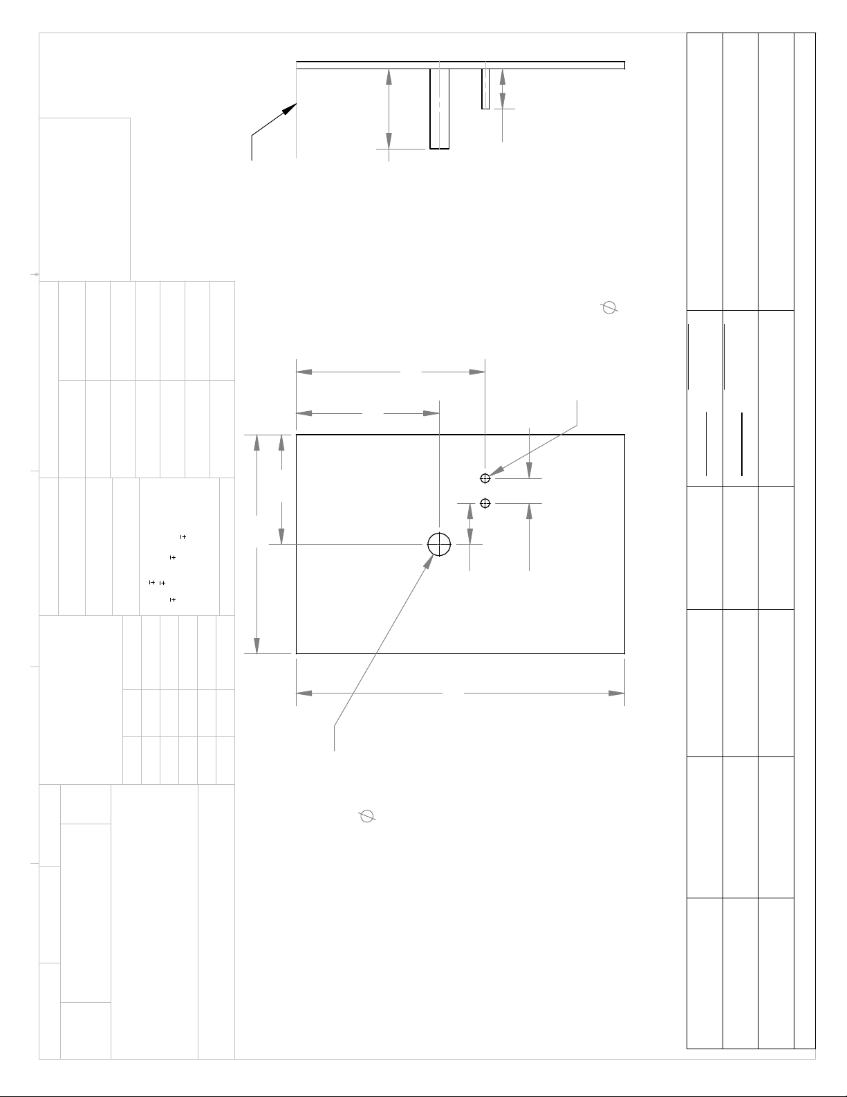
Referring to drawing K100-87 Plumbing Rough-In, note that the Wall Mounting Panel is 22” wide and
33” High. The bottom of the Wall Mounting Panel rests on the finished floor. The installer should
verify that there is sufficient space to mount this panel, also keeping in mind that the Lift Backsplash
itself will elevate an additional 12” in height.
The mounted shampoo bowl and its drain is centered within the 22” width of the Wall Mounting Panel
that is, the center of the drain is 11” from the left edge. Keeping this in mind will simplify the process.
Recommended and best rough-in plumbing hardware and locations are as follows:
Waste Water Drain Pipe:
1-1/2” ID white PVC: Locate pipe center 11” from the left edge of the Wall Mounting
Panel.
Refer to “Rough In” Drawing K100-87 for the recommended height
for the waste drain. Stub out 8” minimum from finished wall. (Exact
length will be determined at final plumbing.)
IMPORTANT NOTES:
UPC Listed P-Trap Must Be Used! Please reference Drawing K100-87 for the acceptable water
line locations (for both waste and supply lines).
The building drain MUST BE stubbed out of the wall (about 8” out) on the exact center of the
unit from left to right. (It may be useful to delay gluing the stub into the wall until making the
final hook up).
If using a Hair Trap refer to Drawing K100-87 for waste drain “rough in” dimension, ensure
there is enough space under the trap to enable you to remove and clean filter (#8750 model).

3 of 11
Water Supply Lines:
1/2” ID rigid copper tube: HOT: Refer to Drawing K100-87 for the Location of the Water Lines
COLD: Refer to Drawing K100-87 for the Location of the Water Lines
Stub out 4” from the finished wall.
IMPORTANT: Since many installations may not be able to locate the plumbing rough in exactly
as specified, refer to Drawing K100-87 Plumbing “Rough-In” for the allowable areas plumbing
may penetrate the Wall Mounting Panel. Caution! Plumbing falling outside this area may
cause interference problems with moving sink components. Other plumbing drain/water
configurations such as rough in through the floor are permissible; however the installation
becomes the responsibility of the installer.
1B: Drilling/Hole Cutting the necessary holes in the Mounting Panel for water supply lines and
Drain Pipe: Unpack the Wall Mounting Panel along with the Lift Backsplash. Mark the hole
locations on the Mounting Panel per the dimensions that correspond to where the water supply lines
and drains are located on the wall (or sturdy cabinet) on which it will mount. Before you begin, verify
once more that the wastewater drain pipe and supply water stub-outs have been properly located per
drawing K100-87 Plumbing Rough-In. We suggest that you use the following to drill out the
necessary through holes on the mounting panel:
7/8” Min. Dia. – Hot, Cold Water Lines
2 1/4” Min. Dia. Hole Saw – Waste Drain

4 of 11
STEP 2: WALL MOUNTING PANEL INSTALLATION
2A.Carefully unpack the balance of the Adjust-a-Sink® System and verify all components are
included and undamaged. The Adjust-a-Sink® System comes with most of its components already
assembled.
2B. Install the shampoo bowl Sink Mounting Bracket and the Lift Backsplash with the hardware
provided. (Use the proper size screws and quantities as required; lock washers and nuts go on the
backside of the Lift Panel.) NOTE: The Lift Panel is predrilled with the proper number of holes and
spacing for either the Marble Products 3000W or Belvedere 8400 Shampoo Bowl.
Due to its metal components and sturdy construction, the assembled Adjust-a-Sink
®
is quite heavy.
Because of this, and to ensure proper operation, it is recommended to locate wall-framing studs
behind the finished wall and then fasten the Wall Mounting Panel to the studs using multiple, long
length sheet rock screws (not supplied). In some installations where framing members may fall
outside the Wall Mounting Panel, apply a generous amount of construction adhesive (not supplied)
around the entire back of the panel and secure it to the wall that way. Consult adhesive instructions
for proper conditions and restrictions.
If your Wall Mounting Panel requires a different installation arrangement, it is the installer’s
responsibility to calculate, verify and drill the panel according to the guidelines already established.
Again, review drawing K100-87 Plumbing Rough-In for details.
IMPORTANT: When securing the unit to a sturdy cabinet, we suggest that you use (4) 5/16”
bolts of the appropriate length with (2) 5/16” fender washers, and 1 lock washer and nut per
bolt. Space these (4) bolts in a manner that provides maximum support and affords coverage
by the Shroud so that bolts are not visible post installation.
2C.Once the Wall Mounting Panel is positively secured to the wall, align the hydraulic lift Floor Plate
by adjusting the two socket-set screws hidden beneath the Retainer Ring. See item # 2 on drawing
K100 sheet 2.
Remove the six #10-24 pan head screws as indicated but do not discard. Using a 5/32 hex key, turn
the two screws equally clockwise: the requirement is to make the Floor Plate perpendicular to the
Wall Mounting Plate. Using a small carpenter’s square, place one edge up against the Wall
Mounting Panel and gauge according. When perpendicular, reinstall the six #10-24 pan head
screws. Apply a bead of silicone based caulking (not supplied) all around the base of the Lift Plate at
the floor; this will keep water and other grime from collecting underneath. Additionally, seal all along
the Wall Mounting Plate bottom edge, where it rests on the floor.

5 of 11
STEP 3: FINISH PLUMBING
3A. Finish the supply water line installation. For both the Hot and Cold, use 1/2” x 3/8” (copper tube
OD x ID) 90-degree Angle Compression Water Supply Shutoffs and Trim Bezels. (Not Supplied).
3B.Shampoo Bowl: Install the faucet, hose and all related pieces to the shampoo bowl per the
instructions provided from the manufacturer. IMPORTANT: Be sure to use the Mainline Strainer
Basket provided from Adjust-a-Sink when using a MP3000W bowl – the basket can be installed with
or without the rubber gasket. When using a Belvedere bowl, use the bowl manufacturer’s basket
strainer. Use plumber’s putty when installing the basket strainer.
3C.Mount the shampoo bowl on the Sink Mounting Bracket. Be sure to level the sink to the Lift
Backsplash, secure its position using the leveling setscrew under the sink and properly secure it by
tightening the nut under each side of the bowl.
3D.Pump the hydraulic lift and elevate the shampoo bowl to its highest position. Mount the Drain
Pipe Support Bracket assembly onto the laminated mounting panel using the four 5/16” x ¾” bolts
provided. Mount the Drain Pipe Support Bracket by fastening the bolts into the four corresponding
threaded nuts. Refer to Drawing K100 for the proper bracket positioning. Make sure the two 5/16”
bolts holding the Drain Pipe Clamp to the Drain Pipe Support Bracket and the hose clamp are just
loose enough to make adjustments.
3E.With the shampoo bowl still at its highest position extend the Telescoping drain to the basket
strainer. Connect the slip joint nut to the basket strainer; make sure to use the nylon gasket provided
with the basket strainer. Make sure the drain cables face towards the wall-mounting panel at
this time. Adjust the bowl to ensure the drain parallel to the lift panel (perpendicular to the floor) by
adjusting the leveling setscrew under the shampoo bowl.
IMPORTANT: It is critical to the proper operation of the telescopic drain that the telescopic
drain is installed perpendicular to the floor – any deviation to this will cause premature wear
and possible failure of the drain system. Now move the unit to the lowest position and tighten the
two 5/16” bolts holding the pipe clamp to the drain support bracket making sure the drain is still
parallel. Also make sure the bracket is flush with the backside of the bottom section of drain before
tightening. Now move the unit to the upper most position. Move the bottom section of the drain unit
(2” PVC pipe) up about ¼” and tighten the hose clamp. Move the unit to both up & down extremes to
check for binding. Make any minor adjustments to eliminate any binding before proceeding.
IMPORTANT: Refer to pictures on pages 7 and 8 for drain positioning and orientation. Do not
construct your P-Trap until the drain is positioned properly and functions properly – as a
REFERENCE dimension, the distance from the bottom of the 2”x1½” reducer/coupling to the
floor should be approximately 15”.
CAUTION: Do not over tighten the hose clamp to the Drain Pipe Subassembly (#14). Lower the
shampoo bowl and observe the action. Again, movement of the Riser Pipe should be smooth and
continuous.

6 of 11
The shampoo bowl is shipped directly from the manufacturer. It is possible that there may be
slight variations in bowls. If the 3-Stage Telescoping Drain system IS NOT adjusted properly
at installation, damage or breakage of the drain system may result - We have attached the
bracket on the 3-Stage Telescoping Drain system, but it must be properly adjusted during
installation.
IMPORTANT: Do not trim or alter the Telescopic Drain in any way. All components that make
up the Telescopic Drain Pipe Subassembly are integrated and work together. Altering its
design will cause premature if not total failure of the telescopic drain mechanism.
3F. Now connect the bottom of the Drain Pipe Subassembly to the wastewater drain pipe using a
UPC approved PVC P-Trap (not supplied). Use appropriate plumbing methods to seal and secure
the P-trap to the drain and the roughed in 1 ½” waste drain. Do not glue the P-Trap until you
conduct the Initial Testing Procedure noted below.
Keep in mind that the Riser Pipe telescopes up and down within the Drain Pipe Subassembly.
Consider proper alignment when performing the final connection of the P-Trap to the Drain Pipe
Subassembly and wastewater drainpipe. The Riser Pipe cannot be allowed to bind; the motion
should be smooth and continuous. After P-Trap installation and proper alignment and smooth
action are achieved, connect the Riser Pipe to the basket strainer and tighten all associated
hardware. Care should be used so as to not cross thread the riser pipe nut onto the basket
strainer threads – make sure the brass screws on the drain are in alignment on each side of
the drain after the riser pipe nut has been tightened onto the basket strainer – see picture on
page 8 (lower left).
INITIAL TESTING PROCEDURE
•
Raise and lower the unit all the way up and down several times to be sure it is operating properly,
without binding before and after connecting it to the building drain.
•
IMPORTANT: Be sure there is about ¼” total slack in the cable linkage system when the
unit is fully extended as described above. It is important that the lift system limits out prior
to the drain extending to its full range. Make any minor adjustments that are needed to
keep the lift system from binding and to ensure that the lift system limits out prior to the 3-
Stage Telescopic Drain Assembly extending to its full range. See photos on pages 7 and 8.
• Now ensure that all of the parts are tightened securely and glue the 2” x 1½” PVC Reducer/
Coupling to the P-trap and wall drain. Care should be used to ensure you do NOT cause strain
or binding on the vertical 3-Stage Telescoping Drain Assembly.
3G.Connect the provided flexible Water Supply Lines to both the faucet and the water supply
shutoffs. Use care and good judgment when installing the flexible lines so they are free and
unobstructed when traveling with the elevating shampoo bowl.

7 of 11
FINAL TESTING/LEAK TESTING PROCEDURE
Turn on the faucet and let run for 3-5 minutes at both the highest and lowest height positions. Check
all assembled plumbing joints to verify seals. Take appropriate action to address any leaks. The
telescopic drains are pressure tested per ASME standards and date coded prior to shipment–they
should not leak if installed properly.
STEP 4. SHROUD INSTALLATION
With all the plumbing connected and operating smoothly, and prior to installing the Shroud, observe
that the Hydraulic Lift is also operating smoothly by raising and lowering the Shampoo Bowl. The Lift
Shafts should glide smoothly between the polyethylene Lift Guides. No further adjustments or
maintenance should be required.
Lower the unit to the lowest position. Attach the Shroud by hanging the shroud on the single stud on
the right side of the lift panel. Hand tighten the nylon nut to the stud. Loosen the three nylon cap
screws on the left lift shaft just enough to slide the shroud in between the head of the cap screw/o-
ring and the three flat washers. Tighten the top screw first. Once the top screw is tight, raise the unit
up to provide enough room to tighten the bottom two screws. Now go back to the nut on the other
side and tighten it. Securely tighten the cap screws with an Allen wrench. Ensure that there is no
interference between the left side of the shroud and the plastic lift guides. If there is, loosen
the top left nut and re-position the shroud so that it does not come in contact with the lift
guide.
INSTALLATION REFERENCE PHOTOS:
Note: Ensure there is clearance between the elevating
backsplash and the counter top lip
Note: The lift system limits prior to the drain
limiting out – both in the up and down
positions
Note Clearance Limited
Not limited

8 of 11
Note: Model shown utilizes side-mounting bracket. Depending upon the height
of your waste drain your model will utilize either a side or back mount bracket.
Model shown has hot/cold shut-off valves inside of cabinet.
Note: Ensure drain is level – perpendicular to floor Note: Nut for adjusting the sink angle
Note: The lift system limits out prior to the
drain limiting out, the drain is
perpendicular to the floor, and the
cables face the wall
Ad
j
ustment nu
t
Ensure
level
Fully Assembled Unit – In Up Position

9 of 11
MAINTENANCE FOR K-100 Adjust-A-Sink®
BASIC FEATURES: The Adjust-a-Sink
®
System elevates the Shampoo Bowl a total of 12”. Distance
from the floor to the top the of bowl ranges from approximately 34” to 46”. A self contained,
maintenance free foot-operated hydraulic lift provides the lift capacity needed to raise the shampoo
bowl. The hydraulic lift’s foot pedal is free to rotate approximately 90 degrees to the side anytime the
operator requires. Components are manufactured from the highest-grade materials and should
provide years of trouble-free service.
The “Adjust-a-Sink”®warranty is two (2) years on all parts and five (5) years on the hydraulic pump.
Altering the 3-Stage Telescopic Drain in any way voids its warranty.
Save these installation instructions for future reference.
IT IS VERY IMPORTANT TO HAVE THE “ADJUST-A-SINK”® INSTALLED CORRECTLY AND
THE PLUMBING ALIGNED PERFECTLY. NOT DOING SO COULD RESULT IN UNDUE
PRESSURE ON VARIOUS COMPONENT PARTS AND COULD ALSO CAUSE THE PLUMBING
TO LEAK.
Lubrication: When the sink will not be in use for a period of time, or over night, lower the sink to its
lowest position. This allows the shaft to stay lubricated in the hydraulic fluid. By doing this, it will
maintain the smoothness of the elevation. NOTE: We recommend that you raise and lower the
sink at least once daily to ensure proper lubrication all of critical components.
Cleaning: after use or at the end of the day, wipe the shroud and pump with a clean damp cloth, mild
cleaning solution or a stainless steel spray cleaner. This will keep your unit looking new. The
shampoo sink should be cleaned on a regular basis as well, using a non-abrasive cleaner. For those
units equipped with a Hair Interceptor, we recommend that you open and clean it out every six
months or sooner if sink use warrants.
It is important to keep the nylon base (the base that the pump sits in) clean as well. The pump is
designed to swivel, if it is not kept clean, it will eventually become hard to swivel the pump in the
base.
WITH PROPER CARE AND GOOD CLEANING THE “ADJUST-A-SINK”® WILL PROVIDE MANY
YEARS OF SERVICE TO BOTH YOU AND YOUR CLIENTS.

10 of 11
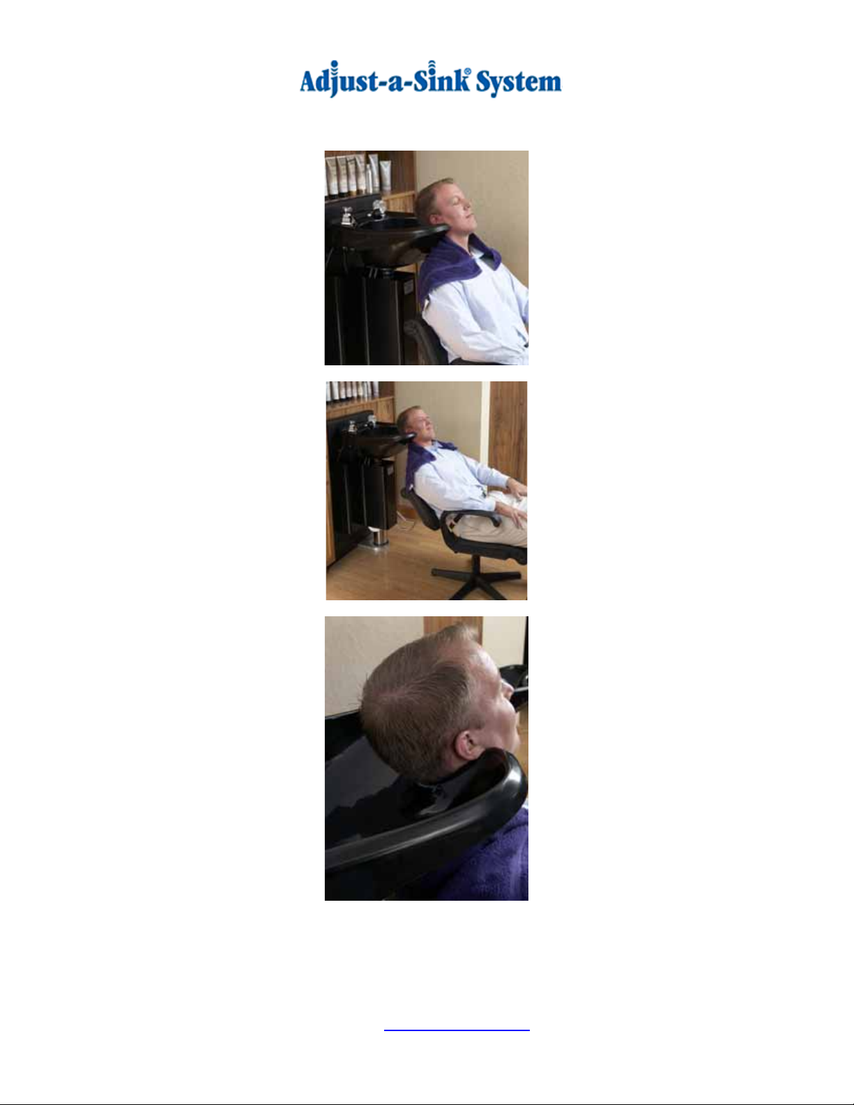
OPERATION OF THE ADJUST-A-SINK®
We suggest that stylists “be creative” in adjusting the sink to fit their clients, as each person is unique
in their body type. The Adjust-A-Sink
£
can be adjusted to improve the shampoo experience for most
everyone with a little thought and experimentation with height adjustments and head and body
positions. Note that the foot pedal swivels to allow for stylist preference. The concept behind the
adjustable height, Adjust-a-Sink
®
is to position the client in a manner that allows them to sit as upright
as possible to allow their weight to be evenly distributed throughout the body so as to alleviate
pressure on the neck and lower back.
1. Pump the Adjust-a-Sink
®
up higher than the client’s neck and shoulders.
2. Position the client in the shampoo chair so the back of the chair and the neck of the
shampoo bowl are aligned vertically. The client will usually prefer a more upright seating
position. We suggest the use of an adjustable back, fixed position shampoo chair if
possible.
3. Lower the Adjust-a-Sink
®
to the client’s comfort level - the client’s neck should fit snug and
comfortable, without pressure, against the shampoo bowl.
4. For clients in a wheelchair, use the same method noted above and ensures the bowl is up
high enough to clear the wheelchair’s handles and back.
5. Ensure the client’s head is tilted so their forehead is over the bowl. You may need to lower
the bowl slightly, and or further recline the client to obtain this desired position. In this
position, and with moderate water pressure, you should be able to provide for a
comfortable and dry shampoo. Again, the Adjust-a-Sink
®
works best with the client sitting
as upright as possible.
See photos on page 11 for proper client positioning.
Download the Stylist Tips from the Resource Page on the Website.
View the Senior Care Videos on the Website.
11 of 11
Operation of the Adjust-a-Sink® (cont.)
Position the Client Like This
Not Like This!
Note: Proper Neck/Bowl Position
C SCHEFF
5
PROHIBITED.
ROUGH-IN FOR
4
PLUMBING
DO NOT SCALE DRAWING K100-87SHEET 1 OF 1
4/17/08
E
5-3-10
UNLESS OTHERWISE SPECIFIED:
SCALE: 1:8 WEIGHT:
REV
DWG. NO.
A
SIZE
TITLE:
Accessible Systems, LLC
NAME DATE
COMMENTS:
Q.A.
MFG APPR.
ENG APPR.
CHECKED
DRAWN
THREE PLACE DECIMAL
BEND
FINISH
3
NEXT ASSY
TWO PLACE DECIMAL
MATERIAL
PROPRIETARY AND CONFIDENTIAL INTERPRET GEOMETRIC
USED ON
2
APPLICATION
K100 3-STAGE
TOLERANCING PER:
DIMENSIONS ARE IN INCHES
TOLERANCES:
FRACTIONAL 1/16
ANGULAR: MACH
THE INFORMATION CONTAINED IN THIS
DRAWING IS THE SOLE PROPERTY OF
ACCESSIBLE SYSTEMS, LLC. ANY
REPRODUCTION IN PART OR AS A WHOLE
WITHOUT THE WRITTEN PERMISSION OF
ACCESSIBLE SYSTEMS, LLC IS
1
FINISHED
FLOOR
(REF)
"
WASTE DRAIN
STUBOUT
8
(REF)
4"
WATER SUPPLY
STUBOUT
(REF)
FOR WATER SUPPLY
CLEARANCE HOLES
7/8
LINES
A
2-1/2
22
11
B
33
4-1/8
2x
2-1/4
CLEARANCE HOLE
FOR WASTE DRAIN
PIPE
NOTE: FOR USE WITH MARBLE PRODUCTS 3000W SHAMPOO BOWL WITH OR WITHOUT HAIR INTERCEPTOR
Waste Drain and Water Supply Configurations
Description Drain Type Dimension A
Min Dimension A
Max Dimension B
Min Dimension B
Max
"Rough In" New construction or
remodel Standard with or
without Hair Trap 12" 14-3/8" 10" 19"
"Retro-fit" With existing waste
drain height of 14 3/8"-19" High Drain with or
without Hair Trap 14-3/8" 19" 10" 14"
NOTE:
1)REFERENCE THE TABLE FOR THE
APPROPRIATE WATER SUPPLY AND DRAIN
DIMENSIONS.
2)THE DENOTED DIMENSIONS ARE CRITICAL
LOCATIONS FOR THE PIPES PASSING THROUGH
THE MOUNTING PANEL. ENSURE ALL PIPES
PASSING THROUGH FALL WITHIN THESE
DIMENSIONS.
3)PLEASE ADVISE WASTE WATER DRAIN WALL
LOCATION WHEN ODERING!
Table of contents
Popular Bathroom Aid manuals by other brands


Pressalit
Pressalit R7454 Mounting instruction

Pressalit Care
Pressalit Care R391370 Mounting instruction

Drive
Drive Otter Series operating instructions

Rehaforum MEDICAL
Rehaforum MEDICAL Toilet Seat Raiser RFM quick start guide

broda
broda Sentinel Shower Commode operating manual

Eagle Health Supplies
Eagle Health Supplies 77 Series instruction sheet


