Adly Motor AS-50 User manual

OWNER’S MANUAL
AS-50
AS-50LC
GTA-50
GTA-50LC
GTC-50

1
PREFACE
May we, the manufacturer, take this opportunity to thank you for choosing our
AS/GTA/GTC-50 to serve you.
This owner’s manual is preparing for you the details as to operation and
maintenance necessarily to perform in safely. Therefore, we would like to
recommend you to read this manual before you operate the Scooter.
It is our sincere wish that you enjoy operating the AS/GTA/GTC-50 and getting
fun from it. Should you have any problems, please feel free to contact our local
dealer in your area.
Note: The information and specification stated in this manual are for reference
only subject to change without notice. Thanks!

2
CONTNETS
Page
Preface ………………………………………………………………………..………. 1
Operation Warning ………………..………………………………….……….……. 3
Safety Information ………………………..…………………………….…….....…… 4
Specification ………………………………………………………………….………. 5
Periodical Check and Services ……………………………………….….…………. 10
Pre Operating Inspection …………………………………………………..………. 11
Operation …………………………………………………………………….………. 14
Maintenance ……………………………………………………………….…...…… 26
Correct Way of Driving …………………………………………………......…….. 35
Abnormalities and Trouble Shooting ……………………………………………… 39
Product Identification Number ……………………………………………………. 40
Pre-Delivery Inspection ……………………………………………….……...…….. 41
Maintenance & Service Records …………………………………………………. 42
Abnormalities Service Records……………………………………………………. 45

3
OPERATION WARNING
THIS VEHICLE IS NOT A TOY AND CAN BE HAZARDOUS TO OPERATE.
NEVER OPERATE THIS VEHICLE WITHOUT PROPER INSTRUCTION.
THIS VEHICLE IS NOT FOR YOUTH UNDER 14 YEARS OLD.
ALWAYS WEAR A HELMET!
READ THIS OWNER’S MANUAL CAREFULLY.
IT'S DANGEROUS TO DRIVE ON AN UNCLEAR ROAD CONDITION.
LOWER VEHICLE SPEED WHEN DRIVING AT NIGHT.
NEVER CONSUME ALCOHOL OR DRUGS BEFORE OR DURING RIDING.
NEVER OPERATE THIS VEHICLE ON HILLS TOO STEEP.
ALWAYS INSPECT YOUR VEHICLE EACH TIME YOU USE IT.

4
SAFETY INFORMATION
Don’t allow your child to ride.
Read all warning sticks on vehicle and follow the instruction.
Keep a safety distance between your vehicle and other vehicles.
Take a training course if you are a beginner.
This vehicle is designed to be operated only on level, on road surfaces, free
of obstacles.

5
SPECIFICATION
MODEL AS-50 AS-50LC
LENGTH 1950 mm
WIDTH 710mm
HEIGHT 1130mm
WHEEL BASE 1290mm
NET WEIGHT 87KG
ENGINE TYPE 2-STROKE, Single Cylinder
COOLED FORCE AIR COOLED LIQUID COOLED
DISPLACEMENT 49 CC
BORE STROKE 40.0 X 39.2 mm
COMPRESSION RATIO 7.0 : 1
IGNITION C.D.I
STARTER ELECTRIC/KICK
FRONT SUPENSION TELESCOPE TYPE
REAR SUPENSION HYDRAULIC SHOCK ABSORBER
TRANSMISSION C.V.T.
TIRE F:130/70-12, R:130/70-12
FRONT BRAKE DISC
REAR BRAKE (B/D) DRUM

6
SPECIFICATION
MODEL GTA-50 GTA-50LC
LENGTH 1950 mm
WIDTH 710mm
HEIGHT 1130mm
WHEEL BASE 1290mm
NET WEIGHT 87KG
ENGINE TYPE 2-STROKE, Single Cylinder
COOLED FORCE AIR COOLED LIQUID COOLED
DISPLACEMENT 49 CC
BORE STROKE 40.0 X 39.2 mm
COMPRESSION RATIO 7.0 : 1
IGNITION C.D.I
STARTER ELECTRIC/KICK
FRONT SUPENSION TELESCOPE TYPE
REAR SUPENSION HYDRAULIC SHOCK ABSORBER
TRANSMISSION C.V.T.
TIRE F:130/70-12, R:130/70-12
FRONT BRAKE DISC
REAR BRAKE (B/D) DRUM

7
SPECIFICATION
MODEL GTC-50
LENGTH 1750 mm
WIDTH 685mm
HEIGHT 1140mm
WHEEL BASE 1220mm
NET WEIGHT 81KG
ENGINE TYPE 2-STROKE, Single Cylinder
COOLED FORCE AIR COOLED
DISPLACEMENT 49 CC
BORE STROKE 40.0 X 39.2 mm
COMPRESSION RATIO 7.0 : 1
IGNITION C.D.I
STARTER ELECTRIC/KICK
FRONT SUPENSION TELESCOPE TYPE
REAR SUPENSION HYDRAULIC SHOCK ABSORBER
TRANSMISSION C.V.T.
TIRE F:130/70-12, R:130/70-12
FRONT BRAKE DISC
REAR BRAKE (B/D) DRUM

8
SPECIFICATION
AS-50 GTA-50
Front light 12V 35W/35W 12V 35W/35W
Position light 12V LED 12V LED
Rear / Brake light 12V LED 12V LED
Signal light 12V LED 12V LED
Speedometer indicator 12V 3.4W
Signal indicator 12V 1.7W
High beam indicator 12V 1.7W
Safety fuse 10A
Battery 12V 5A
Engine oil capacity 2 Stroke Only (SAE20W)
Fuel tank capacity 6.0 Lit
Gear oil capacity 0.10 Lit, SAE 90W
Disc brake fluid DOT 4 OR 3 BRAKE FLUID

9
SPECIFICATION
GTC-50
EC US
Front light 12V 35W/35W 12V 35W/35W
Position light 12V 5W
Rear / Brake light 12V 21/5W 12V 21/5W
Signal light 12V 10W 12V 21W
Speedometer indicator 12V 3.4W
Signal indicator 12V 1.7W
High beam indicator 12V 1.7W
Safety fuse 10A
Battery 12V 4A
Engine oil capacity 2 Stroke Only (SAE20W)
Fuel tank capacity 6.0 Lit
Gear oil capacity 0.10 Lit, SAE 90W
Disc brake fluid DOT 4 OR 3 BRAKE FLUID

10
PERIODICAL CHECK & SERVICES
Regular Service Mileage (KM)
ITEM 300 1000
2000
3000
4000
5000
6000
7000
8000
9000
10000
Fuel Filter R R
Brake System I I I I I I I I I I I
Drive Belt Check each 5000Km, replace if wear or cranny
Air Cleaner Change element at every 5000 Km or if necessary
Nuts, Bolts T T T
Gear Oil R R R
Carburetor I I
Spark Plug Clean at every 2000 Km or if necessary
Tire I I I I I I I I I I I
Battery I I I I I I I I I I
Pulse Air Filter I R R
Muffler Catalyst I I I
Fuel Line I I I
Coolant Check every ride, replace every 10,000 km.
Notes: 1. R: Replace, A: Adjust, C: Clean, T: Tighten, I: Inspect and clean
2. When exceeding the listed mileage, perform maintenance according to the listed
intervals.
11
PRE OPERATING INSPECTION
CHECK STEERING HANDLE
1. Check its easiness for turning to the left and right.
2. Check any tie-up by brake cables.
3. Check any abnormalities, if so, please contact your local dealer for inspection and
adjustment.
4. Check brake lever for effective braking. Braking free play should be between 1-2 cm
after brake adjustment.
CAUTIONS
Screw groove must be aligned with lock position after adjustment, any slight
deviation may result in braking play change and cause danger as brake applied.
12
PRE OPERATING INSPECTION
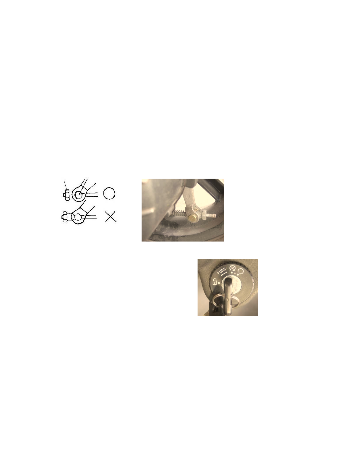
Brake performance inspection: Try braking soon as you are driving off.
CHECK BRAKE LIGHT
1. Turn main switch to “ ON ” position.
2. Apply separately of the front and rear brake lever to
see is brake light functions normally.
3. Check brake light cover for any dirt or breaking.
Adjusting Adjust screw

13
PRE OPERATING INSPECTION
CHECK TURN SIGNAL LIGHTS
1. Turn main switch to “ON” position.
2. Turn on signal light, check the function for right and left.
CHECK TIRE PRESSURE.
STANDARD TIRE PRESSURE
One passenger Two passenger
Front ………………………… 1.25 kg/
2
cm
(18 psi) 1.75 kg/
2
cm
(25 psi)
Rear ………………………… 1.75 kg/
2
cm
(25 psi) 2.25 kg/
2
cm
(32 psi)
Check tire pressure to see if they are normal.

14
PRE OPERATING INSPECTION
Check if there is any gravel in the tread grooves or any nail puncture. If so clean it.
Check for any crack or heavy worn-out, then replace it with new ones, if worn-out
exceeds the limit.
CHECK FRONT & REAR SHOCK ABSORBERS
Apply pressure on both front steering handle and seat to check the function of front
and rear absorbers.

15
OPERATION
MAIN SWITCH (GTA)
At this position, power is cut off, the engine stops.
The key can taken out
At this position, power is connect to start the engine.
The key can taken out
At this position, handlebar is lock to prevent pilferage.
The key can taken out.
CAUTIONS
Check and ensure handlebar is locked as the key is at “LOCK” position, and
take out the key to prevent pilferage.

16
OPERATION
MAIN SWITCH (GTC)
OFF
To turn off the engine.
The Key can be removed.
ON
To start the engine.
The Key can be taken out.
CAUTIONS
IF OIL INFICATOR LIGHT IS ON, IT SHOWS OIL IS INSUFFICIENT AND SHOULD BE
REFILLED AT THE DEALER’S SERVICE STATION.
IF YOU FIND THAT OIL INDICATOR LIGHT DOES NOT FUNCTION, MAYBE THE
FUSE IS BURN OUT, OR BATTERY NEED TO BE RECHARGED, OR CIRCUIT
ABNORMAL.
IF THE LIGHT GLOWS WHILE DRIVING, IT INDICATES OIL INSUFFICIENT AND
NEED TO BE ADDED.

17
OPERATION
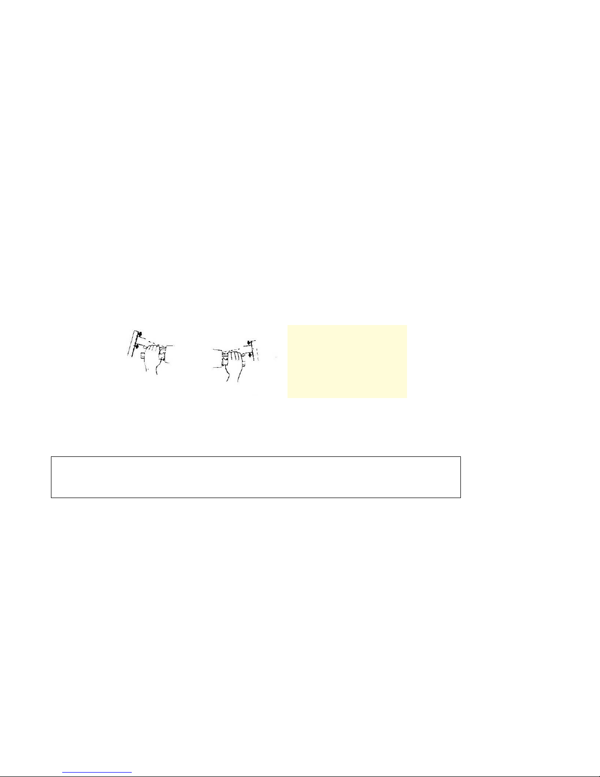
HANDLEBAR LOCK
Turn handlebar to the left, then press and turn the key form “OFF” to “LOCK”.
Thus, handlebar is lock and key can be removing.
Handlebar will be unlocked immediately while the key is turned to “OFF” position.
CAUTIONS
1. After locking, turn the handlebar gently to make sure whether is locked or not.
2. During riding, never turn the main switch to “LOCK” position

18
OPERATION
ELECTRIC STARTER
Press the butter and hold brake level to start up the
engine.
CAUTIONS
1. When press the button, be sure to pull up the front or rear brake lever in order
to connect the power supply.
2.Do not press the starter button as engine is running.
HAND LIGHT SWITCH
At this position “”,headlightposition light and
instrument light go out together.
At this position “ ”, position light and
instrument light go out together (they will not light if
The engine is not start ).
At this position “ ”, headlight will light (it will
not light if the engine is not started).

19
OPERATION
ELECTRIC STARTER
EMERGENCY STOP SWITCH (US)
ENGINE RUNNING
ENGINE STOP
North America model
only
This manual suits for next models
4
Table of contents


