Admiral ACC-0206 User manual

ACC-0206
Digital, Multi-Function,
GPS Speedometer
1:1
Contents
Notice
Product Accessories List
Product Specification
Product Wiring Diagram
User Interface
User Operation
Product Operation
Physical Features
Specification & Parameter
Product Installation
Product Dimension
1.Please make sure to refer to the installation instructions in the Operating Instructions to avoid damage caused by installation errors.
2.The product included the battery inside and cannot be replaced, do not disassemble or replace the battery by yourself.
3. Do not pull the wiring when using it to prevent falling off or poor contact happened.
4. Please install the product in a proper location to avoid the possibility of this product being hit and prevent damage to the product.
5. The product is waterproof, but cannot be used in deep water or soaked in rain for a long time.
6. Please use the product at the specified temperature, high temperature environment may cause damage to the product.
Notice
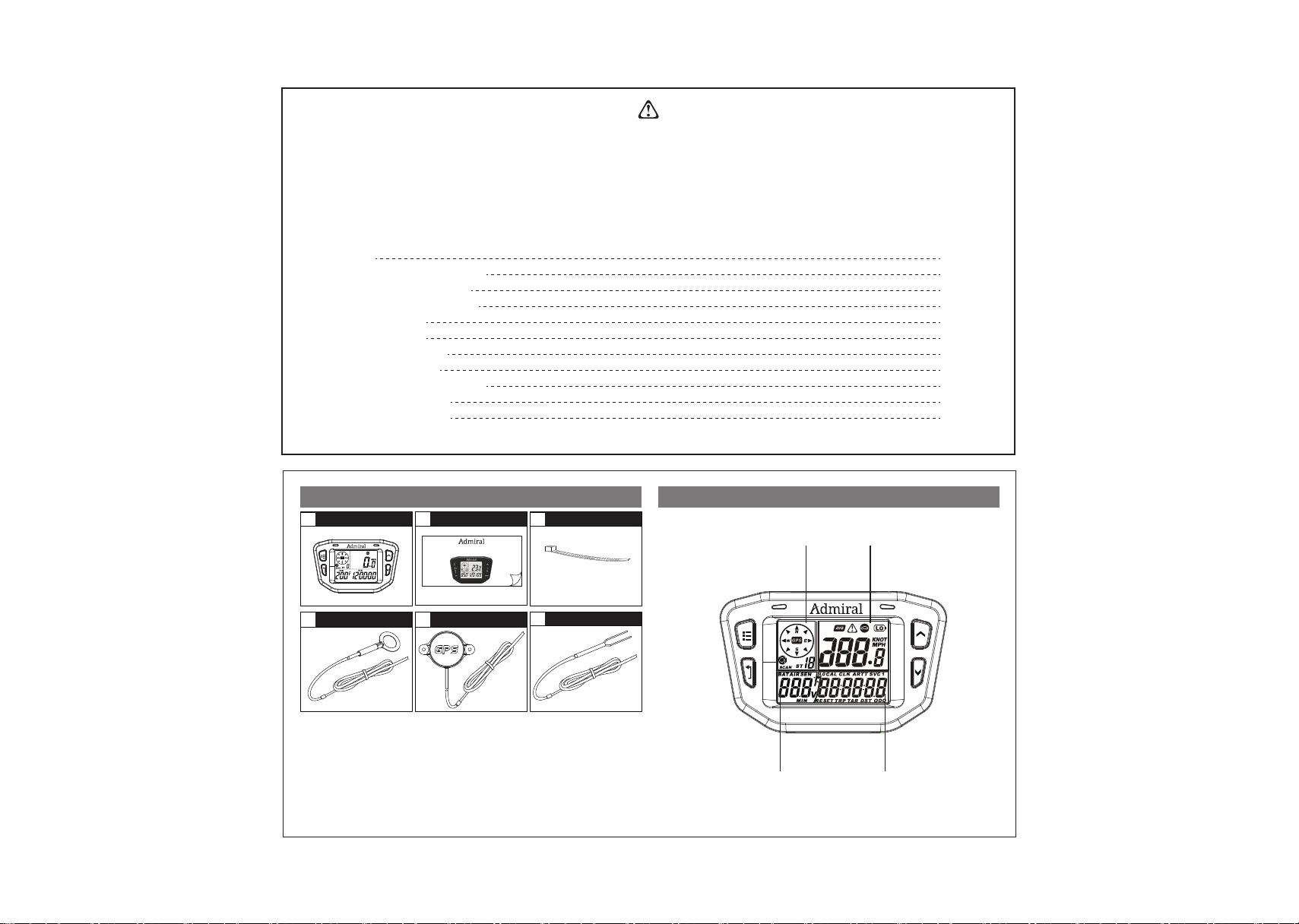
Product Accessories List
Product*1
1 2
User Manual*1
4
GPS Sensor*1
5
Power Wire*1
6
Cable tie*3
3
X3
Temp
Sensor
PT100*1
Product Specification
- 1 -
- 2 -
1:1
1
2
2
4
5
5
8
15
16
17
18
MENU
SET
UP
DOWN
MENU
SET
UP
DOWN
Speed display
Clock/MileageVoltage/Temperature
Motion direction
Number of satellite
ACC-0206
Digital, Multi-Function,
GPS Speedometer

Please install the product and wiring according operation Instruction
to ensure the normal working.
Function Icon Units Range
Odometer
Trip Mileage
Target Mileage
Total Hours
Job Hours
Clock
SVC Hours 1
SVC Hours 2
Function Icon Units Range
The Air Temperature for reference only, it maybe existed deviation with actual value.
Battery Voltage
Maximum
Battery Voltage
Engine
Temperature
V 12-36V
72V
400°
V
V
Temperature
sensor
Temperature sensor
Power Input
Power Input
Fasten the black shielded wire's ring terminal near
engine or motor for temperature reading. Do not
connect to DC motor power terminals.
- 3 -
1:1
- 4 -
Product Wiring Diagram
KM/H or M/H or KNOT
KM/H or M/H or KNOT
KM/H or M/H or KNOT
H:M
H:M
H
H
H:M:S
0-1000KM/H
0-99999.9H
0-99999.9H
0-500000KM
0-500000KM
0-1000H
0-1000H
24H
Air Temperature
Engine
Temperature
Alert
Temperature
Maximum
Engine Temperature
-20℃—+70℃
-4℉—+158℉
-20℃—+250℃
-4℉—+482℉
-20℃—+250℃
-4℉—+482℉
-20℃—+250℃
-4℉—+482℉
℃/℉
℃/℉
℃/℉
℃/℉
MENU
SET
UP
DOWN
GPS Sensor
1. 2.
Two installation ways
1. screws(installation surface may be broken,
please reconsider it before installation)
2. 3M double-sided adhesive tape
(Before installation, please clean the installation
surface and keep it without dust,water and greasy dirt
Current Speed
KM/H or M/H or KNOT
KM/H or M/H or KNOT
KM/H or M/H or KNOT
KM/H or M/H or KNOT
0-399KM/H
Average Speed
Maximum Speed
Alert Speed
/
/
/

User Interface User Operation
All the information that pilot is on one of these 3 screens. The user
has the choice of staying on Screen 1 ,Screen 2 or Screen 3.
Press "MENU", the 3 main interfaces could be switched freely.
1 Screen 1 Operation
Screen 1:
●Direction of motion
●Number of satellites
●Speed
●AIR Temperature
●Clock
2 Screen 2 Operation
Screen 2:
●Direction of motion
●Number of satellites
●Speed
●Battery voltage
●Odometer (ODO)
Under the Screen 1 interface, press the “UP” or “DOWN” button can
view more data information.
Under the Screen 2 interface, press the “UP” or “DOWN” button can
view more data information)
●Max speed
●Max AIR temperature
●Clock
●Average speed
●Max battery voltage
●Clock
●Alert speed
●Min battery voltage
●Clock
●Max speed
●Max engine temperature
●Trip distance
●Average speed
●Max battery voltage
●Target distance
Screen 1
●Direction of motion
●Number of satellites
●Speed
●AIR Temperature
●Clock
Screen 2
●Direction of motion
●Number of satellites
●Speed
●Battery voltage
●Odometer (ODO)
Screen 3
●Direction of motion
●Number of satellites
●Speed
●Engine TEMP
●Total time (ART)
Back to Main Interface
At Circle
1:1
- 5 -
- 6 -
UP
UP
UP
UP
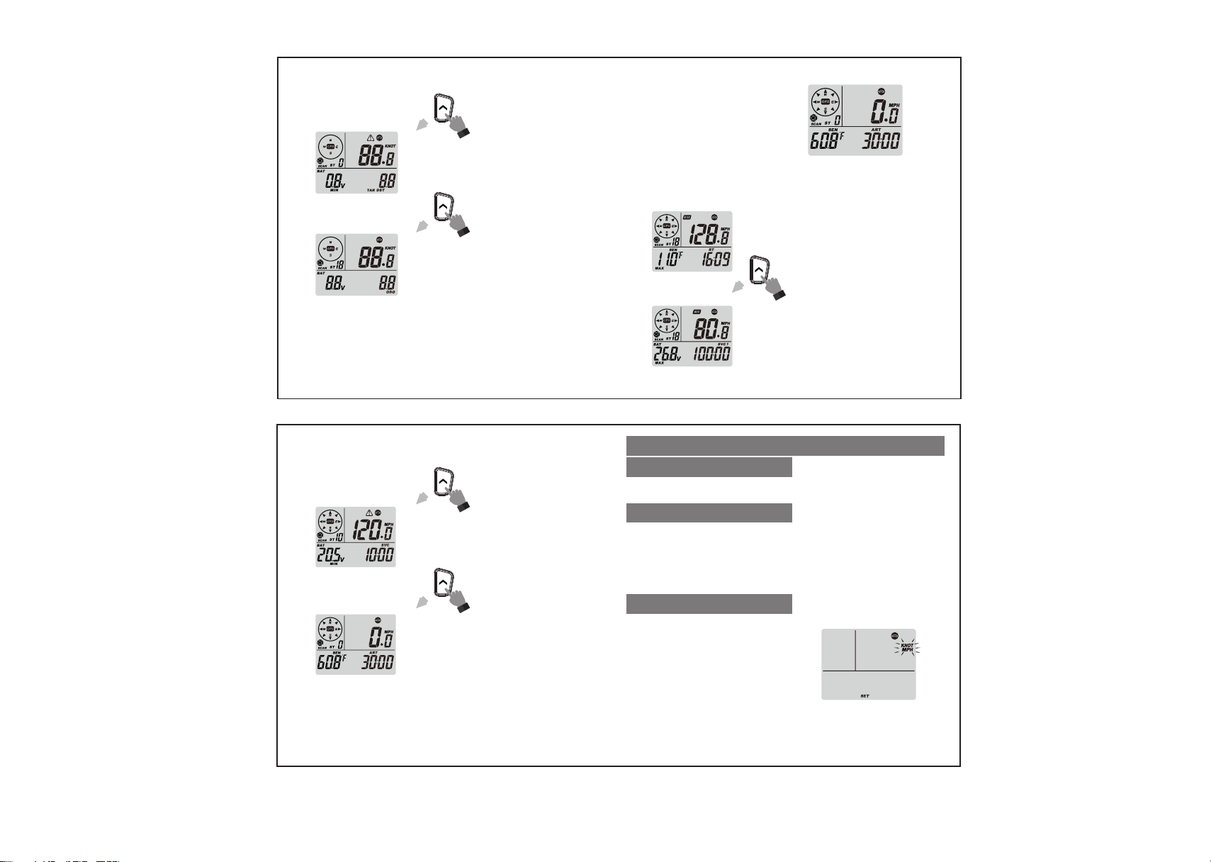
Product Operation
1.Setup speed units (Defaults:KM/H)
3 Screen 3 Operation
Screen 3:
●Direction of motion
●Number of satellites
●Speed
●Engine TEMP
●Total time (ART)
Under the Screen 3 interface, press the “UP” or “DOWN” button can
view more data information)
●Max speed
●Max engine temperature
●Job hours
●Average speed
●Max battery voltage
●SVC1 hour
●Alert speed
●Min battery voltage
●SVC2 hour
●Alert speed
●Min battery voltage
●Target distance
Back to Main Interface
At Circle
Back to Main Interface
At Circle
a) Press any button to turn on the device.
b) Press and hold the “MENU” button for 2s to off at any interface.
A.Product Startup and shutdown
a) Press the “MENU” button until display Screen 1 or Screen 2 or Screen 3.
a) Press “SET” + “DOWN” 1s to exit.
b) Exit automatically 30s later.
c) Press “SET” or “MENU” to switch the Setup.
b) Press the “UP” or “DOWN” button until you get desired unit , release the
button and finish your confirm.( Press the “SET” button can enter next setup)
b) Setup at circle as following
KM/H → Speed Alert → Temp Unit → Temp Alert → SVC1→ SVC2→ TAR DST
→ CLK→ H
B.Setup Mode
C.Exit Setup
a) Press and hold the “SET” button
until screen display “SET” icon and
“KM/H” icon start flashing.
1:1
- 7 -
- 8 -
UP
LOCAL CLK→ H →M→S
UP
UP
UP
UP

2. Setup alert speed value (Defaults: 100KM/H)
3. Setup Temperature units (Defaults: C )
4. Setup Alert Temperature Value (Defaults: 100℃)
Press the “UP” or “DOWN” button until you get desired alert speed value ,
release the button and finish your confirm.( Press the “SET” button can enter
next setup) .
Press the “UP” or “DOWN” button until you get desired alert temperature value ,
release the button and finish your confirm.( Press the “SET” button can enter
next setup)
6. Setup SVC (Defaults: 0—1000H)
7. Setup Target mileage (Defaults: 0—1000KM)
Press the “UP” or “DOWN” button until you get desired SVC Timer value ,
release the button and finish your confirm.( Press the “SET” button can enter
next setup)
8. Setup clock mode (CLK )
Press the “UP” or “DOWN” button until you get desired clock mode , release
the button and finish your confirm.( Press the “SET” button can enter next setup)
Press the “UP” or “DOWN” button until you get desired Target mileage value ,
release the button and finish your confirm.( Press the “SET” button can enter
next setup)
Press the “UP” or “DOWN” button until you get desired temperature unit ,
release the button and finish your confirm.( Press the “SET” button can enter
next setup)
1:1
- 9 -
- 10 -
5. Setup SVC1 (Defaults: 1000H )
Press the “UP” or “DOWN” button until you get desired SVC1 Timer value ,
release the button and finish your confirm.( Press the “SET” button can enter
next setup)
H:0-23hour
M:0-59minutes
S:0-59seconds
Select CLK mode Select LOCAL CLK mode
UP
DOWN
or
UP
DOWN
or
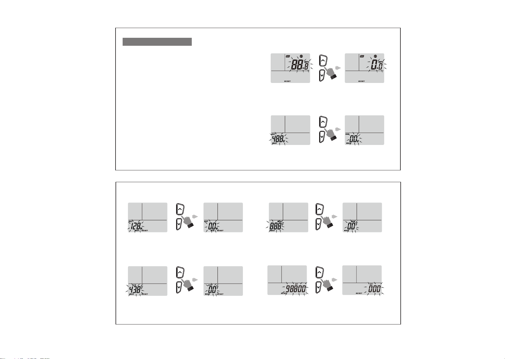
C.Reset
a) Press and hold the “SET”button for 2s to into reset at any sub-interface.
a) Press button “UP/DOWN”, reset the value of the current interface.
b) Product defaulted get into the Max Speed Reset Interface, the current reset
value start flashing.
b) Press button “MENU/SET” to switch to the next desired value.
1.Get into reset
2.Reset Operation
a) Press and hold buttons “SET”+ “DOWN” for 1s to exit the reset interface.
b) It will exit without no operation within 30s.
3.Reset exit
a) Reset the Max Speed Value
d) Reset the Max Temp of air Value
c) Reset the Min Voltage value
4.Reset Interface demo
Press UP/DOWN to reset
Before After
Press UP/DOWN to reset
After
Press UP/DOWN to reset
Before After
1:1
- 11 -
- 12 -
Before
e) Reset the Max Temp of Sensor Value
Press UP/DOWN to reset
Before After
f) Reset Job Hours Value
Press UP/DOWN to reset
Before After
b) Reset the Max Voltage Value
Press UP/DOWN to reset
Before After
UP
DOWN
or
UP
DOWN
or
UP
DOWN
or
UP
DOWN
or
UP
DOWN
or
UP
DOWN
or

g) Rest Trip Distance Value
Press UP/DOWN to reset
Before After
1:1
- 13 -
- 14 -
D. Other
a) The upper left of LCD display number of satellites and
direction of motion.
b) The upper right of LCD display current speed.
c) The lower left of LCD alternate display battery voltage and
ambient temperature.
d) The lower right of LCD display time and mileage.
Theme 1 : speed+ AIR temperature+clock
1.SM002 will enter into screen 1 after reset
The main display when standby
2.The backlight will off without any operation within 30s. It will
only display clock and no other display if without any operation
for 5 min(as below picture); it will back to normal display when
have button operation and GPS speed.
Setting time: Please set it after receiving the stallite signal
and the stallite keep good.
If user choose "CLK" mode, only enter the hours value to
finish the setting, no need to enter the minutes and
seconds.
If user choose "LOCAL CLK", enter all the values including
hours, minutes and seconds to finish the setting.
UP
DOWN
or

B.Warning alert
Specification & Parameter
Physical features
No
warning type
Settable range
LCD Reminder
Method
LED Reminder
Method
1
2
3
4
Speeding alert
Over-temperature alert
Low voltage of
internal battery
Bad satellite signal
0-399KM/H
-20℃-250℃
Warning icon flashes
Battery icon flashes
“SCAN”icon flashes
Red light flashes
Red light flashes
Red light flashes
Product Name
1.Specifications 2.Parameter
12-72VDCExternal Voltage
Supply
RL-SM002
Black
ABS
White backlight
365g
IP67
Item No. 3.7v lithium battery
500mAh rechargeable
Internal Battery
Color
Housing Material
Product Size
Display Mode
Display window size
Product Weight
Waterproof rate
0-399KM/H
Speed Range
-20-250℃
Temperature Range
0-99999.9H
Total Time
0-99999.9H
0-500000KM
0-500000KM
(Can be reset)
(Can be reset)
Partial time
Total Mileage
Partial Mileage
1:1
- 15 -
- 16 -
1.When reach to the alert value, red flashing at twice every 5s, and LCD
display the current reminder content.
2. When happen Multiple reminders at the same time, display alternately.
3. Press and hold the button “SET” for 1s to clear the reminder.
A.SVC alert
Physical features
No
SVC type
Settable range
LCD Reminder
Method
LED Reminder
Method
1
2
3
SVC1
SVC
Target mileage
reached alert
0-1000H
0-1000H
0-1000H
“SVC1”icon flashes
“SVC2”icon flashes
“TAR”icon flashes
Yellow Flashes
Yellow Flashes
Yellow Flashes
1.Multiple reminders may occur simultaneously.
2. Press and hold the set button for 2S to clear reminders.
57.8x43.4mm
115.6x72x23.6mm
GPS Speed table
/
/
/ /
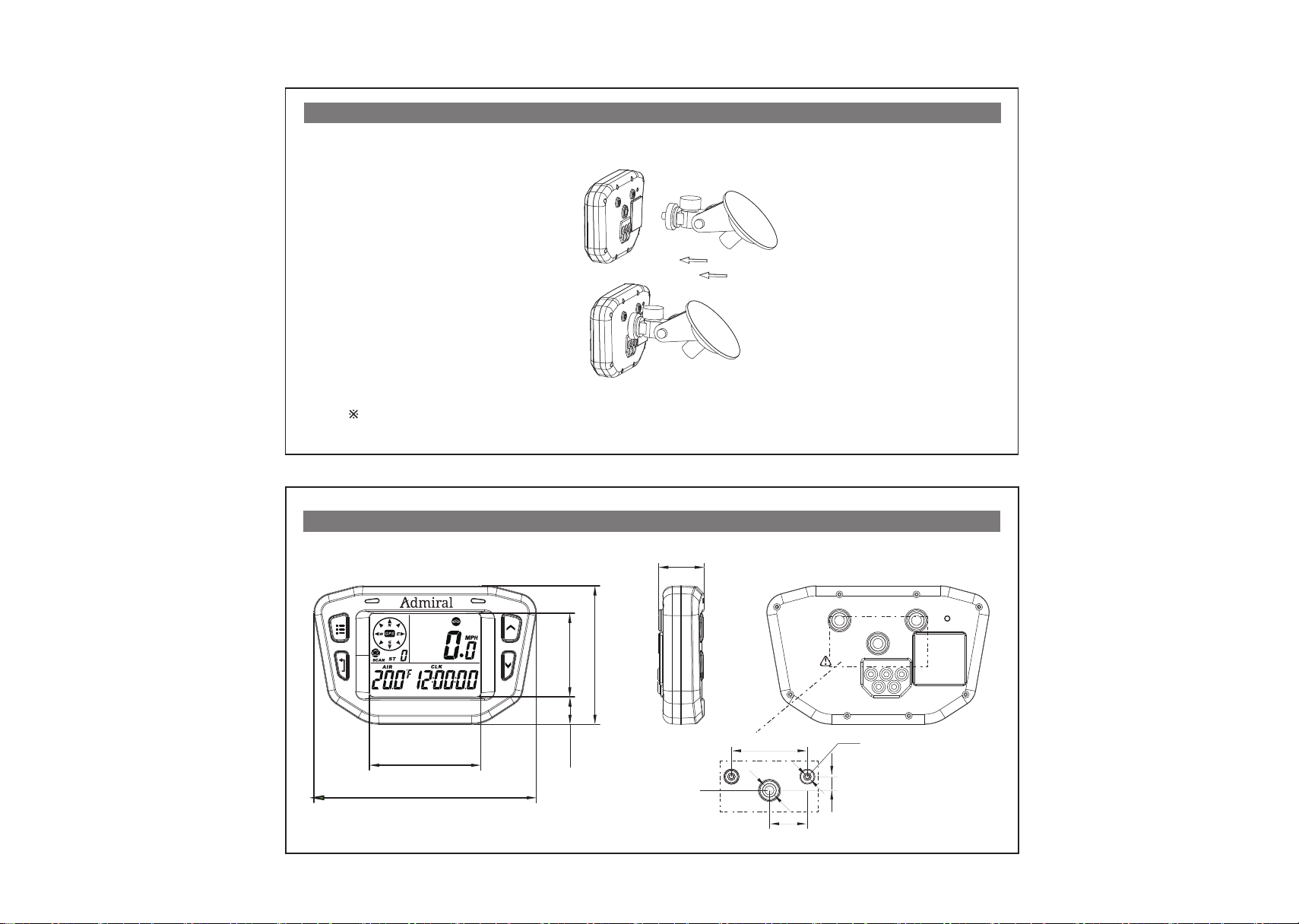
Product Dimension
Unit:mm
1:1
- 17 -
- 18 -
40
8
20
M3 Brass nut
1/4 Brass nut
14.3
57.8
43.4
72
23.6
115.6
MENU
SET
UP
DOWN
Inside contain the battery,
Keep installation location
away from the heat source.
3 - TEMP SENSOR
CONNECTION HOLE
2 - GPS SENSOR
1 - DC.POWER
4 - X
5 - X
Reset
1
4 5
2 3
Steering Column and dash mounting brackets sold separately. Visit golfcart.com for speedometer mounting options.
Installation Method 1
Product Installation
Table of contents
Popular Measuring Instrument manuals by other brands

GMI
GMI Gasurveyor 500 Series Training

PCB Piezotronics
PCB Piezotronics IMI SENSORS M606B01 Installation and operating manual

Lutron Electronics
Lutron Electronics EM-1910 Operation manual

VeEX
VeEX FX80 PON user manual

Dillon
Dillon EDXtreme EDX-1T User instructions

Rice Lake
Rice Lake Healthweigh Adjusting instructions


