Adomeit Group Veleon User manual

User Manual
Kaleidoscopic as life


Table of Content
1
1 Introduction..................................................................................................................................... 1
1.1 Veleon and its components ..................................................................................................... 2
2 Getting started ................................................................................................................................ 3
3 Advice for the driver........................................................................................................................ 6
3.1 Designated usage..................................................................................................................... 6
3.2 Checking screws and steering mechanism .............................................................................. 6
3.3 Regulatory requirements......................................................................................................... 6
3.4 Using a children’s bicycle seat ................................................................................................. 6
3.5 Intense usage........................................................................................................................... 7
3.6 Driving safety ........................................................................................................................... 7
4 Establishing readiness to travel....................................................................................................... 8
4.1 Checking the connection between frame and front end......................................................... 8
4.2 Checking and adjusting the saddle ........................................................................................ 10
4.2.1 Checking the saddle height ........................................................................................... 10
4.2.2 Adjusting the saddle height, saddle tilt and saddle position ........................................ 10
4.3 Checking and adjusting the handlebar .................................................................................. 11
4.3.1 Checking the handlebar height ..................................................................................... 11
4.3.2 Adjusting the handlebar tilt........................................................................................... 11
4.3.3 Adjusting the handlebar position.................................................................................. 11
4.4 Checking the brakes............................................................................................................... 12
4.4.1 Assignment of the brakes.............................................................................................. 12
4.4.2 Lock function of the front brake.................................................................................... 12
4.5 Use the lockout (suspension)................................................................................................. 13
4.6 Checking the tilt lock.............................................................................................................. 14
4.7 Checking the toe angle........................................................................................................... 15
4.8 Checking the steering system ................................................................................................ 15
5 Useful Tips ..................................................................................................................................... 17
5.1 Minimum height of the saddle .............................................................................................. 17
5.2 Allowed maximum weight ..................................................................................................... 17
5.3 Greasing the bike ................................................................................................................... 17
6 Adjusting Veleon ........................................................................................................................... 18

6.1 Fastening torque for bolted connections .............................................................................. 18
6.2 Separating the frame and the front end................................................................................ 19
6.3 Quick release skewers............................................................................................................ 20
6.4 Adjusting the gear shift.......................................................................................................... 21
6.5 Adjusting the brakes .............................................................................................................. 21
6.6 Adjusting the cable steering (if available).............................................................................. 22
6.7 Adjusting the damper ............................................................................................................ 23
6.8 Adjusting the tilt lock............................................................................................................. 23
7 Maintenance.................................................................................................................................. 24
7.1 General maintenance............................................................................................................. 24
7.2 Retorque the bottom bracket screws.................................................................................... 24
8 Accessory and replacement parts ................................................................................................. 25
8.1 Importance of original parts .................................................................................................. 25
8.2 Suitable replacement parts.................................................................................................... 25
8.3 Accessory ............................................................................................................................... 25
8.3.1 The cargo box ................................................................................................................ 25
8.3.1.1 Function and maintenance of the cargo box.......................................................... 25
8.3.1.2 Attaching the cargo box ......................................................................................... 26
8.3.1.3 The support wheel.................................................................................................. 27
8.3.1.4 Isofix anchorage system ......................................................................................... 29
8.3.2 Children’s seat bench .................................................................................................... 30
8.3.2.1 Attaching the seat bench........................................................................................ 30
8.3.2.2 Adjusting the belt system....................................................................................... 32
8.3.2.3 Cchildren seat bench and rain cover...................................................................... 32
8.3.3 Shield ............................................................................................................................. 33
8.3.3.1 Opening and closing the shield............................................................................... 33
8.3.4 Rain cover...................................................................................................................... 35
8.3.5 Lighting .......................................................................................................................... 37
9 EC-Declaration of Conformity original........................................................................................... 38
10 User manual of Heinzmann DirectPower System ......................................................................... 39

1
1Introduction
Welcome to the fascinating world of Veleon and thank you very much, that you have chosen this
unique way of transportation.
Veleon has highest standards regarding design, construction and production, to guarantee you the
highest possible driving pleasure. To achieve the best experience with Veleon, it is recommended that
you read the manual thoroughly before the first ride. Only the necessary understanding of Veleon and
its characteristics allow you to always be safe on your way with this vehicle.
Please always consider the road traffic regulations and ride with foresight and consideration, as not to
endanger yourself or others.
The Adomeit Group GmbH wishes you a great time with your Veleon and a safe journey at all times.

Introduction
2
1.1 Veleon and its components
01
stem
02
Lockout (suspension)
03
bell
04
handlebar
05
quick release skewers
06
Front brake
07
tires
08
wheel
09
chain guard
10
inner bearing
11
crankset
12
pedals
13
chain
14
rear derailleur
15
mudguard
16
saddle
17
rear brake

Getting started
3
2Getting started
Before your first ride, Veleon has to be taken out of the package, checked for completeness and
assembled correctly. The following parts have to be enclosed.
Package front end:
•front end
•two front-tires and nuts
•saddle and seat post
•mudguard
1
Package frame:
•frame and components
•rear carrier1
Package cargo box1:
•cargo box and components1
1
optional
Should the Veleon be delivered assembled, the following assembly steps will be omitted. You
should only pay attention to possible transport damage and check the tire pressure.

Getting started
4
Veleon is assembled as described below.
Front end:
1. Unscrew the brake caliper incl. adapter from steering knuckle.
2. Mount the mudguards1 .
•The mudguard bracket is to be attached to the steering knuckle with two screws. The
additional arm (riveted to mudguard) is fixed with the rear bolt of the brake caliper
adapter.
3. All screws for mudguard bracket and brake must be glued in with screw lock.
Use Loctite to prevent the screws from loosening.
4. Mount the front wheels, using the enclosed nuts.
5. Mount the front wheel brakes.
6. Check the air-pressure to the tires. (ca. 4,0 bar)
Frame:
1. Screw the pedals to the crank arms and tighten.
Left side- left -hand thread / right side –right-hand thread.
2. Unpack the rear derailleur and screw on the dropout
(attachment point on the frame for the wheel’s axle, (image 2-2).
•Be careful not to damage thread.
3. Insert the saddle into the seat tube and fasten it with the quick-release lever.
4. Put the carrier into the desired height and fasten the screws1.
5. Check the air-pressure of the tires (between 3 and 4 bar).
1 optional
image 2-1: Additional arm fixed on brake caliper adapter

Getting started
5
6. Install the enclosed “Clix” quick release skewers into the clamping jaws.
•The quick release lever should be attached to the jaw without slot (image 2-3). The
safety nut should prevent twisting of the locknut.
Connect the frame with the front end. (For details, see chapter 4.1 "Connecting the frame and front
end").
How to mount the cargo-box1is described in chapter 8.3.1.2.
1
Optional
image 2-2: Rear derailleur on the dropout
image 2-3 : Correct fixed quick release

Advice for the driver
6
3Advice for the driver
3.1 Designated usage
Veleon is a tilting trike for the urban environment. It is designed to ride on paved roads and dirt roads.
We explicitly advice you that Veleon is not designed to ride over trackless terrain. Such improper use
can lead to serious damage of the vehicle.
3.2 Checking screws and steering mechanism
After around 50km or the first couple of days, all screws and especially the tension of the cable steering
system has to be checked and, if necessary, adjusted.
3.3 Regulatory requirements
The driver is advised that Veleon may only be used on public streets, if it complies with the national
regulatory requirements. The driver has to inform him/herself about the requirements before driving
Veleon on public streets.
3.4 Using a children’s bicycle seat
For your own safety, and the safety of the child you are transporting, it is specifically stated, that all
spring rings have to be covered, when a children’s bicycle seat is used that is located behind the saddle.
This is the only way to prevent the child from pinching its fingers.

Advice for the driver
7
3.5 Intense usage
Like all mechanical components, Veleon is exposed to heavy stress and thus is subject to wear and
tear. Different materials and components can react differently to the exposure regarding wear and
tiredness. If the life span of a component is exceeded, the part can fail suddenly and lead to serious
injuries. All kinds of cracks, scratches or changes of color in highly stressed areas are an indicator that
the life span has been reached and that the part has to be replaced.
3.6 Driving safety
The driver is asked to follow these recommendations regarding the driving safety:
•Wearing a helmet can significantly reduce the risk head injuries in case of an accident.
•The following parts should be checked regularly:
oThe brakes
oThe tires and air pressure
oThe rims
oThe condition and tension of the steering cables
oThe connection between frame and front end
oThe condition of the chain and chain rings
•The braking distance increases on wet or otherwise slippery surfaces.
•Before beginning a ride, the roadworthiness has to be ensured.
Establishing readiness to travel
8
4Establishing readiness to travel
4.1 Checking the connection between frame and front end
Frame and front end are connected with quick release skewers. Their position has to be checked prior
to every ride.
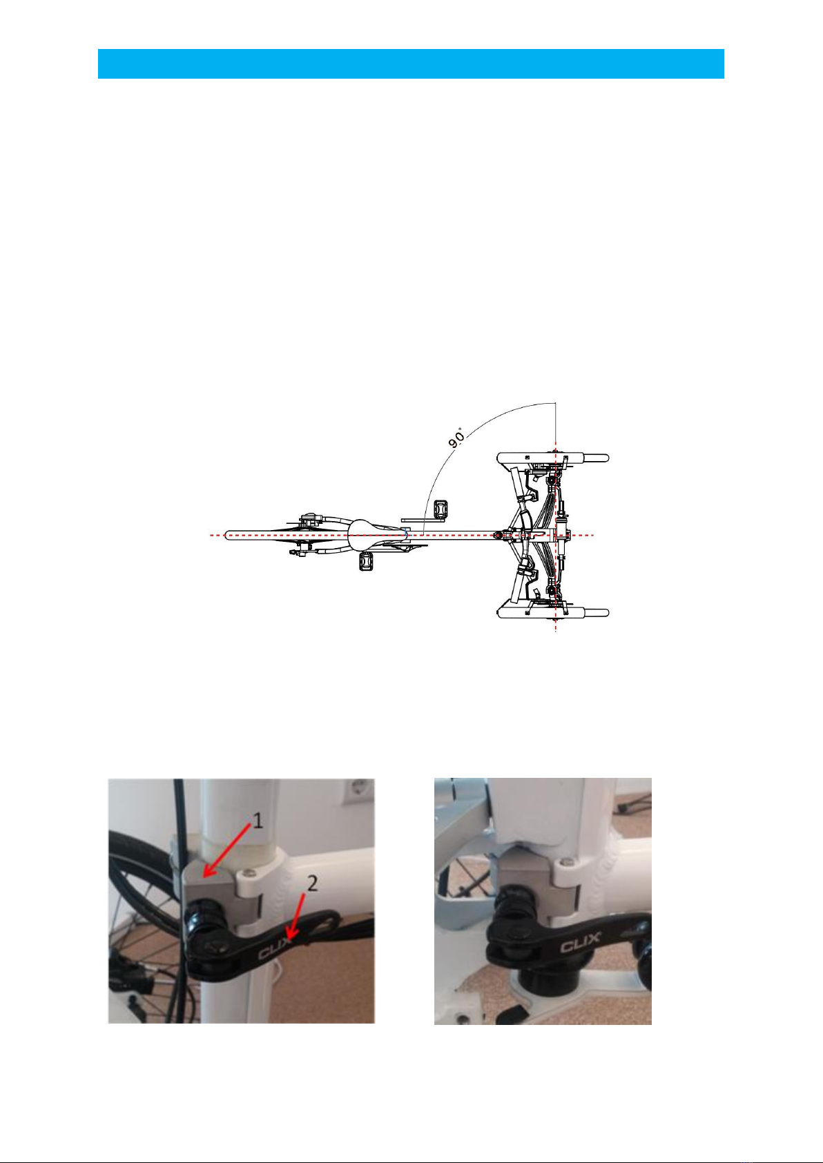
The rear part must be positioned so that it forms a right angle to the front axle.
The height of the frame has to be adjusted so that the lower jaws occupy the free space provided in
the front (image 4-2 and 4-3).
image 4-1: Positioning of frame and front end
After the front end is positioned correctly, the clamping jaws (1) are closed with the quick release
skewers (2). Adjust the quick release so that they can be closed and opened just by hand. It should be
noted, that the quick release skewers are in a horizontal position.
image 4-2: Position of the clamping jaw and quick release
image 4-3: Correct position of the lower jaws
Establishing readiness to travel
9
ADVICE
The correct positioning of the front end is crucial for the drivability of Veleon. You should therefore
check the correct positioning prior to every ride.
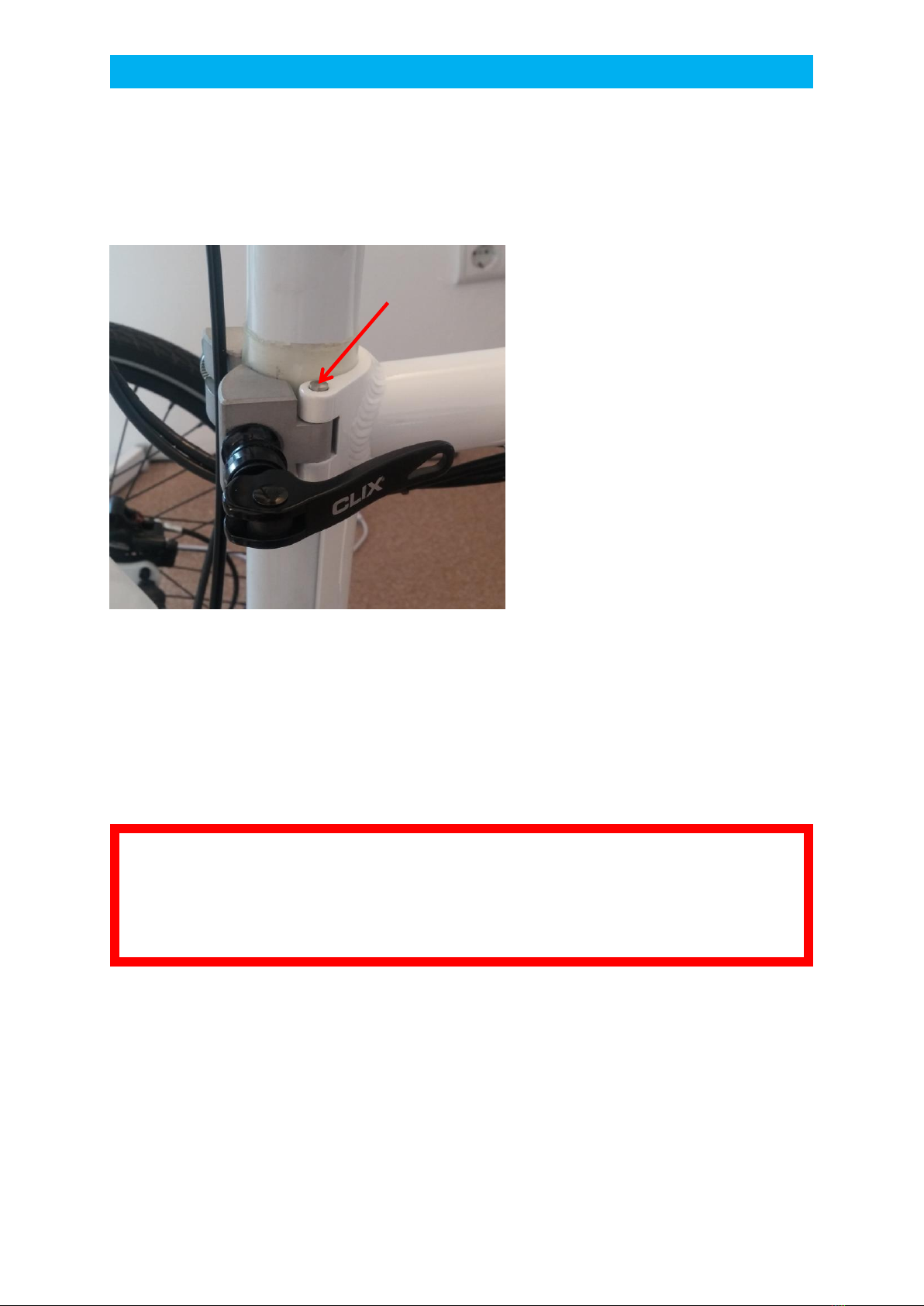
image 4-4: Position of the connecting bolt
The connecting bolts (1) should be checked for correct positioning prior to every ride. Incorrectly
positioned and/or loose bolts can be dangerous. For your own safety and of those around you, please
don’t ride Veleon in this case. Take it to a technical expert to have it checked.
•Adjust the quick release so that they can be closed and opened just by
hand.
•The frame has to be attached at the right height!
•The front axle and the frame have to be aligned in a right angle!
1

Establishing readiness to travel
10
4.2 Checking and adjusting the saddle
4.2.1 Checking the saddle height
One pedal has to be at the lowest point. Sit down on the saddle and place your heel on the pedal. If
you sit upright on the saddle and your knee is straight, the saddle has the right height.
4.2.2 Adjusting the saddle height, saddle tilt and saddle position
This formula shows, at what height the saddle should be pre-positioned: 0,885 x inseam
Adjusting the saddle tilt:
Align your bicycle saddle as horizontally as possible. Find your most comfortable seating position on a
longer bike ride. You can try to ride the bike with a saddle position tilted slightly forward. If you are
tilted slightly backward, you can quickly experience pain or physical injury.
Adjusting the saddle height:
To adjust the saddle height, loosen the quick release skewers. Adjust the seat height by pulling out the
seat post. Close the quick release. Check the saddle height. If it’s necessary, repeat this process.
Never pull the seat post out of the seat tube above the maximum mark.
It can cause injury to the rider and damage to the bike.
Adjusting the saddle position:
To adjust the saddle position, the pedals have to be in a horizontal position. Place your foot on the
front pedal and move the saddle, until the front of the kneecap and the axis of the pedal form one
vertical line. Since saddle height and saddle position influence each other, the saddle height has to be
checked and adjusted again, if the saddle is moved more than 10mm.
Establishing readiness to travel
11
4.3 Checking and adjusting the handlebar
4.3.1 Checking the handlebar height
The lower you set the handlebar, the farther you have to tilt your upper body forward. This increases
the strain on your wrists, arms, and upper body, and you need to bend your back more. The higher you
set the handlebar, the more upright you sit. Thus increases the strain on your spine through impact.
The correct handlebar height is the one where your back is in a comfortable position.
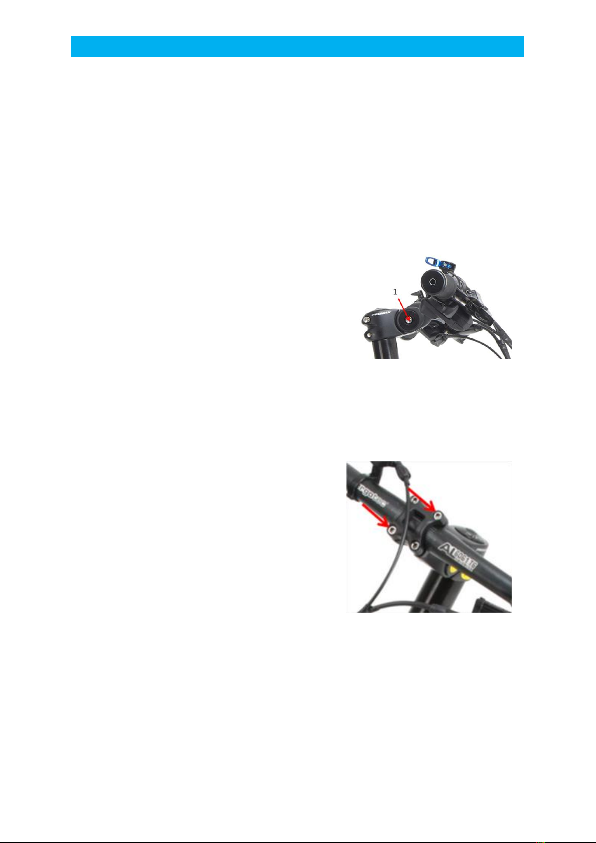
4.3.2 Adjusting the handlebar tilt
The handlebar height and the position can only be
adjusted if the screw (1) is loosened. After the screw is
loose, the handlebar can be positioned like you want.
Tighten the screw to prevent the handlebar from moving
while driving.
4.3.3 Adjusting the handlebar position
Open the Allen screws on the front of the stem and turn
the handlebar to a comfortable position. Make sure that
the handlebar is in the middle of the stem. Tighten the
Allen screws clockwise. After that you have to make sure
that the brake handles are adjusted. Loosen the Allen
screws in the grip bandage. Sit on the saddle and put your
fingers on the lever. Turn the lever until your hand forms
a straight line with your forearm. Tighten the screws
again.
image 4-6: Adjusting the handlebar position
image 4-5: Adjusting the handlebar height

Establishing readiness to travel
12
4.4 Checking the brakes
4.4.1 Assignment of the brakes
The right brake lever controls the rear wheel brake.
The left brake lever controls the front wheel brakes
4.4.2 Lock function of the front brake
image 4-7: Brake lever in loose position
image 4-8: Brake lever in closed position
If you want to use the lock function of the front brake, pull the brake lever and move the small crank
(1) to the left. If you let go of the brake lever, the crank will keep the brake lever in position and thus
blocks the front tires (image 4-7). To loosen the brake, pull the leaver and move the small crank to the
right. The brake is now loose (image 4-8).
The mechanical braking system does not have a lock function.
1

Establishing readiness to travel
13
4.5 Use the lockout (suspension)
The lever shown in image 4-9 triggers the lockout for the suspension. If the larger lever (1) is pushed
forward, the damper is set much harder. In this way the damper compresses a lot less at the same
pressure. The lockout can be released by pressing the small lever forward (2).
The lockout should be used when the cargo box is being loaded. The lockout then prevents the damper
from compressing resulting in a deflection of the front axle while driving.
The damper lockout has nothing to do with the ability of tilting. This will only be adjusted via the handle
on the handlebar described in the next chapter.
image 4-9: The lockout for the suspension
Establishing readiness to travel
14
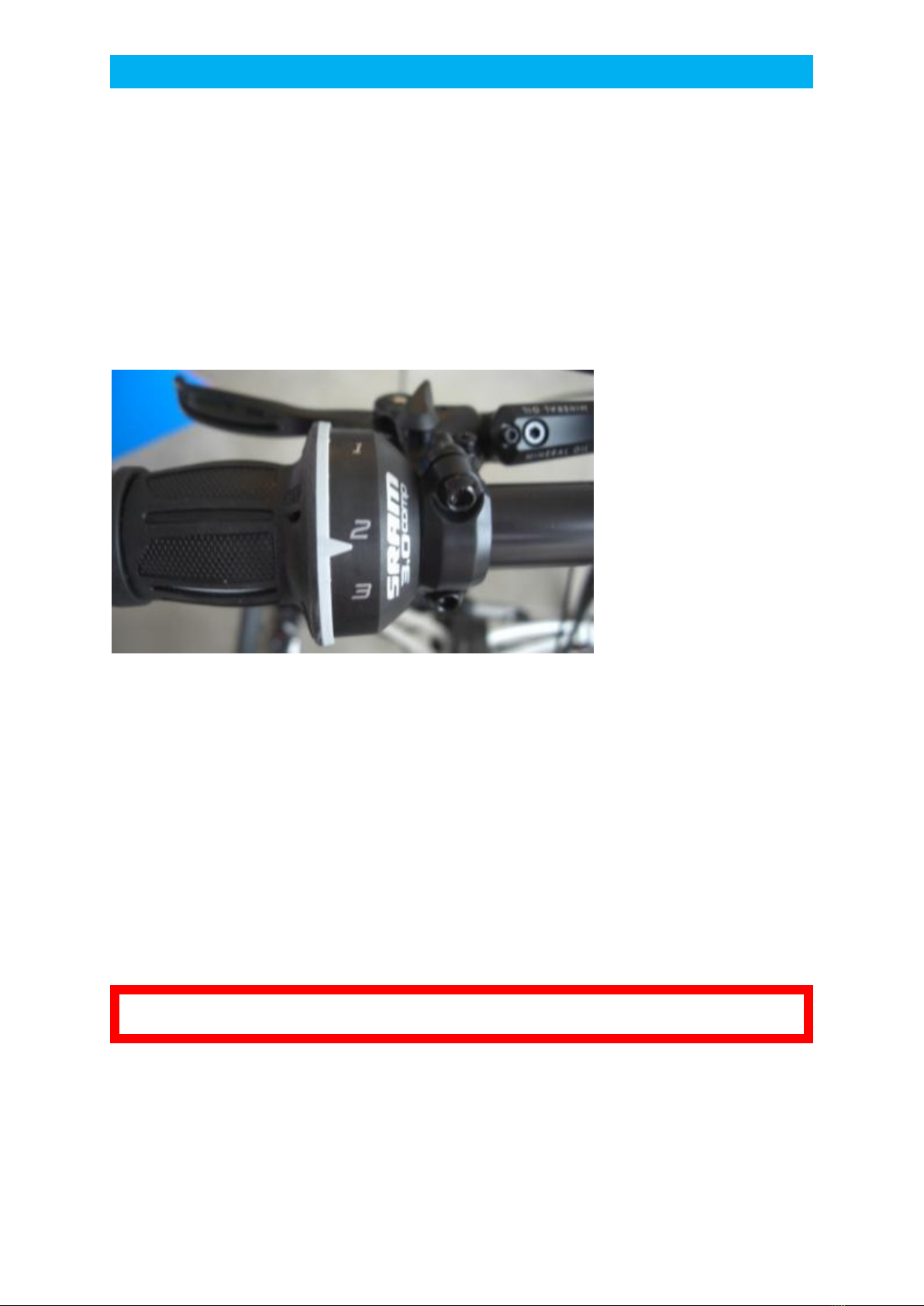
4.6 Checking the tilt lock
Veleon is equipped with a tilt lock that has 3 states.
•Free tilting (position 1, 30 tilting)
•Supported driving (position 2, 10 tilting)
•Safe stand (position 3, 0 tilting)
image 4-10: Grip shift lever for the tilt lock
In position 2, the tilting of the Veleon is limited to 10 °. This setting can be used for acclimatization and
for slow rides. We recommend position 1 with 30 ° tilting for complete maneuverability and cycling
dynamics.
Position 3 keeps Veleon in an upright position while stopping, parking, loading and unloading.
This setting is not suitable for driving!
Taking the curve safely isn’t guaranteed in Position 3.
It is recommended to check the functionality of the tilt lock before cycling Veleon.
Position 3 of the tilt lock is only for parking, not for cycling!
Establishing readiness to travel
15
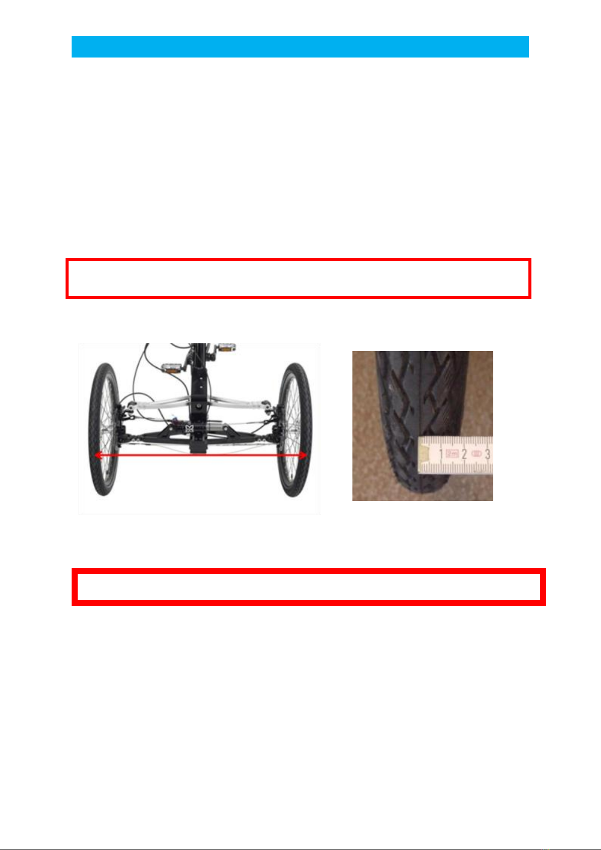
4.7 Checking the toe angle
It is very important for the driving behavior, to adjust toe angle correctly. The toe angle should be set
to 0°, meaning that both wheels are parallel when they point straight forward. If the distance at the
front and back is the same, the track is set correctly. (image 4-11) The track is adjusted via the screws
on the front and rear steering cable. In the rod steering alternatively via the turning of the tie rods.
(described in the next chapter 6.6)
image 4-11: Adjusting the toe angle
The toe angle has to be set so that the front wheels are parallel to each other!
4.8 Checking the steering system
If Veleon has a rod steering, it doesn’t usually require a correction and this chapter can be skipped.
Apart from checking the toe angle as described prior, it is very important to regularly check the tension
of the steering cable. The correct tension is crucial for the durability of the steering system. The tension
of the steering cable should be adjusted in a way that the steering is free of clearance, but still makes
image 4-12: correctly applied folding rule
If Veleon is equipped with rod steering it’s usually not necessary to correct the toe angle.
Establishing readiness to travel
16
for a very easy steering. A too high cable tension can be noticed among other things by needing more
force to steer. A too high cable tension can leads to a raised pressure and wear and tear on the steering
system. This can cause permanent deformations/damage.
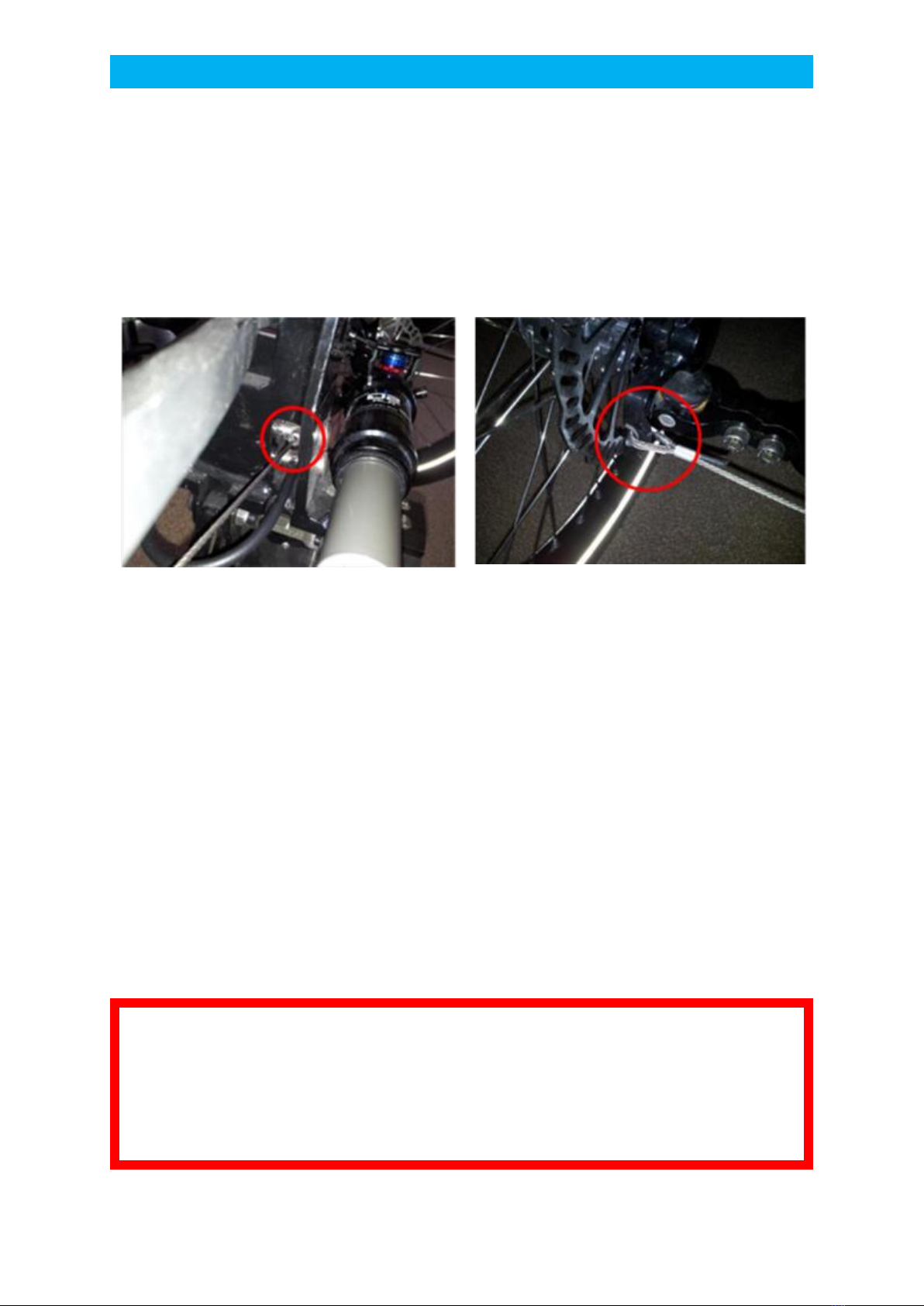
To ensure the full technical functionality of the steering system, the condition of the cable and, the
axle arm and all other parts connected to the steering system have to be checked regularly. The whole
cable should be checked for signs of damage. The most important areas to check are shown in the
images below.
image 4-13: Rear steering cable by swivel bearing
image 4-14: Cable connection front attached to axle arm
The steering cable, even single braids, may not show any signs of damage. If a damage of the steering
cable (broken braids) is visible, the cable has to be replaced immediately. The cable has to be
exchanged by a specialist, e.g. the bike shop where you bought the Veleon. Pay attention to the service
manual of the steering system.
If the tension of the steering cable significantly increases when Veleon is tilted one way or the other,
the steering system should be checked by a specialist. The reason for this can be a deformation at the
axle arm, caused by overstress.
Even if the driving behavior is not negatively influenced, the steering system has to be repaired by a
specialist. If the steering system is not repaired, the cable can take severely damage due to the highly
increased stress, ultimately resulting in a failure of the steering.
The steering cable should be completely changed for safety reasons every two years, even if no visible
damage occurs.
•The correct cable tension is crucial for the longevity and security of the
steering system!
•The steering cable has to be checked for signs of damage on a regular
basis! If the cable is damaged, it has to be replaced immediately!
•The steering cable has to replace every two years.
Table of contents
Popular Bicycle manuals by other brands

Rocky Mountain
Rocky Mountain Element Carbon Platform Manual

Cube
Cube SUPER HPC Additional operating instructions

Yeti Cycles
Yeti Cycles 2011 ARC owner's manual

Coleman Powersports
Coleman Powersports DT200 Assembly instructions

Himiway
Himiway ESCAPE owner's manual

Derby cycle
Derby cycle PEDELEC IMPULSE 2.0 ERGO user manual


