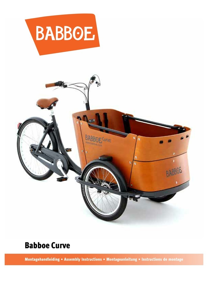
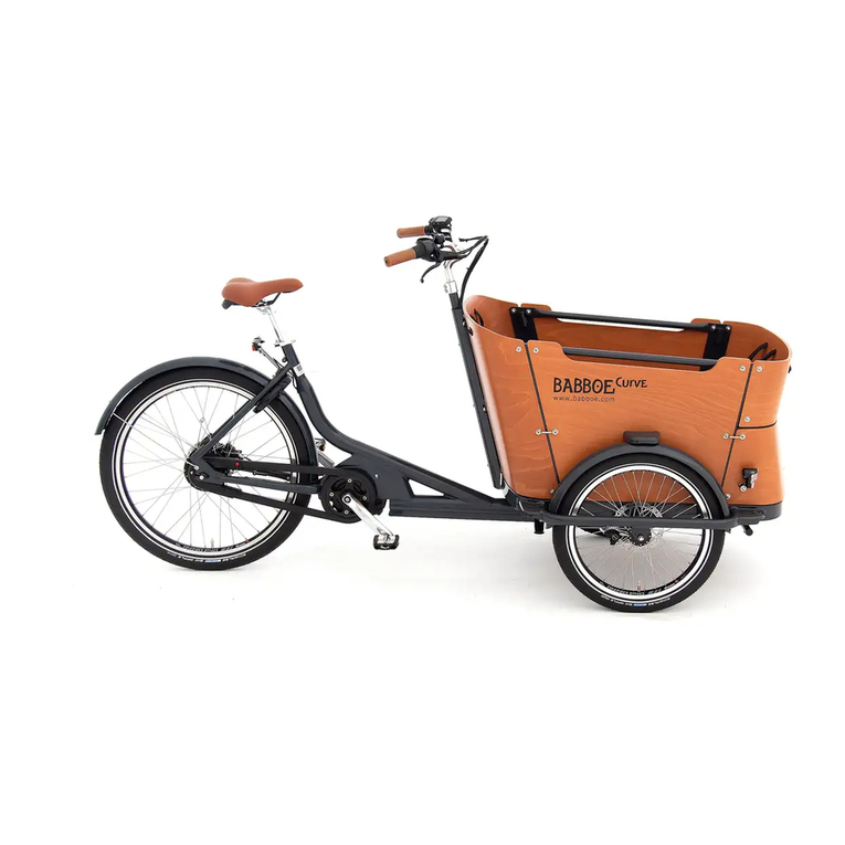
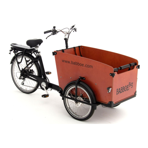
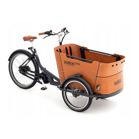
Babboe Curve Installation guide

A
s
s
e
m
b
l
y
I
n
s
t
r
u
c
o
n
M
a
n
u
a
l
B
a
b
b
o
e
C
u
r
v
e
www.bakfietsen.com or your local Babboe website

2
Contents
Intro 3
Inspec on Warnings 4
Inspec on Box I, II and III 5
Inspec on Tools and Instruc ons 6
Step 1: A aching the fenders 7
Step 2: Moun ng the front wheels 8
Step 3: Connec ng the front and rear frame 10
Step 4: A aching the steering damper 12
Step 5.1: Moun ng the steering tube 13
Step 5.2: Securing the steering stem 14
Step 5.3: A aching the saddle 16
Step 6: A aching the brake cables 17
Step 7.1: A aching the bo om plate 20
Step 7.2: A aching the rear panel 21
Step 7.3: A aching the connec on profi les (rear) 22
Step 7.4: A aching the side panels 23
Step 7.5: A aching the steps to the side panels 24
Step 7.6: A aching the connec on profi les (front) 25
Step 7.7: A aching the bo om sec on of the front panel 26
Step 7.8: A aching the top sec on of the front panel 28
Step 8.1: Installing the cargo box seats 29
Step 8.2: A aching the seat belts 32
Step 8.3: A aching the bars inside the cargo box 33
Step 9: A aching the pedals 34
Step 10: A aching the front lights 35
Step 11: Assembling the lock 36
! Tips for use 37
! Warranty 38
! Maintenance history 39

3
Intro
Congratula ons on the purchase of your Babboe Curve cargo bike. This instruc on
manual will assist you with the assembly of the bike. Inspect the contents of the
boxes, make sure that you have the right tools at hand and carefully follow the
steps in this manual. Soon you will be able to enjoy riding your Babboe Curve! This
manual also provides informa on about the use of the Babboe Curve bike and the
warranty.
Front wheels: 20-inch
Rear wheel: 26-inch
Total length: 215 cm
Width: 88 cm
Important! Make sure that you do not begin assembling the Babboe Curve
bike inside the house –the Babboe Curve can fi t through (outside) doors that
are 90 cm wide, but generally cannot fi t through inside doors (which are
typically 80 cm wide).
We hope you will enjoy your new bike!
Babboe Customer Service department
For questions please contact your
local Babboe distributor, contact
details can be found on
www.bakfietsen.com.
If you do not find the right contact details, please contact Babboe in the
Netherlands via [email protected] or give us a call on +31.33.7410742.
!

4
Inspec on Warnings
Warning! Always s ck to the specifi ed order for bolts, nuts and washers in
order to secure everything in the best possible way. Incorrect assembly can
lead to safety risks.
Important! The le and right sides of the bike are shown in this manual as
they would be seen by you if you were si ng on the bike facing forward.
If you have any questions or comments regarding the assembly of the Babboe
Curve cargo bike, please contact your local Babboe distributor. Contact details can
be found on www.bakfietsen.com.
If you do not find the right contact details, please contact Babboe in the
Netherlands via [email protected] or give us a call on +31.33.7410742.
To simplify assembly, we have classifi ed the instruc ons into separate steps. For
each step:
• the bike sec on involved is clearly indicated
• the required tools and parts are clearly specifi ed
• if applicable, the correct order for assembly of bolts, nuts and washers is
illustrated
If the steps in this manual are followed, the full warranty will be in effect as
provided by the local Babboe distributor. Check www.bakfietsen.com for the
specific contact details. Proper assembly of this cargo bike is of crucial
importance and does not fall under the responsibility of Babboe BV. Babboe BV
shall not accept any liability for incorrect assembly nor for any consequences
resulti ng therefrom.
!
!

5
Inspec on Box I, II and III
Inspect the contents of boxes I, II and III.
Note: The contents of the boxes have been carefully determined. Should any parts
be missing a er all, please contact Babboe’s Customer Service department.
Tips to consider before assembly:
Important! When cu ng open the boxes with a knife, be careful not to
damage the parts inside.
Tip: Cut open and fold out the boxes on the ground to use as a surface on
which to assemble the bike.
Tip: Have a garbage bag at hand for disposing of the protec ve packaging
material and other debris.
Tip: Use a plas c container to empty the sachets of nuts, bolts and washers
into.
Box I contents (hwwx-991)
• Front frame
• 2 front wheels (20-inch)
• 2 fenders
• 2 steps
• 2 bars for in the cargo box
Box II contents (hwwx-990)
• Rear frame incl. rear wheel (26-inch)
• Box with saddle, saddle pin, pair of
pedals and rubber strip
• Box with the profi les for a aching
the cargo box
• Box with:
• Tool set
• 4 sets of seat belts
• A achment fi ngs for the seats
• 2 front lights
• Sachets A through N
Box III contents (hwwx-922)
• Panels for the cargo box:
• 2 sec ons for the front panel
• Rear panel
• Bo om panel
• Side panel (le )
• Side panel (right)
• 2 seats
!
!
!
!

6
Inspec on Tools and Instruc ons
Tools needed
Important! A simple, light-duty tool set comes with the cargo bike in the event
that you do not have the required tools at your disposal (except for the Philips
screwdriver or the Bahco key).
Note: In order to
indicate the proper
order of assembly
for bolts, nuts and
washers etc., this
manual will contain
fi gures like the
one shown here
throughout the
manual.
Ring/open-ended spanners # 8-10-11-13-15-30
Allen keys 5-6 mm
Philips screwdriver (Philips 3)
Bahco/ Adjustable spanner (op onal)
!
Bolt
Ring
Ring
Spring washer
Nut

7
Step 1: A aching the fenders
1. Get the front frame and fenders out of the box and remove the protec ve
packaging and materials.
2. Carefully place the front frame onto the central axis of the frame.
(See Figure 1)
3. A ach both fenders to the underside of the front frame, as illustrated in detail
picture A, using two M5 bolts, washers and spring washers from sachet A for
each fender.
4. A ach both steps to the tops of the fenders, as illustrated in detail picture B,
using the two M6 bolts, washers and spring washers from sachet A.
Parts needed:
- 2x fenders (Box I)
- 2x steps to be mounted on the fenders (Box I)
- Front frame (Box I) - Sachet A (4x M5 bolts, 4x M5 spring washers, 4x M5 washers,
2x M6 bolts, 2x M6 spring washers, 2x M6 washers)
Tools needed:
- Philips screwdriver
1.
A.
B.

8
Step 2: Moun ng the front wheels
1. Remove the two nuts/washers from the wheel axle. You will need these again
soon, so keep them at hand.
2. Gently place the front frame on its side.
3. Place the wheel into the front frame as shown in Figure 3. Make sure that
the protruding end of the brake lever/hub fi rst falls into the corresponding
a achment ring (see detail picture C).
!
Important! This a achment point is located in diff erent places on the two
wheels, so the braking mechanism is always situated to the le of the wheel
axle.
Parts needed:
- 2x front wheels (20-inch) (Box I)
Tools needed:
- Open-end spanner # 15
2.
C.

9
4. Screw the nuts back into the wheel axle. Use an open-end spanner to ghtly
secure the nuts (see detail picture D).
5. Repeat the previous steps for the other wheel.
D.
3.

10
Step 3: Connec ng the front and rear frame
Note: Ask for assistance from someone for this step. It will be a lot easier if you do.
1. Get the rear frame out of the box and remove the protec ve packaging
materials.
2. Posi on the front frame onto the wheels, allowing it to rest on the lt guards.
3. The rear frame includes an a achment piece with a large bolt (see Fig. 4). This
bolt has been pre- ghtened for transport purposes only; remove the bolt.
Keep the removed bolt, nut and washer at hand for later.
Parts needed:
- The rear frame (Box II)
- The front frame
Tools needed:
- Open-end spanner # 30 /
Bahco / adjustable spanner
4.

11
4. Slide the a achment piece over the cylinder onto the front frame as shown in
Figure 5.
5. Then place the washers (5) between the a achment piece (1) and the cylinder
(2) as shown in Figures 6 and 7. Then re-insert the bolt (3) through the
a achment piece and the cylinder.
6. Next, fi t the nut (4) onto the bolt and use a # 30 open-end spanner or a Bahco
hex key to screw it as ghtly as possible. A blockage at the top (head) of the
bolt means that it will stay in place when screwing the nut on (you don’t have
to hold the bolt head in place).
5.
6.
2
1
3
4
5
5
5
7.

12
Step 4: A aching the steering damper
This step involves a achment of the steering dampers. These are already pre-
mounted onto the rear frame (see Figure 8).
1. Remove the specifi ed (1)
nuts and bolts from the
steering dampers (2). Keep
the removed nuts, bolts and
washers at hand for later.
2. Next, extend the damper so
the a achment hole of the
damper lines up with the
a achment hole in the front
frame (see Fig. 9).
3. Securely a ach the dampers
to the front frame using the
nuts, bolts and washers from
earlier (see Figure 9 for the
correct order).
Tools needed:
- Open-end spanner # 13
- Allen key # 6
2
8.
9.

13
Step 5.1: Moun ng the steering tube
The steering tube is mounted onto the front frame during this step. The steering
tube is already connected to the rear frame by means of the gear and brake cable.
1. Posi on the steering tube against the front frame as shown in Figure 10.
2. Insert the two M8 bolts into the a achment holes. Screw on and fi rmly
ghten the nuts to the underside. If this is problema c, gently tap the bolt
through the hole with a hammer or the handle of a screwdriver.
Important! Adhere to the correct order for the nut, bolt and washers in order
to secure everything in the best possible way (see detail picture E).
Parts needed:
- Sachet B (2x M8 bolts, 2x M8 lock nuts, 4x M8 washers)
Tools needed:
- Open-end spanner # 13
- Allen key # 5
10.
E.
!

14
Step 5.2: Securing the steering stem
The stem is already inserted into the steering tube, but s ll has to be adjusted and
secured into the correct posi on.
Tip: Only adjust the posi on of the steering stem loosely at this point; you will
determine the defi nite posi on later on during assembly. Also ghten the
Allen (hex) bolts at the top of the steering tube.
1. Unscrew the Allen (hex) bolt at the top of the steering pin using Allen key # 5
(see Figure 11).
2. Set the steering stem/handlebars to an appropriate posi on.
3. Hand- ghten the stem/handlebars by re ghtening the Allen (hex) bolt at the
top of the steering pin.
Tools needed:
- Allen keys # 5 and 6
11.
!

15
1. If you want to adjust the angle of the stem, un ghten the two hex bolts at the
front of the steering pin using Allen key # 6 (see Figure 12).
2. Set the stem to the desired posi on and then re ghten the hex bolts.
12.

16
Step 5.3: A aching the saddle
Important! Adhere to the specifi ed order of sub-steps for this part of the
assembly. If you a ach the saddle pin fi rst, you run the risk of the saddle pin
falling down into the saddle tube. Therefore, make sure to start with a aching
the saddle onto the saddle pin fi rst.
For the sake of the steps to follow, it is useful to secure the saddle now (fi nal
posi oning will take place a er the assembly is fi nished).
1. A ach the saddle to the
narrow end of the separate
saddle pin using open-end
spanner # 13 (see Fig. 13).
The a achment fi ngs are
already fi ed to the underside
of the saddle (see detail
picture F).
2. Slide the saddle pin into the
saddle tube approximately up
to the desired height (see Fig.
14). Hand-secure the saddle
pin by ghtening the hex bolt
at the top of the saddle tube
(see detail picture G).
Parts needed:
- Saddle and saddle pin
Tools needed:
- Open-end spanner # 13
- Allen key # 5
13.
F.
14.
G.
!

17
Step 6: A aching the brake cables
The front brake cables are the only cables that have not been fully pre-mounted.
These cables have been pre-mounted onto the steering stem (handlebars), but s ll
have to be a ached at the wheels.
1. First, guide a cable from the le brake lever on the handlebars via the guide
points on the le side of the steering tube and the underside of the front
frame (indicated with arrows in Figure 15) to the le front wheel. Insert the
inner cable (2) through the slot in the guide point (1) on the underside of
the front frame. Next, also guide the outer cable (3) through here (see detail
picture H).
1
3
2
15.
H.

18
2 Insert the cap on the end of the steel
brake cable into the upper brake lever,
as shown in Figures 16 and 17.
3. Place the brake cable into the groove
of the brake (indicated with arrows in
Fig. 18).
16.
17.
18.
19.

19
2 Insert the cap on the end of the steel
brake cable into the upper brake lever,
as shown in Figures 16 and 17.
3. Place the brake cable into the groove
of the brake (indicated with arrows in
Fig. 18).
16.
17.
18.
19.
4. Next, hook the cable around the
noodle (indicated with an arrow in
Fig. 19).
5. Then li the lower lever up to
a ach the last adjustment clamp
there (see Fig. 20).
The brake cable is now installed
(see Fig. 21).
6. Repeat these steps for the right
front wheel and the right brake
cable.
Important! The brake cable should be properly adjusted by the manufacturer
on delivery. If this is not the case, adjust the adjustment clamps at the
handlebars or at the brake lever on the front wheel.
20.
21.
!

20
Step 7.1: A aching the bo om plate
Step 7 involves moun ng the cargo box. This step is divided into a number of
sub-steps. These will be described in the following sec ons. For all the steps
for moun ng the cargo box, all of the nuts and bolts must be hand- ghtened
(temporarily secured). Everything will be properly ghtened and secured once the
cargo box is complete. This will allow the cargo box to be properly posi oned for
op mum comfort and use.
1. Place the bo om plate on the front frame as shown in Figure 22 and mount
the bo om plate onto the frame using the nuts, bolts and washers from
sachet C.
Important! Adhere to the specifi ed order for nuts, bolts and washers in order
to secure everything in the best possible way (see detail picture I).
Parts needed:
- Bo om plate (found in the bo om of Box III)
- Sachet C (4x M6 bolts, 4x M6 cap nuts, 4x M6 spring washers,
8x M6 washers)
Tools needed:
- Open-end spanner # 10
- Philips screwdriver
22.
I.
!
Other manuals for Curve
6
Table of contents
Other Babboe Bicycle manuals

Babboe
Babboe City User manual

Babboe
Babboe Mini Mountain User manual

Babboe
Babboe Carve Mountain User manual

Babboe
Babboe City User manual

Babboe
Babboe Curve Mountain User manual

Babboe
Babboe curve-e User manual

Babboe
Babboe Curve Installation guide

Babboe
Babboe Carve-E User manual

Babboe
Babboe Curve User manual

Babboe
Babboe Big User manual