manuals.online logo
Brands
  1. Home
  2. •
  3. Brands
  4. •
  5. Harris
  6. •
  7. Transmitter
  8. •
  9. Harris MW-5 Reference manual

Harris MW-5 Reference manual

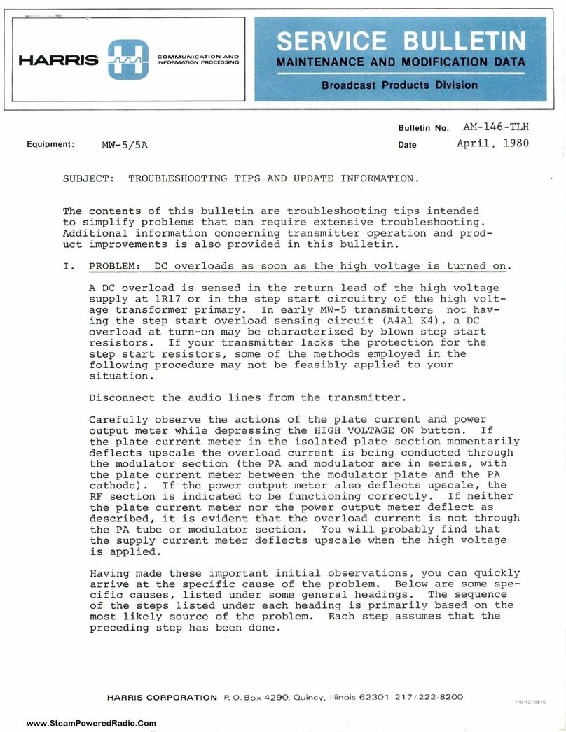
www.SteamPoweredRadio.Com
HARRIS
~I
COMMUN
I
CATIONS
AND
IN
FORMAT
I
ON
HANDLING
Equipment:
MW-5
A.M
Transmitter
MAINTENANCE AND MODIFICATION DATA
Broadcast Products Division
A."1-109-KDL
Bulletin
No.
Date
October
2
5,
197
6
Subject:
Additional
Maintenance
and
Troubleshooting
Information
A.
Neutralization:
The
MW-5
should
not
require
frequent
neutralization,
but
in
the
event
of
any
component
failure
in
the
PA
grid
or
plate
circuits,
the
neutralization
should
be
checked
as
follows:
1.
Measure
the
DC
resistance
of
the
resistors
used
as
grid
(1A3Zl)
and
plate
(lZl)
parasitic
suppressors.
An
open
parasitic
suppression
resistor
can
upset
circuit
stability
and
make
neutralization
difficult.
These
failures
are
often
not
detectable
visually.
2.
Disconnect
the
center
lead
of
the
coaxial
cable
attached
to
the
PA
grid
transformer
input
tuning
capacitor
(1A3Cl2),
located
on
the
center
side
wall
of
the
PA
grid/cathode
cavity.
Connect
an
RF
signal
generator
(previously
zero-
beated
with
the
transmitter
oscillator
or
adjusted
to
assigned
carrier
frequency
using
a
counter)
between
capacitor
input
lug
and
ground.
Connect
an
oscilloscope
having
at
least
a 5MHz.
vertical
bandwidth
between
tube
plate
and
ground.
3.
WITH
NO
AC
POWER
APPLIED
TO
THE
TRANSMITTER,
adjust
the
~
generator
output
level
and
'scope
vertical
gain
for
a
convenient
display.
Adjust
neutralization
padder
capacitor
1A3C3
for
minimum
signal
amplitude.
4.
Check
the
degree
of
mesh
of
the
plate
of
1A3C3.
If
1A3C3
is
fully
open
or
fully
meshed,
the
neutralization
procedure
is
not
yet
finished.
Should
a
reasonable
amount
of
mesh
exist,
neutralization
is
complete.
5.
On
original
MW-Ss
(shipped
prior
to
October,
1976),
the
center
tap
on
PA
grid
transformer
1A3Tl
is
moved
one
turn
at
a
time
until
minimum
signal
amplitude
and
within-range
mesh
of
the
plates
of
1A3C3
is
obtained.
6.
On
later
MW-Ss
(identified
by
the
presence
of
grid
bias
RF
choke
1A3L2),
the
value
of
1A3Cll
or
1A3C10
may
have
to
be
changed
to
achieve
within-range
mesh
of
1A3C3.
HARRIS
CORPORATION
1
23
H
ampsh
ir
e
St
r
eet
,
Quincy
,
Illin
ois
62301
21
7 /
222-8200
www.SteamPoweredRadio.Com
-2-
7.
If
proper
neutralization
cannot
be
achieved,
failure
of
neutralization
blocker
capacitors
1A3C9
and/or
Cl0
or
grid
transformer
secondary
tuning
capacitors
lA3ClA,B,
etc.
should
be
investigated.
8.
When
adjustments
are
completed,
be
sure
to
remove
all
test
equipment
from
the
transmitter
and
restore
connection
of
the
RF
driver
output
cable
center
conductor
to
1A3Cl2.
9.
Restore
transmitter
operation
at
full
carrier
power
and
perform
normal
tuning
procedures
as
necessary.
B.
Checking
of
Grid
and
Plate
Efficiency
Resonators:
Poor
efficiency,
wierd
tuning,
excessive
audio
distortion,
excessive
RF
harmonic
output,
and
other
operational
instabil-
ities
may
be
caused
by
mis-adjusted
or
faulty
efficiency
reson-
ators.
When
these
symptoms
are
present,
the
resonators
must
be
thoroughly
examined
and
carefully
adjusted.
1.
Perform
the
adjustment
procedure
outlined
in
sections
4.3(17)
through
(19)
on
page
4-6
of
the
MW-5
Instruction
Book.
If
tuning
and
operation
still
does
not
seem
normal
or
an
obvious
component
failure
has
occurred,
further
effort
is
required.
2.
Drop
a
small
oscilloscope
probe
(connected
to
the
'scope
vertical
input)
through
the
grating
above
the
PA
tube
and
connect
the
ground
clip
to
the
grating.
Observe
the
PA
plate
waveform
at
an
RF
sweep
rate.
It
should
look
something
like
that
shown
below
if
operation
is
normal.
www.SteamPoweredRadio.Com
-3-
3.
Find
the
setting
of
the
resonators
by
the
following
method:
Set
up
an
RF
generator,
clip
leads,
resistors,
and
the
'scope
as
shown
in
the
diagrams
below.
Vary
generator
frequency
until
a
response
peak
is
noted;
determine
the
generator
frequency
at
that
point.
It
should
be
within
±200kHz.
of
the
third
harmonic
of
the
assigned
carrier
frequency.
If
not,
adjust
the
generator
to
the
third
harmonic
and
adjust
the
resonator
for
a
response
peak.
In
the
case
of
the
grid
resonator,
it
may
be
necessary
to
change
the
tap
on
coil
1A3Ll
one
turn
either
way
to
place
grid
efficiency
tuning
capacitor
1A3C2
within
range.
General
Test
Circuit:
RF
Generator
lK
47
to
56
ohms
r :
Test
--,
+
Point
"A"
'Scope
----
C
----------,--------
Test
Point
"B"
Transmitter
Chassi
s
Plate
Resonator
Connections:
1Cl2
o,-----;1--
1Cl3
Test
Point
"A"
Grid
Resonator
Connections:
Test
Points
"A
II
"B"
*all
components
have
1A3
prefix
for
grid
circuit
www.SteamPoweredRadio.Com
4.
-4-
Repeat
the
efficienc
y
optimization
procedure
of
sect
i
ons
4.3(17)
through
(19)
on
page
4-6
of
your
Instruction
Book.
A
waveform
similar
to
that
in
(2)
above
sh
ould
now
be
noted
.
C.
Optimization
of
.
Harmonic
Distortion
A
sys
t
ematic
procedure
of
adjustment
will
lead
to
reduction
in
audio
distortion
products
generated
by
the
transmitter.
1.
Adjust
plate
tuning,
efficiency
resonator,
grid
tuning,
and
grid
efficiency
resonator
with
no
modulation
in
accordance
with
the
procedure
outlined
in
sections
4.3(16)
through
(19)
of
your
Instruction
Book.
2.
Modulate
the
transmitter
into
the
normal
load
(antenna)
to
95%
positive
or
negative
(whichever
co
mes
first)
at
400
Hz.
Measure
and
note
harmonic
distortion
(T.H.D.).
3.
Adjust
the
following
controls
for
minimum
T.H.D.:
a.
Modulator
high-power
screen
voltage
-
1A4Rl0
b.
Auxiliary
modulation
-
1AlR3
c.
Auxiliary
driver
-
1AlA3R8
Several
repetitions
of
the
adjustment
cycle
above
may
be
necessary
to
assure
a
distortion
null.
4.
Change
audio
generator
frequency
to
SkHz
•·
and
modulate
the
transmitter
to
95%
positive.
Measure
and
note
T.H.D.
and
PA
plate
tuning
control
dial
counter
reading.
Adjust
the
PA
plate
tuning
control
for
minimum
T.H.D.
and
note
both
distortion
and
dial
counter
readings.
Back
off
the
PA
tuning
until
the
halfway
point
between
the
two
distortion
values
or
dial
counter
readings
is
reached.
Then
adjus
t
the
PA
plate
efficiency
resonator
for
minimum
T.H.D.
5.
Return
to
400Hz.
at
95%
modulation
and
repeat
step
(2)
above.
Note
distortion
with
modulating
frequencies
of
400Hz.,
lkHz.,
2.SkHz.,
and
SkHz.
6.
It
may
be
possible
to
further
reduce
T.H.D.
at
SkHz.
through
adjustment
of
the
Auxiliary
Modulation
control.
However,
this
control
will
not
show
a
T.H.D.
null
at
high
audio
frequencies.
It
reduces
T.H.D.
to
a
minimum
value
and
further
rotation
of
the
control
will
not
change
T.H.D
.
The
auxiliary
modulation
control
should
be
adjusted
to
t he
poi
nt
where
T.H.D.
is
just
on
the
verge
of
increasing.
Dist
o
rtion
should
be
checked
once
again
at
400Hz.
and
compared
with
previous
results.
In
some
transmitters,
a
slight
trade-off
between
mid-band
and
high-frequency
T.H.D
.
is
necessary.
This
trade-off
should
not
typically
increa
se
mid-band
T.H.D.
more
than
0.2%
in
order
to
achieve
in-s
p
ec.
high
frequency
harmonic
distortion.
www.SteamPoweredRadio.Com
-5-
7.
A
slight
adjustment
of
the
grid
efficiency
resonator
may
lower
T.H.D.
slightly
in
older
MW-Ss.
Should
you
find
this
to
be
the
case
in
your
transmitter,
leave
the
resonator
set
just
to
the
verge
of
causing
a
T.H.D.
increase.
In
no
case
should
the
PA
plate
voltage
be
all0wed
to
increase
more
than
50
volts
(½
division)
above
the
dip
obtained
in
(1).
8.
Harmonic
distortion
problems
at
high
audio
frequencies
are
many
times
the
result
of
asymmetrical
or
reactive
antenna
sideband
impedances.
Transmitters
are
designed
by
all
manufacturers
around
an
industry
standard
for
a
"normal
load".
This
EIA
specification
calls
for
the
reactive
component
of
the
load
im
p
edance
to
be
adjusted
to
zero
at
the
transmitter
output
terminals
for
operation
at
assigned
carrier
frequency.
The
resistive
component
of
load
impedance
may
not
vary
more
than
±5%
of
the
carrier
frequency
resistance
value
at
sideband
frequencies
through
5kHz.
either
side
of
carrier.
The
reactive
components
cannot
exceed
±18%
of
the
carrier
resistive
value
over
the
same
frequency
range.
From
5kHz.,
through
l0kHz.
sidebands,
the
resistive
component
must
be
within
±10%
of
carrier
resistive
value
and
the
reactive
component
must
be
within
±35%
of
carrier
resistive
value.
9.
Old
modulator
tubes
and
PA
tubes
may
sometimes
affect
distortion
figures.
Also,
an
open-delta
AC
primary
power
source
will
cause
low-frequency
distortion
problems
.•
If
T.H.D.
problems
exist
at
low
frequencies
{less
than
l00Hz.)
only,
keep
in
mind
that
the
transmitter
was
designed
for
connection
to
a
closed-delta
power
source
{as
spelled
out
in
the
instruction
book).
Take
appropriate
action
to
assure
a
closed-delta
AC
primary
power
source.

Other manuals for MW-5

1

Other Harris Transmitter manuals

Harris MW-1 Reference manual

Harris

Harris MW-1 Reference manual

Harris Platinum Z2 CD User manual

Harris

Harris Platinum Z2 CD User manual

Harris Platinum Z16HD+ User manual

Harris

Harris Platinum Z16HD+ User manual

Harris GATES FM-3H User manual

Harris

Harris GATES FM-3H User manual

Harris MW-SB User manual

Harris

Harris MW-SB User manual

Harris SX-1 User manual

Harris

Harris SX-1 User manual

Harris GATES FM-20H3 User manual

Harris

Harris GATES FM-20H3 User manual

Harris Z3-48HD+ User manual

Harris

Harris Z3-48HD+ User manual

Harris GATES M-6576 User manual

Harris

Harris GATES M-6576 User manual

Harris HTlFM User manual

Harris

Harris HTlFM User manual

Harris MW-1 Manual

Harris

Harris MW-1 Manual

Harris DiamondCD Series User manual

Harris

Harris DiamondCD Series User manual

Harris eCDi User manual

Harris

Harris eCDi User manual

Harris Platinum Series User manual

Harris

Harris Platinum Series User manual

Harris Micromax User manual

Harris

Harris Micromax User manual

Harris MW-5 Reference manual

Harris

Harris MW-5 Reference manual

Harris SX-1 User manual

Harris

Harris SX-1 User manual

Harris Platinum HT EL 2000LS User manual

Harris

Harris Platinum HT EL 2000LS User manual

Harris Maxiva ULX COFDM Series User manual

Harris

Harris Maxiva ULX COFDM Series User manual

Harris ATLAS ANALOGUE User manual

Harris

Harris ATLAS ANALOGUE User manual

Harris Ranger Series Quick start guide
Harris

Harris Ranger Series Quick start guide

Harris DX 25U User manual

Harris

Harris DX 25U User manual
Harris FM-10H3 User manual

Harris

Harris FM-10H3 User manual

Harris 994 8047 001 User manual

Harris

Harris 994 8047 001 User manual

Popular Transmitter manuals by other brands
Microgate Hilink user manual

Microgate

Microgate Hilink user manual

PureLink HTR Tx owner's manual

PureLink

PureLink HTR Tx owner's manual

IDFone VLP2 user manual

IDFone

IDFone VLP2 user manual

Fly Sky FS-i6 programming

Fly Sky

Fly Sky FS-i6 programming

AVLink BTTR1 user manual

AVLink

AVLink BTTR1 user manual

Black Box AC1003A-R2 quick start guide

Black Box

Black Box AC1003A-R2 quick start guide

GiBiDi DRS4333-RX ESTERNO A-NOX 2CH CA quick start guide

GiBiDi

GiBiDi DRS4333-RX ESTERNO A-NOX 2CH CA quick start guide

Delta OHM PMsense operating manual

Delta OHM

Delta OHM PMsense operating manual

Entrematic ZEN Series user manual

Entrematic

Entrematic ZEN Series user manual

Cine Gears Ghost-Eye 800TC Manual book

Cine Gears

Cine Gears Ghost-Eye 800TC Manual book

Black Box IC447A user manual

Black Box

Black Box IC447A user manual

NOSHOK PT41 Series user manual

NOSHOK

NOSHOK PT41 Series user manual

Camsat CDS-5IPmini Quick start-up

Camsat

Camsat CDS-5IPmini Quick start-up

Dynalab SWTD-1000 operating manual

Dynalab

Dynalab SWTD-1000 operating manual

SMART-AVI XT-TX400 quick start guide

SMART-AVI

SMART-AVI XT-TX400 quick start guide

Honeywell SmartLine ST 800 user manual

Honeywell

Honeywell SmartLine ST 800 user manual

Marti STL-15C instruction manual

Marti

Marti STL-15C instruction manual

M-system 10VK instruction manual

M-system

M-system 10VK instruction manual

manuals.online logo
manuals.online logoBrands
  • About & Mission
  • Contact us
  • Privacy Policy
  • Terms and Conditions

Copyright 2025 Manuals.Online. All Rights Reserved.