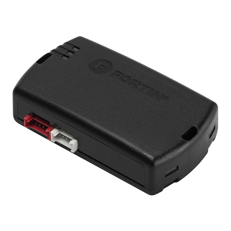
ADS iDatalink START IB User manual

NOTICE
The manufacturer will accept no responsability for any electrical damage resulting from
improper installation of this product, be that either damage to the vehicle itself or to the
installed device. This device must be installed by a certified technician. This guide has been
written for properly trained technicians; a certain level of skill & knowledge is therefore
assumed. Please review the Installation Guide carefully before beginning any work.
REvIsION DaTE
20121002
DOCumENT NumbER
INsTall guIDE
SIBKEYNI4EN
haRDwaRE
STARTIB
fIRmwaRE
SIBKEYNI4
www.idatalink.com/ruAutomotive Data Solutions Inc. © 2012
10554

vEhIClE lIsT - 1 Of 2
maKE
mODEl
YEaR
INsTall TYPE
fEaTuREs
DaTa ImmObIlIZER bYPass
INfINITI
FX35 Intelli-key 05-08 2 •
FX35 Regular key 05-08 1 •
FX45 Intelli-key 05-08 2 •
FX45 Regular key 05-08 1 •
G35 Coupe Regular key 05-07 1 •
G35 Intelli-key 05-09 2 •
G35 Sedan Regular key 05-06 1 •
QX56 Intelli-key 08-10 2 •
QX56 Regular key 05-09 1 •
NIssaN
350Z Regular key 06-09 1 •
Altima Regular key 05-06 1 •
Armada Intelli-key 08-12 2 •
Armada Regular key 05-12 1 •
Cube Regular key 09-12 1 •
Frontier Regular key 05-12 1 •
Juke Regular key 11-12 1 •
Maxima Intelli-key 07-08 2 •
Maxima Regular key 04-08 1 •
Pathfinder Intelli-key 08-12 2 •
Pathfinder Regular key 05-12 1 •
Quest Regular key 04-09 1 •
Rogue Intelli-key 08-12 2 •
Rogue Regular key 08-12 1 •
Sentra Intelli-key 07-12 2 •
Sentra Regular key 07-12 1 •
Titan Regular key 05-12 1 •
www.idatalink.com/ruAutomotive Data Solutions Inc. © 2012 SIBKEYNI4EN
PagE 2 Of 16
• 20121002
DOC.: #10554

vEhIClE lIsT - 2 Of 2
maKE
mODEl
YEaR
INsTall TYPE
fEaTuREs
DaTa ImmObIlIZER bYPass
NIssaN
Versa Hatchback Regular key 12 1 •
Versa Intelli-key 07-11 2 •
Versa Regular key 07-11 1 •
Versa Sedan Regular key 12 1 •
Xterra Regular key 05-12 1 •
suZuKI
Equator Regular key 09-11 1 •
www.idatalink.com/ruAutomotive Data Solutions Inc. © 2012 SIBKEYNI4EN
PagE 3 Of 16
• 20121002
DOC.: #10554

TYPE 1 - wIRE ChaRT - 1 Of 5
maKE
mODEl
YEaR
wIRE
DEsCRIPTION
CONNECTOR
POsITION
wIRE
COlOR
POlaRITY
mODulE
lOCaTION
COmPONENT
lOCaTOR
NamE
COlOR
TYPE
INfINITI
FX35 Regular key 05-08
Immobilizer clock M25 White 04 pin 02 Green/Black (DATA) Immobilizer next to ignition switch ~
Immobilizer data M25 White 04 pin 04 Brown (DATA) Immobilizer next to ignition switch ~
12V E252 White 06 pin 01 Blue/Red (+) Ignition switch ~
Accessory E252 White 06 pin 04 White (+) Ignition switch ~
Ignition E252 White 06 pin 05 Black (+) Ignition switch ~
Starter 1 E252 White 06 pin 03 Blue (+) Ignition switch ~
Starter 2 E252 White 06 pin 02 Pink (+) Ignition switch ~
FX45 Regular key 05-08
Immobilizer clock M25 White 04 pin 02 Green/Black (DATA) Immobilizer next to ignition switch ~
Immobilizer data M25 White 04 pin 04 Brown (DATA) Immobilizer next to ignition switch ~
12V E252 White 06 pin 01 Blue/Red (+) Ignition switch ~
Accessory E252 White 06 pin 04 White (+) Ignition switch ~
Ignition E252 White 06 pin 05 Black (+) Ignition switch ~
Starter 1 E252 White 06 pin 03 Blue (+) Ignition switch ~
Starter 2 E252 White 06 pin 02 Pink (+) Ignition switch ~
G35 Coupe Regu-
lar key 05-07
Immobilizer clock M308 White 04 pin 02 Green (DATA) Immobilizer next to ignition switch ~
Immobilizer data M308 White 04 pin 04 Brown (DATA) Immobilizer next to ignition switch ~
12V M306 White 06 pin 01 White/Blue (+) Ignition switch ~
Accessory M306 White 06 pin 04 White/Black (+) Ignition switch ~
Ignition M306 White 06 pin 05 Black/Red (+) Ignition switch ~
Starter 1 M306 White 06 pin 03 White/Red (+) Ignition switch ~
Starter 2 M306 White 06 pin 02 White/Green (+) Ignition switch ~
G35 Sedan Regu-
lar key 05-06
Immobilizer clock M308 White 04 pin 02 Green (DATA) Immobilizer next to ignition switch ~
Immobilizer data M308 White 04 pin 04 Brown (DATA) Immobilizer next to ignition switch ~
12V M306 White 06 pin 01 White/Blue (+) Ignition switch ~
Accessory M306 White 06 pin 04 White/Black (+) Ignition switch ~
Ignition M306 White 06 pin 05 Black/Red (+) Ignition switch ~
Starter 1 M306 White 06 pin 03 White/Red (+) Ignition switch ~
Starter 2 M306 White 06 pin 02 White/Green (+) Ignition switch ~
QX56 Regular key 05-09
Immobilizer clock M21 White 04 pin 02 Green (DATA) Immobilizer next to ignition switch ~
Immobilizer data M21 White 04 pin 04 Brown (DATA) Immobilizer next to ignition switch ~
12V M26 White 06 pin 01 Green (+) Ignition switch ~
Accessory M26 White 06 pin 06 Red (+) Ignition switch ~
Ignition M26 White 06 pin 05 Black/Red (+) Ignition switch ~
Starter 1 M26 White 06 pin 03 Brown (+) Ignition switch ~
Starter 2 M26 White 06 pin 02 LtGreen (+) Ignition switch ~
www.idatalink.com/ruAutomotive Data Solutions Inc. © 2012 SIBKEYNI4EN
PagE 4 Of 16
• 20121002
DOC.: #10554

TYPE 1 - wIRE ChaRT - 2 Of 5
maKE
mODEl
YEaR
wIRE
DEsCRIPTION
CONNECTOR
POsITION
wIRE
COlOR
POlaRITY
mODulE
lOCaTION
COmPONENT
lOCaTOR
NamE
COlOR
TYPE
NIssaN
350Z Regular key 06-09
Immobilizer clock M28 White 04 pin 02 Green/White (DATA) Immobilizer next to ignition switch ~
Immobilizer data M28 White 04 pin 04 Brown (DATA) Immobilizer next to ignition switch ~
12V E119 White 06 pin 01 Green (+) Ignition switch ~
Accessory E119 White 06 pin 04 White/Black (+) Ignition switch ~
Ignition E119 White 06 pin 05 Black/Red (+) Ignition switch ~
Starter 1 E119 White 06 pin 03 White/Red (+) Ignition switch ~
Starter 2 E119 White 06 pin 02 White/Green (+) Ignition switch ~
Altima Regular
key 05-06
Immobilizer clock M27 White 04 pin 02 Pink (DATA) Immobilizer next to ignition switch ~
Immobilizer data M27 White 04 pin 04 Yellow/Black (DATA) Immobilizer next to ignition switch ~
12V E41 White 06 pin 01 Green (+) Ignition switch ~
Accessory E41 White 06 pin 03 Red (+) Ignition switch ~
Ignition E41 White 06 pin 05 Black/Red (+) Ignition switch ~
Starter 1 E41 White 06 pin 03 Black/Red (+) Ignition switch ~
Starter 2 E41 White 06 pin 02 Black/Yellow (+) Ignition switch ~
Armada Regular
key 05-12
Immobilizer clock M21 White 04 pin 02 Green (DATA) Immobilizer next to ignition switch ~
Immobilizer data M21 White 04 pin 04 Brown (DATA) Immobilizer next to ignition switch ~
12V M26 White 06 pin 01 Green (+) Ignition switch ~
Accessory M26 White 06 pin 06 Red (+) Ignition switch ~
Ignition M26 White 06 pin 05 Black/Red (+) Ignition switch ~
Starter 1 M26 White 06 pin 03 Brown (+) Ignition switch ~
Starter 2 M26 White 06 pin 02 LtGreen (+) Ignition switch ~
Cube Regular key 09-12
Immobilizer clock M26 White 04 pin 02 Pink/Blue (DATA) Immobilizer next to ignition switch ~
Immobilizer data M26 White 04 pin 04 LtGreen (DATA) Immobilizer next to ignition switch ~
12V M29 White 06 pin 01 Blue (+) Ignition switch ~
Accessory M29 White 06 pin 06 Yellow/Black (+) Ignition switch ~
Ignition M29 White 06 pin 05 White/Red (+) Ignition switch ~
Starter 1 M29 White 06 pin 03 White (+) Ignition switch ~
Starter 2 ~ ~ ~ ~ ~ ~ ~ ~
Frontier Regular
key 05-12
Immobilizer clock M21 White 04 pin 02 Gray (DATA) Immobilizer next to ignition switch ~
Immobilizer data M21 White 04 pin 04 Brown (DATA) Immobilizer next to ignition switch ~
12V M26 White 06 pin 01 Green (+) Ignition switch ~
Accessory M26 White 06 pin 06 Red (+) Ignition switch ~
Ignition M26 White 06 pin 05 White/Green (+) Ignition switch ~
Starter 1 M26 White 06 pin 03 Gray (+) Ignition switch ~
Starter 2 ~ ~ ~ ~ ~ ~ ~ ~
www.idatalink.com/ruAutomotive Data Solutions Inc. © 2012 SIBKEYNI4EN
PagE 5 Of 16
• 20121002
DOC.: #10554

TYPE 1 - wIRE ChaRT - 3 Of 5
maKE
mODEl
YEaR
wIRE
DEsCRIPTION
CONNECTOR
POsITION
wIRE
COlOR
POlaRITY
mODulE
lOCaTION
COmPONENT
lOCaTOR
NamE
COlOR
TYPE
NIssaN
Juke Regular key 11-12
Immobilizer clock M26 White 04 pin 02 Pink (DATA) Immobilizer next to ignition switch ~
Immobilizer data M26 White 04 pin 04 LtGreen (DATA) Immobilizer next to ignition switch ~
12V M29 White 06 pin 01 Blue ~ Ignition switch ~
Accessory M29 White 06 pin 06 Yellow (+) Ignition switch ~
Ignition M29 White 06 pin 05 Red (+) Ignition switch ~
Starter 1 M29 White 06 pin 03 White (+) Ignition switch ~
Starter 2 ~ ~ ~ ~ ~ ~ ~ ~
Maxima Regular
key 04-08
Immobilizer clock M21 White 04 pin 02 Pink (DATA) Immobilizer next to ignition switch ~
Immobilizer data M21 White 04 pin 04 Green (DATA) Immobilizer next to ignition switch ~
12V E41 White 06 pin 01 Green (+) Ignition switch ~
Accessory E41 White 06 pin 03 Red (+) Ignition switch ~
Ignition E41 White 06 pin 05 Black/Red (+) Ignition switch ~
Starter 1 E41 White 06 pin 03 Black/Red (+) Ignition switch ~
Starter 2 E41 White 06 pin 02 Black/Yellow (+) Ignition switch ~
Pathfinder Regu-
lar key 05-06
Immobilizer clock M21 White 04 pin 02 Gray (DATA) Immobilizer next to ignition switch ~
Immobilizer data M21 White 04 pin 04 Brown (DATA) Immobilizer next to ignition switch ~
12V M26 White 06 pin 01 Green (+) Ignition switch ~
Accessory M26 White 06 pin 03 Red Or Gray (+) Ignition switch ~
Ignition M26 White 06 pin 05 White/Green (+) Ignition switch ~
Starter 1 M26 White 06 pin 03 Gray (+) Ignition switch ~
Starter 2 M26 White 06 pin 02 LtGreen (+) Ignition switch ~
Pathfinder Regu-
lar key 07-12
Immobilizer clock M21 White 04 pin 02 Gray (DATA) Immobilizer next to ignition switch ~
Immobilizer data M21 White 04 pin 04 Brown (DATA) Immobilizer next to ignition switch ~
12V M26 White 06 pin 01 Green (+) Ignition switch ~
Accessory M26 White 06 pin 03 Red Or Gray (+) Ignition switch ~
Ignition M26 White 06 pin 05 White/Green (+) Ignition switch ~
Starter 1 M26 White 06 pin 03 Gray (+) Ignition switch ~
Starter 2 M26 White 06 pin 02 LtGreen (+) Ignition switch ~
Quest Regular key 04
Immobilizer clock M21 White 04 pin 02 Orange (DATA) Immobilizer next to ignition switch ~
Immobilizer data M21 White 04 pin 04 Brown (DATA) Immobilizer next to ignition switch ~
12V M26 White 06 pin 01 Green (+) Ignition switch ~
Accessory M26 White 06 pin 03 Red (+) Ignition switch ~
Ignition M26 White 06 pin 05 Black/White (+) Ignition switch ~
Starter 1 M26 White 06 pin 03 Black/Red (+) Ignition switch ~
Starter 2 M26 White 06 pin 02 Black/Yellow (+) Ignition switch ~
www.idatalink.com/ruAutomotive Data Solutions Inc. © 2012 SIBKEYNI4EN
PagE 6 Of 16
• 20121002
DOC.: #10554

TYPE 1 - wIRE ChaRT - 4 Of 5
maKE
mODEl
YEaR
wIRE
DEsCRIPTION
CONNECTOR
POsITION
wIRE
COlOR
POlaRITY
mODulE
lOCaTION
COmPONENT
lOCaTOR
NamE
COlOR
TYPE
NIssaN
Quest Regular key 05-06
Immobilizer clock M21 White 04 pin 02 Orange (DATA) Immobilizer next to ignition switch ~
Immobilizer data M21 White 04 pin 04 Brown (DATA) Immobilizer next to ignition switch ~
12V M26 White 06 pin 01 Green (+) Ignition switch ~
Accessory M26 White 06 pin 03 Red (+) Ignition switch ~
Ignition M26 White 06 pin 05 Black/White (+) Ignition switch ~
Starter 1 M26 White 06 pin 03 Black/Red (+) Ignition switch ~
Starter 2 M26 White 06 pin 02 Black/Yellow (+) Ignition switch ~
Quest Regular key 07-09
Immobilizer clock M21 White 04 pin 02 Orange (DATA) Immobilizer next to ignition switch ~
Immobilizer data M21 White 04 pin 04 Brown (DATA) Immobilizer next to ignition switch ~
12V M26 White 06 pin 01 Green (+) Ignition switch ~
Accessory M26 White 06 pin 03 Red (+) Ignition switch ~
Ignition M26 White 06 pin 05 Black/White (+) Ignition switch ~
Starter 1 M26 White 06 pin 03 Black/Red (+) Ignition switch ~
Starter 2 M26 White 06 pin 02 Black/Yellow (+) Ignition switch ~
Rogue Regular
key 08-12
Immobilizer clock M26 White 04 pin 02 Green (DATA) Immobilizer next to ignition switch ~
Immobilizer data M26 White 04 pin 04 Brown (DATA) Immobilizer next to ignition switch ~
12V M29 White 06 pin 01 Blue (+) Ignition switch ~
Accessory M29 White 06 pin 06 Pink (+) Ignition switch ~
Ignition M29 White 06 pin 05 Pink (+) Ignition switch ~
Starter 1 M29 White 06 pin 03 Red (+) Ignition switch ~
Starter 2 ~ ~ ~ ~ ~ (+) Ignition switch ~
Sentra Regular
key 07-12
Immobilizer clock M21 White 04 pin 02 Red (DATA) Immobilizer next to ignition switch ~
Immobilizer data M21 White 04 pin 04 Orange (DATA) Immobilizer next to ignition switch ~
12V M26 White 06 pin 01 Green (+) Ignition switch ~
Accessory M26 White 06 pin 06 Red (+) Ignition switch ~
Ignition M26 White 06 pin 05 Yellow (+) Ignition switch ~
Starter 1 M26 White 06 pin 03 White (+) Ignition switch ~
Starter 2 M26 ~ ~ ~ ~ (+) Ignition switch ~
Titan Regular key 05-12
Immobilizer clock M21 White 04 pin 02 Green (DATA) Immobilizer next to ignition switch ~
Immobilizer data M21 White 04 pin 04 Brown (DATA) Immobilizer next to ignition switch ~
12V M26 White 06 pin 01 Green (+) Ignition switch ~
Accessory M26 White 06 pin 06 Red (+) Ignition switch ~
Ignition M26 White 06 pin 05 Black/Red (+) Ignition switch ~
Starter 1 M26 White 06 pin 03 Brown (+) Ignition switch ~
Starter 2 M26 White 06 pin 02 LtGreen (+) Ignition switch ~
www.idatalink.com/ruAutomotive Data Solutions Inc. © 2012 SIBKEYNI4EN
PagE 7 Of 16
• 20121002
DOC.: #10554

TYPE 1 - wIRE ChaRT - 5 Of 5
maKE
mODEl
YEaR
wIRE
DEsCRIPTION
CONNECTOR
POsITION
wIRE
COlOR
POlaRITY
mODulE
lOCaTION
COmPONENT
lOCaTOR
NamE
COlOR
TYPE
NIssaN
Versa Regular key 07-11
Immobilizer clock M21 White 04 pin 02 Pink (DATA) Immobilizer next to ignition switch ~
Immobilizer data M21 White 04 pin 04 LtGreen (DATA) Immobilizer next to ignition switch ~
12V M26 White 06 pin 01 Blue (+) Ignition switch ~
Accessory M26 White 06 pin 06 Yellow (+) Ignition switch ~
Ignition M26 White 06 pin 05 Red (+) Ignition switch ~
Starter 1 M26 White 06 pin 03 White (+) Ignition switch ~
Starter 2 M26 ~ ~ ~ ~ (+) Ignition switch ~
Versa Hatchback
Regular key 12
Immobilizer clock M21 White 04 pin 02 Pink (DATA) Immobilizer next to ignition switch ~
Immobilizer data M21 White 04 pin 04 LtGreen (DATA) Immobilizer next to ignition switch ~
12V M26 White 06 pin 01 Blue (+) Ignition switch ~
Accessory M26 White 06 pin 06 Yellow (+) Ignition switch ~
Ignition M26 White 06 pin 05 Red (+) Ignition switch ~
Starter 1 M26 White 06 pin 03 White (+) Ignition switch ~
Starter 2 M26 ~ ~ ~ ~ (+) Ignition switch ~
Versa Sedan
Regular key 12
Immobilizer clock M21 White 04 pin 02 Pink (DATA) Immobilizer next to ignition switch ~
Immobilizer data M21 White 04 pin 04 LtGreen (DATA) Immobilizer next to ignition switch ~
12V M26 White 06 pin 01 Pink (+) Ignition switch ~
Accessory M26 White 06 pin 06 Yellow (+) Ignition switch ~
Ignition M26 White 06 pin 05 Gray (+) Ignition switch ~
Starter 1 M26 White 06 pin 03 White (+) Ignition switch ~
Starter 2 M26 ~ ~ ~ ~ (+) Ignition switch ~
Xterra Regular
key 05-12
Immobilizer clock M21 White 04 pin 02 Gray (DATA) Immobilizer next to ignition switch ~
Immobilizer data M21 White 04 pin 04 Brown (DATA) Immobilizer next to ignition switch ~
12V M26 White 06 pin 01 Green (+) Ignition switch ~
Accessory M26 White 06 pin 06 Red (+) Ignition switch ~
Ignition M26 White 06 pin 05 White/Green (+) Ignition switch ~
Starter 1 M26 White 06 pin 03 Gray (+) Ignition switch ~
Starter 2 M26 ~ ~ ~ ~ (+) Ignition switch ~
Equator Regular
key 09-11
Immobilizer clock M21 White 04 pin 02 Gray (DATA) Immobilizer next to ignition switch ~
Immobilizer data M21 White 04 pin 04 Brown (DATA) Immobilizer next to ignition switch ~
12V M26 White 06 pin 01 Green (+) Ignition switch ~
Accessory M26 White 06 pin 06 Red (+) Ignition switch ~
Ignition M26 White 06 pin 05 White/Green (+) Ignition switch ~
Starter 1 M26 White 06 pin 03 Gray (+) Ignition switch ~
Starter 2 ~ ~ ~ ~ ~ ~ ~ ~
www.idatalink.com/ruAutomotive Data Solutions Inc. © 2012 SIBKEYNI4EN
PagE 8 Of 16
• 20121002
DOC.: #10554

C
BA
A
B
11 22 33 44
42
11 33 55
22 44 66
26
1 53
B
A
C
2
1
3
4
2
1
3
2
1
3
4
5
6
7
8
9
REMOTE STARTER
IGNITION (+) OUTPUT
IGNITION (+) OUTPUT
GWR (-) OUTPUT
GWR (-) OUTPUT
GROUND
12V (+)
MODULE
TYPE 1 - WIRING DIAGRAM - 1 OF 1
IGNITION (+) - 05
IMMOBILIZER DATA - 04
IMMOBILIZER CLOCK - 02
IMMOBILIZER CONNECTOR
IGNITION CONNECTOR
12V (+) - 01
STARTER 1 (+) - 03
ACCESSORY (+) - 06
STARTER 2 (+) - 02
12V (+) OUTPUT
12V (+) OUTPUT
ACCESSORY (+) OUTPUT
ACCESSORY (+) OUTPUT
STARTER 1 (+) OUTPUT
STARTER 1 (+) OUTPUT
STARTER 2 (+) OUTPUT
STARTER 2 (+) OUTPUT
CONNECT ONLY
IF PRESENT
02 WHITE (NC)
03 BLACK - GROUND
04 RED - 12V (+)
BLUE/WHITE GWR (-) INPUT
01 BLUE/WHITE - GWR (-) INPUT
PINK - IGNITION (+) INPUT
01 PINK - IGNITION (+) INPUT
PINK/BLACK (NC)
02 PINK/BLACK (NC)
03 ORANGE - IMMOBILIZER CLOCK
04 GRAY/YELLOW (NC)
IMMOBILIZER DATA05 GRAY/RED - IMMOBILIZER DATA
GREEN/YELLOW (NC)06 GREEN/YELLOW (NC)
07 GREEN/RED (NC)
08 BLUE/YELLOW (NC)
09 BLUE/RED (NC)
DATA CONNECTOR SIDE
02 WHITE/RED - IMMOBILIZER DATA CONNECTOR SIDE
WHITE/BLACK - DATA VEHICLE SIDE03 WHITE/BLACK - IMMOBILIZER DATA VEHICLE SIDE
01 WHITE (NC)
www.idatalink.com/ruAutomotive Data Solutions Inc. © 2012 SIBKEYNI4EN
PagE 9 Of 16
• 20121002
DOC.: #10554

TYPE 2 - wIRE ChaRT - 1 Of 3
maKE
mODEl
YEaR
wIRE
DEsCRIPTION
CONNECTOR
POsITION
wIRE
COlOR
POlaRITY
mODulE
lOCaTION
COmPONENT
lOCaTOR
NamE
COlOR
TYPE
INfINITI
FX35 Intelli-key 05
Immobilizer clock M25 White 04 pin 02 Green/Black (DATA) Immobilizer next to ignition switch ~
Immobilizer data M25 White 04 pin 04 Brown (DATA) Immobilizer next to ignition switch ~
Keysense M22 Gray 06 pin 04 Black/White (+) Steering column harness ~
12V E252 White 06 pin 01 Blue/Red (+) Ignition switch ~
Accessory E252 White 06 pin 04 White (+) Ignition switch ~
Ignition E252 White 06 pin 05 Black (+) Ignition switch ~
Starter 1 E252 White 06 pin 03 Blue (+) Ignition switch ~
Starter 2 E252 White 06 pin 02 Pink (+) Ignition switch ~
Ignition Intelli-key M34 White 40 pin 06 Green/Red (+) Intelli-key module near A-pillar ~
FX35 Intelli-key 06-08
Immobilizer clock M25 White 04 pin 02 Green/Black (DATA) Immobilizer next to ignition switch ~
Immobilizer data M25 White 04 pin 04 Brown (DATA) Immobilizer next to ignition switch ~
Keysense M22 Gray 06 pin 04 Black/White (+) Steering column harness ~
12V E252 White 06 pin 01 Blue/Red (+) Ignition switch ~
Accessory E252 White 06 pin 04 White (+) Ignition switch ~
Ignition E252 White 06 pin 05 Black (+) Ignition switch ~
Starter 1 E252 White 06 pin 03 Blue (+) Ignition switch ~
Starter 2 E252 White 06 pin 02 Pink (+) Ignition switch ~
Ignition Intelli-key M34 White 40 pin 06 White (+) Intelli-key module near A-pillar ~
FX45 Intelli-key 05
Immobilizer clock M25 White 04 pin 02 Green/Black (DATA) Immobilizer next to ignition switch ~
Immobilizer data M25 White 04 pin 04 Brown (DATA) Immobilizer next to ignition switch ~
Keysense M22 Gray 06 pin 04 Black/White (+) Steering column harness ~
12V E252 White 06 pin 01 Blue/Red (+) Ignition switch ~
Accessory E252 White 06 pin 04 White (+) Ignition switch ~
Ignition E252 White 06 pin 05 Black (+) Ignition switch ~
Starter 1 E252 White 06 pin 03 Blue (+) Ignition switch ~
Starter 2 E252 White 06 pin 02 Pink (+) Ignition switch ~
Ignition Intelli-key M34 White 40 pin 06 Green/Red (+) Intelli-key module near A-pillar ~
FX45 Intelli-key 06-08
Immobilizer clock M25 White 04 pin 02 Green/Black (DATA) Immobilizer next to ignition switch ~
Immobilizer data M25 White 04 pin 04 Brown (DATA) Immobilizer next to ignition switch ~
Keysense M22 Gray 06 pin 04 Black/White (+) Steering column harness ~
12V E252 White 06 pin 01 Blue/Red (+) Ignition switch ~
Accessory E252 White 06 pin 04 White (+) Ignition switch ~
Ignition E252 White 06 pin 05 Black (+) Ignition switch ~
Starter 1 E252 White 06 pin 03 Blue (+) Ignition switch ~
Starter 2 E252 White 06 pin 02 Pink (+) Ignition switch ~
Ignition Intelli-key M34 White 40 pin 06 White (+) Intelli-key module near A-pillar ~
www.idatalink.com/ruAutomotive Data Solutions Inc. © 2012 SIBKEYNI4EN
PagE 10 Of 16
• 20121002
DOC.: #10554

TYPE 2 - wIRE ChaRT - 2 Of 3
maKE
mODEl
YEaR
wIRE
DEsCRIPTION
CONNECTOR
POsITION
wIRE
COlOR
POlaRITY
mODulE
lOCaTION
COmPONENT
lOCaTOR
NamE
COlOR
TYPE
INfINITI
G35 Intelli-key 05-07
Immobilizer clock M308 White 04 pin 02 Green (DATA) Immobilizer next to ignition switch ~
Immobilizer data M308 White 04 pin 04 Brown (DATA) Immobilizer next to ignition switch ~
Keysense M310 Gray 06 pin 04 Black/Pink (+) Steering column harness ~
12V M306 White 06 pin 01 White/Blue (+) Ignition switch ~
Accessory M306 White 06 pin 04 White/Black (+) Ignition switch ~
Ignition M306 White 06 pin 05 Black/Red (+) Ignition switch ~
Starter 1 M306 White 06 pin 03 White/Red (+) Ignition switch ~
Starter 2 M306 White 06 pin 02 White/Green (+) Ignition switch ~
Ignition Intelli-key M75 White 40 pin 06 Yellow/Green (+) Intelli-key module behind glove box ~
QX56 Intelli-key 08-10
Immobilizer clock M21 White 04 pin 02 Green (DATA) Immobilizer next to ignition switch ~
Immobilizer data M21 White 04 pin 04 Brown (DATA) Immobilizer next to ignition switch ~
Keysense M12 Gray 06 pin 04 Black/Red (+) Ignition switch ~
12V M26 White 06 pin 01 ~ (+) Ignition switch ~
Accessory M26 White 06 pin 06 Red (+) Ignition switch ~
Ignition M26 White 06 pin 05 Black/Red (+) Ignition switch ~
Starter 1 M26 White 06 pin 03 Brown (+) Ignition switch ~
Starter 2 M26 ~ ~ ~ LtGreen (+) Ignition switch ~
Ignition Intelli-key M70 White 40 pin 06 Green/Red (+) Intelli-key module near A-pillar ~
NIssaN
Armada Intelli-key 08-12
Immobilizer clock M21 White 04 pin 02 Green (DATA) Immobilizer next to ignition switch ~
Immobilizer data M21 White 04 pin 04 Brown (DATA) Immobilizer next to ignition switch ~
Keysense M12 Gray 06 pin 04 Black/Red (+) Ignition switch ~
12V M26 White 06 pin 01 Green (+) Ignition switch ~
Accessory M26 White 06 pin 06 Red (+) Ignition switch ~
Ignition M26 White 06 pin 05 Black/Red (+) Ignition switch ~
Starter 1 M26 White 06 pin 03 Brown (+) Ignition switch ~
Starter 2 M26 White 06 pin 02 LtGreen (+) Ignition switch ~
Ignition Intelli-key M70 White 40 pin 06 Green/Red (+) Intelli-key module near A-pillar ~
Maxima Intelli-key 07-08
Immobilizer clock M21 White 04 pin 02 Pink (DATA) Immobilizer next to ignition switch ~
Immobilizer data M21 White 04 pin 04 Yellow/Black (DATA) Immobilizer next to ignition switch ~
Keysense M73 Gray 06 pin 04 Red/Black (+) Steering column harness ~
12V E41 White 06 pin 01 Green (+) Ignition switch ~
Accessory E41 White 06 pin 03 Red (+) Ignition switch ~
Ignition E41 White 06 pin 05 Black/Red (+) Ignition switch ~
Starter 1 E41 White 06 pin 03 Black/Red (+) Ignition switch ~
Starter 2 E41 White 06 pin 02 Black/Yellow (+) Ignition switch ~
Ignition Intelli-key M52 White 40 pin 06 Green (+) Intelli-key module right of steering column ~
www.idatalink.com/ruAutomotive Data Solutions Inc. © 2012 SIBKEYNI4EN
PagE 11 Of 16
• 20121002
DOC.: #10554

TYPE 2 - wIRE ChaRT - 3 Of 3
maKE
mODEl
YEaR
wIRE
DEsCRIPTION
CONNECTOR
POsITION
wIRE
COlOR
POlaRITY
mODulE
lOCaTION
COmPONENT
lOCaTOR
NamE
COlOR
TYPE
NIssaN
Pathfinder Intelli-
key 08-12
Immobilizer clock M21 White 04 pin 02 Gray (DATA) Immobilizer next to ignition switch ~
Immobilizer data M21 White 04 pin 04 Brown (DATA) Immobilizer next to ignition switch ~
Keysense M66 Gray 06 pin 04 LtBlue (+) Steering column harness ~
12V M26 White 06 pin 01 Green (+) Ignition switch ~
Accessory M26 White 06 pin 03 Red Or Gray (+) Ignition switch ~
Ignition M26 White 06 pin 05 White/Green (+) Ignition switch ~
Starter 1 M26 White 06 pin 03 Gray (+) Ignition switch ~
Starter 2 M26 White 06 pin 02 LtGreen (+) Ignition switch ~
Ignition Intelli-key M164 White 40 pin 06 White/Green (+) Intelli-key module behind glove box ~
Rogue Intelli-key 08-12
Immobilizer clock M26 White 04 pin 02 Green (DATA) Immobilizer next to ignition switch ~
Immobilizer data M26 White 04 pin 04 Brown (DATA) Immobilizer next to ignition switch ~
Keysense M25 Gray 06 pin 01 LtGreen (+) Ignition switch ~
12V M29 White 06 pin 01 Blue (+) Ignition switch ~
Accessory M29 White 06 pin 06 Pink (+) Ignition switch ~
Ignition M29 White 06 pin 05 Pink (+) Ignition switch ~
Starter 1 M29 White 06 pin 03 Red (+) Ignition switch ~
Starter 2 ~ ~ ~ ~ ~ (+) Ignition switch ~
Ignition Intelli-key M40 White 40 pin 06 White (+) Intelli-key module behind mirror control ~
Sentra Intelli-key 07-12
Immobilizer clock M21 White 04 pin 02 Red (DATA) Immobilizer next to ignition switch ~
Immobilizer data M21 White 04 pin 04 Orange (DATA) Immobilizer next to ignition switch ~
Keysense M49 Gray 06 pin 01 Violet (+) ~ ~
12V M26 White 06 pin 01 Green (+) Ignition switch ~
Accessory M26 White 06 pin 06 Red (+) Ignition switch ~
Ignition M26 White 06 pin 05 Yellow (+) Ignition switch ~
Starter 1 M26 White 06 pin 03 White (+) Ignition switch ~
Starter 2 M26 ~ ~ ~ ~ (+) Ignition switch ~
Ignition Intelli-key M42 White 40 pin 06 Brown (+) Intelli-key module behind glove box ~
Versa Intelli-key 07-11
Immobilizer clock M21 White 04 pin 02 Pink (DATA) Immobilizer next to ignition switch ~
Immobilizer data M21 White 04 pin 04 LtGreen (DATA) Immobilizer next to ignition switch ~
Keysense M73 Gray 06 pin 01 LtGreen (+) Ignition switch ~
12V M22 White 06 pin 01 Blue (+) Ignition switch ~
Accessory M26 White 06 pin 06 Yellow (+) Ignition switch ~
Ignition M26 White 06 pin 05 Red (+) Ignition switch ~
Starter 1 M26 White 06 pin 03 White (+) Ignition switch ~
Starter 2 M26 ~ ~ ~ ~ (+) Ignition switch ~
Ignition Intelli-key M52 White 40 pin 06 Yellow (+) Intelli-key module behind glove box ~
www.idatalink.com/ruAutomotive Data Solutions Inc. © 2012 SIBKEYNI4EN
PagE 12 Of 16
• 20121002
DOC.: #10554

C
BA
86
30
87
87A
85
A
B
D
C
11 22 33 44
42
11 33 55
22 44 66
26
1 53
21 22 23 24 25 26 27 28 29 30 31 32 33 34 35 36 37 38 39 40
10 11 12 13 14 15 16 17 18 19 201 2 3 4 5 6 7 8 9
6
1 2 3 4 5 6
D
B
A
C
2
1
3
4
2
1
3
2
1
3
4
5
6
7
8
9
REMOTE STARTER
12V (+) OUTPUT
12V (+) OUTPUT
ACCESSORY (+) OUTPUT
ACCESSORY (+) OUTPUT
IGNITION (+) OUTPUT
IGNITION (+) OUTPUT
GWR (-) OUTPUT
GWR (-) OUTPUT
GROUND
12V (+)
STARTER 1 (+) OUTPUT
STARTER 1 (+) OUTPUT
STARTER 2 (+) OUTPUT
STARTER 2 (+) OUTPUT
IMMOBILIZER CONNECTOR
IGNITION CONNECTOR
STEERING COLUMN
INTELLI-KEY MODULE
MODULE
TYPE 2 - WIRING DIAGRAM - 1 OF 1
12V (+) - 01
IGNITION (+) - 05
STARTER 1 (+) - 03
ACCESSORY (+) - 06
STARTER 2 (+) - 02
KEYSENSE (+)KEYSENSE (+)
IGNITION INTELLI-KEY (+) - 06
IMMOBILIZER DATA - 04
IMMOBILIZER CLOCK - 02
CONNECT ONLY
IF PRESENT
12V (+)
SEE VEHICLE
WIRE CROSS
REFERENCE CHART
02 WHITE (NC)
03 BLACK - GROUND
04 RED - 12V (+)
BLUE/WHITE GWR (-) INPUT
01 BLUE/WHITE - GWR (-) INPUT
PINK - IGNITION (+) INPUT
01 PINK - IGNITION (+) INPUT
PINK/BLACK (NC)
02 PINK/BLACK (NC)
03 ORANGE - IMMOBILIZER CLOCK
04 GRAY/YELLOW (NC)
IMMOBILIZER DATA05 GRAY/RED - IMMOBILIZER DATA
GREEN/YELLOW (NC)06 GREEN/YELLOW (NC)
- KEYSENSE (+) OUTPUT07 GREEN/RED - KEYSENSE (+) OUTPUT
08 BLUE/YELLOW (NC)
09 BLUE/RED (NC)
DATA CONNECTOR SIDE
02 WHITE/RED - IMMOBILIZER DATA CONNECTOR SIDE
WHITE/BLACK - DATA VEHICLE SIDE03 WHITE/BLACK - IMMOBILIZER DATA VEHICLE SIDE
01 WHITE (NC)
www.idatalink.com/ruAutomotive Data Solutions Inc. © 2012 SIBKEYNI4EN
PagE 13 Of 16
• 20121002
DOC.: #10554

01
02
HOLD
HOLD
03
OFF
ACC ON
START
04
OFF
ACC ON
START
05
06
OFF
ACC ON
START
07
PROgRammINg PROCEDuRE - 1 Of 1
To complete this procedure, use one regular
key or one valet key.
Place all keyfobs at least 10 feet away from
the vehicle when programming.
Insert key into ignition.
Turn key to ON position.
Wait, LED will turn solid GREEN for 2 seconds.
Turn key to OFF position.
Module Programming Procedure completed.
www.idatalink.com/ruAutomotive Data Solutions Inc. © 2012 SIBKEYNI4EN
PagE 14 Of 16
• 20121002
DOC.: #10554

A
A1
A2
A3
A4
A5
B
B1
B2
B3
B4
B5
C
C1
C2
C3
C4
C5
mODulE DIagNOsTICs - 1 Of 1
DURING PROGRAMMING
LED flashing RED: Missing/wrong information
from firmware or vehicle.
LED solid RED: Module waiting for more
vehicle information.
LED flashing GREEN: Additional steps re-
quired to complete module programming.
LED solid GREEN then OFF: Module correctly
programmed.
LED OFF: No activity or module already
programmed.
DURING REMOTE START
LED flashing RED: Module incorrectly pro-
grammed.
LED solid RED: Module incorrectly pro-
grammed.
LED flashing GREEN: Module correctly pro-
grammed and operational.
LED solid GREEN then OFF: Reset in progress.
LED OFF: Invalid ground when running status
from remote starter.
WITH IGNITION OFF
LED flashing RED: Module incorrectly pro-
grammed or connected.
LED solid RED: Module not programmed wait-
ing for more vehicle information.
LED flashing GREEN: False ground when run-
ning status from remote starter.
LED solid GREEN then OFF: Reset in progress.
LED OFF: Module at rest and ready for a
remote start sequence.
www.idatalink.com/ruAutomotive Data Solutions Inc. © 2012 SIBKEYNI4EN
PagE 15 Of 16
• 20121002
DOC.: #10554

01
02
03
04
05
06
07
08
>>
mODulE REsET - 1 Of 1
Disconnect all connectors from module except
the black 4-PIN connector.
Disconnect the black 4-PIN connector.
PRESS AND HOLD programming button while
connecting 4-PIN connector.
Wait, LED will flash RED. RELEASE program-
ming button.
LED will turn RED for 2 seconds.
Module RESET completed.
Reconnect all connectors.
Repeat programming procedure.
Failure to follow procedure may result with a
DTC or a CHECK ENGINE error message.
www.idatalink.com/ruAutomotive Data Solutions Inc. © 2012 SIBKEYNI4EN
PagE 16 Of 16
• 20121002
DOC.: #10554
Other ADS Automobile Accessories manuals
ADS
ADS iDataLink Maestro User manual

ADS
ADS Firstech FT-DC3-LC User manual
ADS
ADS idatastart HC2351AC User manual
![ADS FLASHLOGIC OEM-AL(RS)-GM8-[FLCAN]-EN User manual ADS FLASHLOGIC OEM-AL(RS)-GM8-[FLCAN]-EN User manual](/data/manuals/12/2/122nh/sources/ads-flashlogic-oem-al-rs-gm8-flcan-en-manual.jpg)
ADS
ADS FLASHLOGIC OEM-AL(RS)-GM8-[FLCAN]-EN User manual
ADS
ADS idatastart RSA-AUD2 User manual

ADS
ADS FlashLogic FLC-FORS-FO1B-FLRSFO1-EN User manual

ADS
ADS idatalink COM-ALRS-VW2-ADS-ALCA-EN User manual
