Adtech Smart Touch TCT-327 User manual

1
(2/ 0) 190-A-000098 Rev. A
3750 Monroe Avenue
Pittsford, New York 14534-1302
(716) 383-8280
FAX (716) 383-
8386
TCT-327 Smart Touch3-Wire
Isolated Temperature Transmitter
Instruction Manual
1.0 INTRODUCTION
These instructions refer to the above model. Supplementary
sheetsareattachediftheunithasspecialoptionsorfeatures.
For detailed specifications, see page 4 or refer to the Data
Bulletin. All ADTECH instruments are factory calibrated and
supplied with a label detailing the calibration. Adjustments
are normally not necessary. A simple check must be
performed to verify calibration before installation to ensure
that it matches the field requirement.
2.0 GENERAL DESCRIPTION
The TCT-327 transmitter accepts any of the 11 standard
thermocouple input types and provides a linearized and
isolated output representing temperature. Calibration is
extremely easy with Adtech’s Smart Touch
technology.
Simply input your zero value, touch a button, input your full-
scale value and touch another button, and the unit is
calibrated.
The isolated output resolution is 12 bits and provides
standard voltage or current output signals (see table 1 page
3). Isolation is600 volts acor 1000 volts dc from the input to
theoutput/powersupply. Power requirementis15to42Vdc
at 40 ma maximum.
The primary features are:
Wide range - covers the full usable range of 11 NIST
standard thermocouple types.
Output setup is via plug in jumpers.
High accuracy, input resolution to 0.3
v.
Update rate of 20Hz, -3db response of 5.24 Hz (0.067
msec) standard. Consult factory for conversion rates to
500 Hz.
RFI resistant.
No interaction of ZERO and SPAN controls.
Adtech Smart Touch
calibration.
Small size
DIN mounting package (1"w x 3.1"h x
3.6"d).
Options for NEMA 4 and NEMA 7 housings, SNAP
TRAK and surface mounting.
3.0 INSTALLATION
Electrical Connections
Thewireusedtoconnecttheinstrumenttothe controlsystem
I/O should bea twisted pair(s) and sized according to normal
practice. Shielded cable is not normally necessary (if used,
the shield must be grounded at the input negative of the
ADTECH instrument and left floating at the sensor).
Six position compression terminalblocks are providedfor I/O
and power connection. A housing ground terminal is not
required due to non-metallic housing.
Controls
Instrument controls consist of the following:
8 position switch for input configuration and calibration
options.
Input ZERO and SPAN push buttons (Adtech Smart
Touch
)
Jumper for zero based / elevated output.
Output ZERO and SPAN pots.
4.0 MAINTENANCE
Theseinstrumentsareelectronicandrequirenomaintenance
except periodic cleaning and calibration verification. If the
unit appears to be mis-operating it should be checked per
sections 6.0 and 7.0. MOST problems are traced to field
wiring and / or associated circuits. If the problem appears to
be with the instrument, proceed to sections 6.0 and 7.0.
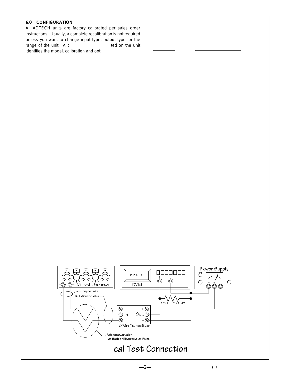
5.0 CONNECTIONS
Standard connections are shown below and on the
instrument face plate, Data Bulletin or on attached
supplementary sheets.
2
(2/ 0) 190-A-000098 Rev. A
6.0 CONFIGURATION
All ADTECH units are factory calibrated per sales order
instructions. Usually, a complete recalibration is not required
unless you want to change input type, output type, or the
range of the unit. A calibration sticker located on the unit
identifies the model, calibration and options present.
NOTE: For recalibration to the existing range proceed to
section 6.1; for new input or output range proceedas follows.
A. Remove power from the unit. Remove the right cover to
expose the 8 position switch and Jumper J1 on the input
PCB (just above the potentiometers).
B. Set output configuration jumpers per table 1 in section
8.0.
C. Set switch 3 position 1 forupscale or downscaleburnout.
Setswitch3position2toLinearizedornon-linearizedper
table 2, section 8.0. Re-apply power to the unit.
D. Set switch 3 position 3 to the on position and adjust the
output ZERO potentiometer for the proper output.
E. Set switch 3 position 3 to off and position 4 to on. Adjust
the output SPAN potentiometer for full scale output.
Repeat steps D and E until you reach the desired
accuracy. (Note: you can check the midscale value by
depressing switch 3 positions 3 and 4 simultaneously.)
F. Return switch 3 positions 3 and 4 to the off position, and
proceed with section 6.1 below to finish the calibration.
6.1 CALIBRATION
A. Apply the zero input value at the input terminals of the
unit. Depress and hold the ZERO input calibration push
button switch until the ZERO status led flashes. You
have just set the input zero, and the output should be at
your zero value after a short time delay.
B. Apply the full scale input value at the input terminals.
Depressandholdthe SPAN inputcalibration pushbutton
switch until the SPAN status led flashes. You have just
set the full scale value and the output should be at full
scale after a short delay.
C. Calibration is complete. Check the calibration with
various input values and verify the output values.
7.0 FIELD TROUBLE SHOOTING GUIDE
This sectionoffers a simple, first level trouble-shooting aid for
an apparent instrument malfunction.
SYMPTOM CORRECTIVE ACTION
No Output 1. Check the input and output
connections carefully.
2. Check that the power supply
polarity is correct and that the
output loop power is present on
the indicated terminals.
3. Check that the input source(s) is
correct and that it changes
magnitude between zero and full
scale values when so adjusted.
4. Make sure the output loop is
complete and that the correct
meter range is selected.
All external checks are complete.
Problem seems to be internal.
The instrument is made of small components.
Troubleshooting beyond the above may be difficult with out
special equipment. We do not recommend attempting repair
of the unit in the field. ADTECH offers a very responsive
repair policy. Contact theADTECH factory for information on
repair and return at 716-383-8280 or 716-383-8386(FAX).

3
(2/ 0) 190-A-000098 Rev. A
Input PCB Output PCB
TC Type 5 6 7 8
B Off Off Off Off
C On Off Off Off
D Off On Off Off
E On On Off Off
G Off Off On Off
J On Off On Off
K Off On On Off
N OnOnOnOff
R Off Off Off On
S On Off Off On
T Off On Off On
Table 3
8.0 TABLES
Output Configuration Jumpers
Output
Output PCB
(Small Board) Input PCB
(Large Board)
J1 J2 J1
4-20mA A A B
0-20mA A A A
0-10mA A B A
0-1mA A C A
1-5V B A B
0-5V B A A
0-10V C A A
Table 1
Configuration Switch SW3
Switch
Position Function
1Off Downscale burnout
On Upscale burnout
2Off No Linearization
On Linearized
3Off Normal Operation
On Output the zero Value
4Off Normal Operation
On Output the span Value
5,6,7,8 See Table 3
Table 2
Configuration Switch SW3 - TC Type T/C Range and Error
Table 4
!
"# $%&
'
8.1 PCB LAYOUT

4
(2/ 0) 190-A-000098 Rev. A
R
(
ohm
)
(
V
supply
5
)
1000
I
ou
t
max.
mA
9.0 SPECIFICATIONS
INPUT/OUTPUT
INPUT SIGNAL
a. Standard NIST Thermocouple (see Table 3) (Z in
greater than 22 megohm).
b. Conversion to 0.3
V input resolution linearized to 0.1
C conformance - (rms measured noise at 20 Hz
conversion rate is 5
V maximum). Conversion is
filtered to 5.24 Hz bandwidth.
OUTPUT SIGNALS
4-20 mA DC, 0-20 mA DC, 0-10 mA DC, 0-1 mA DC,
0-5 V DC, 1-5 V DC, 0-10 V DC
OUTPUT LOOP DRIVE CAPABILITY
I out 0-20 mA or 4-20 mA (22 mA maximum)
V
supply 15 24 36 42
R (ohm) 500 950 1550 1850
PERFORMANCE
a. Calibrated Accuracy: ± 0.1% of mv input
b. Independent Linearity: ± 0.05% maximum; ± 0.02%
typical
c. Repeatability: ± 0.01% maximum; ± 0.004% typical
d. Zero TC: ±0.15
V /
C
e. Span TC: ± 30 ppm of span max/
C
f. Load Effect: ± 0.005% zero to full load
g. Output Ripple: 10 mV (p-p) maximum
h. Response Time: 67 milliseconds (10 to 90% step
response)
i. Bandwidth (-3 db): 5.24 Hz
j. Temperature Range: -25
to 185
F (-31
to 85
C)
operating; -40
to 200
F (-40
to 93
C) storage
k. Power Supply Effect: ± 0.005% over operating range
l. Isolation: Input/output/case: 600 VAC, 1000 VDC
m. Cold Junction Sensor Error: 0.5
Cmax (-31
to
85
C)
n. Burnout current: 0.1
a - nominal
Note: All accuracies are given as a percentage of span
POWER
a. 15 to 42 VDC - standard, 28 mA typical, 33 mA max
MECHANICAL
a. Electrical Classification: general purpose
b. Connection: Screw, compression type, accepts up to
14 AWG
c. Controls: 8 position switch, input ZERO and SPAN
push button switch and status led’s, output SPAN and
ZERO pots
d. Mounting: DIN Surface, Snap-Track, or NEMA 4,7
e. Weight: Net Unit: 4 oz (115 grams)
Shipping: 7 oz (200 grams)
OPTIONS
Option
Number Description
H 15D Explosion proof: Class 1, Group B, C &
D
H 23 Two (2) inch pipe mounting plate and
clamps
H 25 Snap track mounting ( specify)
H 26 Surface mounting (specify)
H 27 NEMA 4 enclosure (up to 3 units)
H 29 T 35 DIN "T" rail two (2) feet long
H 30 T 32 DIN "G" rail two (2) feet long
10.0 OUTLINE MOUNTING
Other Adtech Transmitter manuals


Popular Transmitter manuals by other brands


Beyerdynamic
Beyerdynamic Unite TH quick start guide

BBC Bircher
BBC Bircher XRF-TI Original operating instructions

Continental Automotive
Continental Automotive 5WK50079 user manual

Emerson
Emerson Rosemount 3051G quick start guide

NBB
NBB Nano-L SMJ operating instructions

Hyundai
Hyundai FMT 419 BTCHARGE instruction manual

dji
dji Transmission High-Bright Monitor Combo manual

Vaisala
Vaisala TMI110 quick guide

Endress+Hauser
Endress+Hauser iTEMP TMT187 operating instructions

CYP
CYP CH-1103TX Operation manual

Absolute Process Instruments
Absolute Process Instruments AP11400 G quick start guide
blukii
blukii Smart Beacon Wear 1000 manual