Vega VEGABAR 86 User manual

Quick setup guide
Pressure transmitter with ceramic
measuring cell
VEGABAR 86
Secondary sensor for electronic dierential
pressure
Document ID: 46334

2
Contents
VEGABAR 86 • Secondary sensor for electronic dierential pressure
46334-EN-220624
Contents
1 About this document ............................................................................................................... 3
1.1 Function ........................................................................................................................... 3
1.2 Target group..................................................................................................................... 3
1.3 Symbols used................................................................................................................... 3
2 For your safety ......................................................................................................................... 4
2.1 Authorised personnel ....................................................................................................... 4
2.2 Appropriate use................................................................................................................ 4
2.3 Warning about incorrect use............................................................................................. 4
2.4 General safety instructions............................................................................................... 4
2.5 EU conformity................................................................................................................... 4
2.6 Environmental instructions ............................................................................................... 5
3 Product description ................................................................................................................. 6
3.1 Conguration.................................................................................................................... 6
4 Mounting................................................................................................................................... 7
4.1 General instructions for use of the instrument .................................................................. 7
4.2 Ventilation and pressure compensation............................................................................ 7
4.3 Combination Primary/Secondary sensor.......................................................................... 7
5 Connecting to power supply................................................................................................. 10
5.1 Connecting..................................................................................................................... 10
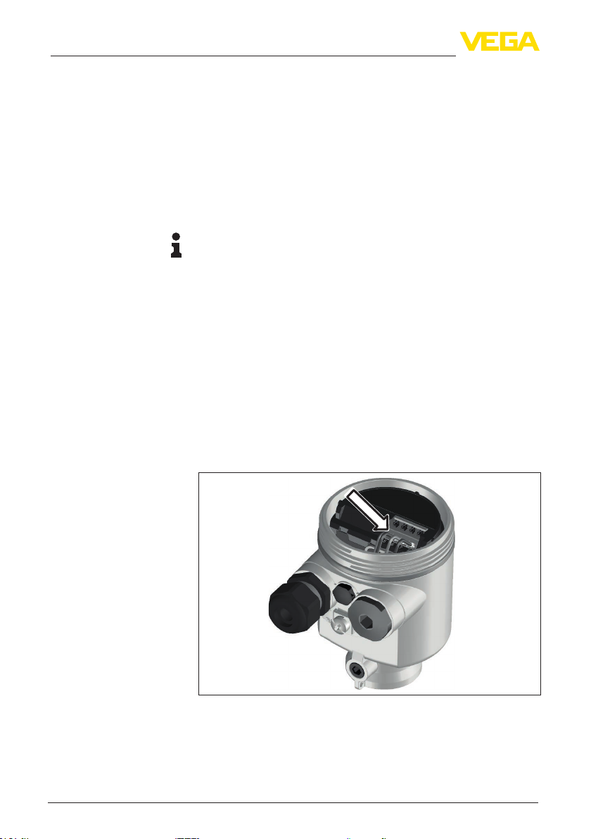
5.2 Single chamber housing................................................................................................. 11
5.3 Connection example ...................................................................................................... 11
6 Set up with the display and adjustment module ................................................................ 13
6.1 Parameter adjustment - Quick setup .............................................................................. 13
6.2 Parameter adjustment - Extended adjustment................................................................ 17
6.3 Menu overview ............................................................................................................... 18
7 Supplement ............................................................................................................................ 21
7.1 Technical data ................................................................................................................ 21
Information:
This quick setup guide enables quick setup and commissioning of
your instrument.
You can nd supplementary information in the corresponding, more
detailed Operating Instructions Manual as well as the Safety Manual
that comes with instruments with SIL qualication. These manuals are
available on our homepage.
Operating instructions VEGABAR 86 - Secondary sensor for
electronic dierential pressure: Document-ID 45052
Editing status of the quick setup guide: 2022-04-20

3
1 About this document
VEGABAR 86 • Secondary sensor for electronic dierential pressure
46334-EN-220624
1 About this document
1.1 Function
This instruction provides all the information you need for mounting,
connection and setup as well as important instructions for mainte-
nance, fault rectication, the exchange of parts and the safety of the
user. Please read this information before putting the instrument into
operation and keep this manual accessible in the immediate vicinity
of the device.
1.2 Target group
This operating instructions manual is directed to trained personnel.
The contents of this manual must be made available to the qualied
personnel and implemented.
1.3 Symbols used
Document ID
This symbol on the front page of this instruction refers to the Docu-
ment ID. By entering the Document ID on www.vega.com you will
reach the document download.
Information, note, tip: This symbol indicates helpful additional infor-
mation and tips for successful work.
Note: This symbol indicates notes to prevent failures, malfunctions,
damage to devices or plants.
Caution: Non-observance of the information marked with this symbol
may result in personal injury.
Warning: Non-observance of the information marked with this symbol
may result in serious or fatal personal injury.
Danger: Non-observance of the information marked with this symbol
results in serious or fatal personal injury.
Ex applications
This symbol indicates special instructions for Ex applications.
• List
The dot set in front indicates a list with no implied sequence.
1 Sequence of actions
Numbers set in front indicate successive steps in a procedure.
Disposal
This symbol indicates special instructions for disposal.

4
2 For your safety
VEGABAR 86 • Secondary sensor for electronic dierential pressure
46334-EN-220624
2 For your safety
2.1 Authorised personnel
All operations described in this documentation must be carried out
only by trained, qualied personnel authorised by the plant operator.
During work on and with the device, the required personal protective
equipment must always be worn.
2.2 Appropriate use
As Secondary Device, the VEGABAR 86 is part of an electronic dif-
ferential pressure meaasurement.
You can nd detailed information about the area of application in
chapter " Product description".
Operational reliability is ensured only if the instrument is properly
used according to the specications in the operating instructions
manual as well as possible supplementary instructions.
2.3 Warning about incorrect use
Inappropriate or incorrect use of this product can give rise to applica-
tion-specic hazards, e.g. vessel overll through incorrect mounting
or adjustment. Damage to property and persons or environmental
contamination can result. Also, the protective characteristics of the
instrument can be impaired.
2.4 General safety instructions
This is a state-of-the-art instrument complying with all prevailing
regulations and directives. The instrument must only be operated in a
technically awless and reliable condition. The operator is responsi-
ble for the trouble-free operation of the instrument. When measuring
aggressive or corrosive media that can cause a dangerous situation
if the instrument malfunctions, the operator has to implement suitable
measures to make sure the instrument is functioning properly.
The safety instructions in this operating instructions manual, the na-
tional installation standards as well as the valid safety regulations and
accident prevention rules must be observed by the user.
For safety and warranty reasons, any invasive work on the device
beyond that described in the operating instructions manual may be
carried out only by personnel authorised by the manufacturer. Arbi-
trary conversions or modications are explicitly forbidden. For safety
reasons, only the accessory specied by the manufacturer must be
used.
To avoid any danger, the safety approval markings and safety tips on
the device must also be observed.
2.5 EU conformity
The device fulls the legal requirements of the applicable EU direc-
tives. By axing the CE marking, we conrm the conformity of the
instrument with these directives.

5
2 For your safety
VEGABAR 86 • Secondary sensor for electronic dierential pressure
46334-EN-220624
The EU conformity declaration can be found on our homepage.
2.6 Environmental instructions
Protection of the environment is one of our most important duties.
That is why we have introduced an environment management system
with the goal of continuously improving company environmental pro-
tection. The environment management system is certied according
to DIN EN ISO 14001.
Please help us full this obligation by observing the environmental
instructions in this manual:
• Chapter " Packaging, transport and storage"
• Chapter " Disposal"

6
3 Product description
VEGABAR 86 • Secondary sensor for electronic dierential pressure
46334-EN-220624
3 Product description
3.1 Conguration
The type label contains the most important data for identication and
use of the instrument:
7
6
4
5
2
3
1
Conne
Conne
Conn
C
Conn
C
CC
prim
prim
prim
prim
p
ary dary d
ary d
ar
ary d
d
evice
evice
i
vice
vic
evice
Connect to
p
rimar
y
Fig. 1: Layout of the type label (example)
1 Product code
2 Field for approvals
3 Technical data
4 Serial number of the instrument
5 QR code
6 Symbol of the device protection class
7 ID numbers, instrument documentation
The type label contains the serial number of the instrument. With it
you can nd the following instrument data on our homepage:
• Product code (HTML)
• Delivery date (HTML)
• Order-specic instrument features (HTML)
• Operating instructions and quick setup guide at the time of ship-
ment (PDF)
• Test certicate (PDF) - optional
Move to " www.vega.com" and enter in the search eld the serial
number of your instrument.
Alternatively, you can access the data via your smartphone:
• Download the VEGA Tools app from the " Apple App Store" or the
" Google Play Store"
• Scan the QR-code on the type label of the device or
• Enter the serial number manually in the app
Type label
Serial number - Instru-
ment search

7
4 Mounting
VEGABAR 86 • Secondary sensor for electronic dierential pressure
46334-EN-220624
4 Mounting
4.1 General instructions for use of the instrument
Protect your instrument against moisture ingress through the following
measures:
• Use a suitable connection cable (see chapter " Connecting to
power supply")
• Tighten the cable gland or plug connector
• Lead the connection cable downward in front of the cable entry or
plug connector
This applies mainly to outdoor installations, in areas where high
humidity is expected (e.g. through cleaning processes) and on cooled
or heated vessels.
Note:
Make sure that during installation or maintenance no moisture or dirt
can get inside the instrument.
To maintain the housing protection, make sure that the housing lid is
closed during operation and locked, if necessary.
4.2 Ventilation and pressure compensation
1 2 3
4 4 4
Fig. 2: Position of the lter element - non-Ex, Ex-ia version
1 Plastic, stainless steel housing (precision casting)
2 Aluminium housing
3 Stainless steel housing (electropolished)
4 Filter element
With the following instruments a blind plug is installed instead of the
lter element:
• Instruments in protection IP66/IP68 (1 bar) - ventilation via capillar-
ies in non-detachable cable
• Instruments with absolute pressure
4.3 Combination Primary/Secondary sensor
In principle, any sensor combination within the instrument series is
allowed. The following requirements must be fullled:
• Conguration of the sensor suitable for electronic dierential pres-
sure
• Pressure type is identical for both sensors, i.e. relative pressure/
relative pressure or absolute pressure/absolute pressure
Protection against mois-
ture
Filter element - Position

8
4 Mounting
VEGABAR 86 • Secondary sensor for electronic dierential pressure
46334-EN-220624
• Primary Device measures the higher pressure
• Measurement setup as shown in the following chapters
The measuring range of each sensor is selected such that it ts the
measuring loop. For this, the max. recommended turn down must be
noted. See chapter " Technical data". It is absolutely necessary the
the measuring ranges of Primary and Secondary Device correspond.
Measurement result = Measured value of Primary (total pres-
sure) - measured value of Secondary (static pressure)
Depending on the application, individual combinations can result, see
following examples:
Data
Application: Level measurement
Medium: Water
Vessel height: 12 m, hydrostatic pressure = 12 m x 1000 kg/m3x
9.81 m/s2 = 117.7 kPa = 1.18 bar
Superimposed pressure: 1 bar
Total pressure: 1.18 bar + 1 bar = 2.18 bar
Instrument selection
Nominal measuring range Primary: 2.5 bar
Nominal measuring range Secondary: 1 bar
Turn Down: 2.5 bar/1.18 bar = 2.1 : 1
Data
Application: Level measurement
Medium: Water
Vessel height: 500 mm, hydrostatic pressure = 0.50 m x 1000 kg/m3x
9.81 m/s2 = 4.9 kPa = 0.049 bar
Superimposed pressure: 350 mbar = 0.35 bar
Total pressure: 0.049 bar + 0.35 bar = 0.399 bar
Instrument selection
Nominal measuring range Primary: 0.4 bar
Nominal measuring range Secondary: 0.4 bar
Turn Down: 0.4 bar /0.049 bar = 8.2 : 1
Data
Application: Dierential pressure measurement
Medium: Gas
Static pressure: 0.8 bar
Dierential pressure on orice: 50 mbar = 0.050 bar
Total pressure: 0.8 bar + 0.05 bar = 0.85 bar
Instrument selection
Nominal measuring range Primary: 1 bar
Nominal measuring range Secondary: 1 bar
Turn Down: 1 bar/0.050 bar = 20 : 1
Example - large vessel
Example - small vessel
Example - orice in
pipeline

9
4 Mounting
VEGABAR 86 • Secondary sensor for electronic dierential pressure
46334-EN-220624
The measuring result (level, pressure dierence) as well as measured
value Secondary (static or superimposed pressure) are output by the
sensor. Depending on the instrument version, output as 4 … 20 mA
signal or digitally via HART, Probus PA or Foundation Fieldbus.
Output measured values

10
5 Connecting to power supply
VEGABAR 86 • Secondary sensor for electronic dierential pressure
46334-EN-220624
5 Connecting to power supply
5.1 Connecting
The connection to the Primary Device is carried out through spring-
loaded terminals in the respective housing. For this, use the supplied,
confectioned cable. Solid cores as well as exible cores with cable
end sleeves are inserted directly into the terminal openings.
In case of exible cores without end sleeves, press the terminal from
above with a small screwdriver, the terminal opening is then free.
When the screwdriver is released, the terminal closes again.
Information:
The terminal block is pluggable and can be removed from the
electronics. To do this, lift the terminal block with a small screwdriver
and pull it out. When reinserting the terminal block, you should hear it
snap in.
You can nd further information on the max. wire cross-section under
" Technical data - Electromechanical data".
Proceed as follows:
1. Unscrew the housing lid
2. Loosen compression nut of the cable gland and remove blind
plug
3. Remove approx. 10 cm (4 in) of the cable mantle, strip approx.
1 cm (0.4 in) insulation from the individual wires or use supplied
connection cable
4. Insert the cable into the sensor through the cable entry
Fig. 3: Connection steps 5 and 6
5. Insert the wire ends into the terminals according to the wiring plan
6. Check the hold of the wires in the terminals by lightly pulling on
them
Connection technology
Connection procedure

11
5 Connecting to power supply
VEGABAR 86 • Secondary sensor for electronic dierential pressure
46334-EN-220624
7. Connect the shielding to the internal ground terminal, connect the
external ground terminal to potential equalisation
8. Tighten the compression nut of the cable entry gland. The seal
ring must completely encircle the cable
9. Unscrew the blind plug on the Primary, screw in the supplied
cable gland
10. Connection cable to Primary, see steps 3 to 8
11. Screw the housing lid back on
The electrical connection is nished.
5.2 Single chamber housing
The following illustration applies to the non-Ex, Ex-ia and Ex-d-ia
version.
5678 4
2
1
connect to Primary
Fig. 4: Wiring plan VEGABAR 86 Secondary Device
1 To the Primary Device
2 Ground terminal for connection of the cable screening 1)
5.3 Connection example
5678
4
2
3
1
4
connect to Primary
5
12
+
( ) (-)
678
4...20mA
Fig. 5: Connection example, electronic dierential pressure
1 Primary Device
2 Secondary Device
3 Connection cable
4 Supply and signal circuit Primary Device
Electronics and connec-
tion compartment
Connection example,
electronic dierential
pressure
1) Connect shielding here. Connect ground terminal on the outside of the hous-
ing to ground as prescribed. The two terminals are galvanically connected.

12
5 Connecting to power supply
VEGABAR 86 • Secondary sensor for electronic dierential pressure
46334-EN-220624
The connection between Primary and Secondary Device is carried
out acc. to the table:
Primary Device Secondary Device
Terminal 5 Terminal 5
Terminal 6 Terminal 6
Terminal 7 Terminal 7
Terminal 8 Terminal 8

13
6 Set up with the display and adjustment module
VEGABAR 86 • Secondary sensor for electronic dierential pressure
46334-EN-220624
6 Set up with the display and adjustment
module
6.1 Parameter adjustment - Quick setup
To quickly and easily adapt the sensor to the application, select the
menu item " Quick setup" in the start graphic on the display and
adjustment module.
Carry out the following steps in the sequence specied below. The
presettings apply to all applications.
You can nd " Extended adjustment" in the next sub-chapter.
Measurement loop name
In the rst menu item you assign a suitable measurement loop name.
Permitted are names with max. 19 characters.
Application
In this menu item you activate/deactivate the Secondary sensor for
electronic dierential pressure and select the application.
Note:
It is absolutely necessary to activate the Secondary sensor in ad-
vance to have the applications displayed in the electronic dierential
pressure measurement menus.
Units
In this menu item you determine the adjustment and temperature
units of the instrument. Depending on the selected application in the
menu item " Application", dierent adjustment units are available.
Unit, static pressure
In this menu item, you determine the unit of the static, i.e. superim-
posed pressure.
Position correction
In this menu item you compensate the inuence of the installation
position of the instrument (oset) on the measured value.
Min. adjustment
In this menu item you carry out the min. adjustment for level.
Enter the percentage value and the corresponding pressure value for
the min. level.
Max. adjustment
In this menu item you carry out the max. adjustment for level.
Presettings
Quick setup - Level meas-
urement

14
6 Set up with the display and adjustment module
VEGABAR 86 • Secondary sensor for electronic dierential pressure
46334-EN-220624
Enter the percentage value and the corresponding pressure value for
the max. level.
The quick setup for level measurement is nished.
Position correction
In this menu item you compensate the inuence of the installation
position of the instrument (oset) on the measured value.
Min. adjustment
In this menu item you carry out the min. adjustment for ow.
Enter the percentage value and the corresponding pressure value for
the min. ow.
Max. adjustment
In this menu item you carry out the max. adjustment for ow.
Enter the percentage value and the corresponding pressure value for
the max. ow.
Linearisation
In this menu item, you select the characteristics of the output signal.
The quick setup for ow measurement is nished.
Unit, static pressure
In this menu item, you determine the unit of the static, i.e. superim-
posed pressure.
Position correction
In this menu item you compensate the inuence of the installation
position of the instrument (oset) on the measured value.
Zero adjustment
In this menu item you carry out the Zero adjustment for the dierential
pressure.
Enter the corresponding pressure value for 0 %.
Span adjustment
In this menu item you carry out the Span adjustment for the dieren-
tial pressure
Enter the corresponding pressure value for 100 %.
Quick setup - Flow meas-
urement
Quick setup - Dierential
pressure measurement

15
6 Set up with the display and adjustment module
VEGABAR 86 • Secondary sensor for electronic dierential pressure
46334-EN-220624
The quick setup for dierential pressure measurement is nished.
Unit, static pressure
In this menu item, you determine the unit of the static, i.e. superim-
posed pressure.
Position correction
In this menu item you compensate the inuence of the installation
position of the instrument (oset) on the measured value.
Distance
In this menu item, you enter the installation distance between Primary
and Secondary sensor.
Min. adjustment
In this menu item you carry out the min. adjustment for density.
Enter the percentage value and the corresponding density value for
the min. density.
Max. adjustment
In this menu item you carry out the max. adjustment for density.
Enter the percentage value and the corresponding density value for
the max. density.
The quick setup for density measurement is nished.
Unit, static pressure
In this menu item, you determine the unit of the static, i.e. superim-
posed pressure.
Position correction
In this menu item you compensate the inuence of the installation
position of the instrument (oset) on the measured value.
Distance
In this menu item, you enter the installation distance between Primary
and Secondary sensor.
Min. adjustment
In this menu item, you carry out the adjustment for the min. height of
the interface.
Enter the percentage value and the corresponding height of the
interface.
Max. adjustment
In this menu item, you carry out the adjustment for the max. height of
the interface.
Enter the percentage value and the corresponding height of the
interface.
Quick setup - Density
measurement
Quick setup - Interface
measurement

16
6 Set up with the display and adjustment module
VEGABAR 86 • Secondary sensor for electronic dierential pressure
46334-EN-220624
The quick setup for interface measurement is nished.
Unit, static pressure
In this menu item, you determine the unit of the static, i.e. superim-
posed pressure.
Position correction
In this menu item you compensate the inuence of the installation
position of the instrument (oset) on the measured value.
Distance
In this menu item, you enter the installation distance between Primary
and Secondary sensor.
Min. adjustment
In this menu item you carry out the min. adjustment for level.
Enter the percentage value and the corresponding pressure value for
the min. level.
Max. adjustment
In this menu item you carry out the max. adjustment for level.
Enter the percentage value and the corresponding pressure value for
the max. level.
The quick setup for density-compensated level measurement is
hence nished.
VEGABAR 86 always measures pressure independently of the pro-
cess variable selected in the menu item " Application". To output the
selected process variable correctly, an allocation of the output signal
to 0 % and 100 % must be carried out (adjustment).
For the application " Interface", the hydrostatic pressure e.g. with
interface "Min." and interface "Max." is entered for the adjustment.
The position of the interface is detected by the Secondary sensor.
See following example:
Quick setup - density-
compensated level meas-
urement
Parameterization example

17
6 Set up with the display and adjustment module
VEGABAR 86 • Secondary sensor for electronic dierential pressure
46334-EN-220624
2
1
100%
0%
2 m
(78.74
")
h
0,8
1,0
Fig. 6: Parameter adjustment example "Min./max. adjustment, interface meas-
urement"
1 Min. interface = 0 % correspond to 0.0 mbar
2 Max. interface = 100 % correspond to 490.5 mbar
3 VEGABAR 86
4 VEGABAR 86 - Secondary sensor
If these values are not known, an adjustment with interface layers of
for example 10 % and 90 % is also possible. By means of these set-
tings, the layer of the actual interface is then calculated.
The real product level during the adjustment is not important, be-
cause the min./max. interface adjustment is always carried out without
changing the product level. These settings can be made ahead of
time without the instrument having to be installed.
6.2 Parameter adjustment - Extended adjustment
For technically demanding measuring points, you can carry out
extended settings in " Extended adjustment".
The main menu is divided into ve sections with the following func-
tions:
Setup: Settings, e.g., for measurement loop name, application, units,
position correction, adjustment, signal output
Main menu

18
6 Set up with the display and adjustment module
VEGABAR 86 • Secondary sensor for electronic dierential pressure
46334-EN-220624
Display: Settings, e.g., for language, measured value display, lighting
Diagnosis: Information, e.g. on instrument status, pointer, measure-
ment reliability, simulation
Additional adjustments: PIN, date/time, reset, copy function
Info: Instrument name, hardware and software version, date of manu-
facture, sensor features
In the main menu item " Setup", the individual submenu items should
be selected one after the other and provided with the correct param-
eter values.
The following submenu points are available:
In the following section, the menu items from the menu " Setup" for
electronic dierential pressure measurement are described in detail.
Depending on the selected application, dierent sections are relevant.
Information:
Further menu items of the menu " Setup" as well as the complete
menus " Display", " Diagnosis", " Additional adjustments" and " Info"
are described in the operating instructions of the respective Primary
Device.
6.3 Menu overview
The following tables show the adjustment menu of the instrument.
Depending on the instrument version or application, all menu items
may not be available or some may be dierently assigned.
Note:
You can nd further menu items in the operating instructions of the
respective Primary Device.
Setup
Menu item Parameter Default setting
Measurement
loop name
19 alphanumeric
characters/special
characters
Sensor
Application Application Level
Secondary Device
for electronic dif-
ferential pressure
Deactivated
Units Unit of measure-
ment
mbar (with nominal measuring range
≤ 400 mbar)
bar (with nominal measuring ranges
≥ 1 bar)
Static pressure bar

19
6 Set up with the display and adjustment module
VEGABAR 86 • Secondary sensor for electronic dierential pressure
46334-EN-220624
Menu item Parameter Default setting
Position correc-
tion
0.00 bar
Adjustment Distance (with
density and inter-
face)
1.00 m
Zero/Min. adjust-
ment
0.00 bar
0.00 %
Span/Max. adjust-
ment
Nominal measuring range in bar
100.00 %
Damping Integration time 0.0 s
Linearisation Linear, cylindrical
tank, … user-de-
ned
Linear
Current output Current output -
Mode
Output characteristics
4 … 20 mA
Reaction when malfunctions occur
≤ 3.6 mA
Current output -
Min./Max.
3.8 mA
20.5 mA
Lock adjustment Blocked, released Last setting
Menu item Default setting
Menu language Order-specic
Displayed value 1 Current output in %
Displayed value 2 Ceramic measuring cell: Measuring cell tempera-
ture in °C
Metallic measuring cell: Electronics temperature
in °C
Display format Number of positions after the decimal point, auto-
matically
Backlight Switched on
Menu item Parameter Default setting
Device status -
Peak value Pressure Current pressure measured value
Pointer function
temp.
Temperature Actual measuring cell and electronic
temperature
Display
Diagnostics

20
6 Set up with the display and adjustment module
VEGABAR 86 • Secondary sensor for electronic dierential pressure
46334-EN-220624
Menu item Parameter Default setting
Simulation Pressure, percent,
signal output,
linearized per-
cent, measuring
cell temperature,
electronics tem-
perature
-
Menu item Parameter Default setting
Date/Time Actual date/Actual time
Reset Delivery status, basic settings
Copy instru-
ment settings
Read from sensor, write in-
to sensor
Scaling Scaling size Volume in l
Scaling format 0 % corresponds to 0 l
100 % corresponds to 0 l
Current output Current output - Meas. vari-
able
Lin. percent - Level
Current output - Adjustment 0 … 100 % correspond to
4 … 20 mA
HART mode Address 0
DP ow ele-
ment
Unit m3/s
Adjustment 0.00 % correspond to 0.00 m3/
s
100.00 %, 1 m3/s
Special pa-
rameters
Service-Login No reset
Menu item Parameter
Device name VEGABAR 86
Instrument version Hardware and software version
Factory calibration date Date
Sensor characteristics Order-specic characteristics
Additional adjustments
Info
Other manuals for VEGABAR 86
14
Table of contents
Other Vega Transmitter manuals

Vega
Vega VEGABAR 83 User manual

Vega
Vega VEGABAR 86 User manual

Vega
Vega VEGAWELL 52 User manual

Vega
Vega VEGABAR 51 User manual

Vega
Vega RMT-10 User manual

Vega
Vega VEGABAR 83 User manual

Vega
Vega VEGABAR 86 User manual

Vega
Vega VEGABAR 86 User manual

Vega
Vega VEGABAR 80 Series Wiring diagram

Vega
Vega VEGABAR 14 User manual

Vega
Vega VEGABAR 66 User manual

Vega
Vega VEGAWELL 52 User manual

Vega
Vega VEGABAR 82 User manual

Vega
Vega VEGABAR 81 User manual

Vega
Vega VEGABAR 82 User manual

Vega
Vega VEGABAR 86 User manual

Vega
Vega VEGABAR 83 User manual

Vega
Vega VEGABAR 17 User manual

Vega
Vega VEGABAR 83 User manual

Vega
Vega VEGABAR 81 User manual