manuals.online logo
Brands
  1. Home
  2. •
  3. Brands
  4. •
  5. ADTRAN
  6. •
  7. Network Hardware
  8. •
  9. ADTRAN Dual Nx56/64 User manual

ADTRAN Dual Nx56/64 User manual

DESCRIPTION
The Total Access 1500 Dual Nx56/64 is a DSU data
port with two circuits that each deliver T1 data over
a V.35 interface. The unit is designed specifically for
the Total Access 1500 chassis. Each circuit of the
Dual Nx56/64 can be craft provisioned to provide
up to 24 channels in increments of N=56 or 64k, or
one channel. Design operation is to transmit or
receive high rate synchronous data from data
terminal equipment (DTE) over T1. Transmission
data rates for each circuit of the Dual Nx56/64
range from 56 kbps to 1.536 Mbps using noncon-
tiguous bandwidth assignment. The Dual Nx56/64
features:
♦Noncontiguous bandwidth assignment
♦Built-in DSU
♦Two circuits with synchronous operation to
1.536 Mbps in increments of 56/64 kbps
♦50% duty cycle output clock at all rates
♦Hot swappable
♦User provisioned via craft interface on SCU
FRONT PANEL LEDS
Provisioning Options
Label Status Description
STAT z
z
2
z
Green
Yellow
Yellow Flashing
Red
Dual Nx56/64 is operating normally
Dual Nx56/64 is in test mode
No DS0s have been assigned
Dual Nx56/64 failure ; T1 down ; No data transfer
RD zGreen Transmitting data from the customer to the
network (T1)
TD zGreen Receiving data from the network and transmitting
to the customer (V.35)
Option Description Default
Circuit Selects the active port Port 1
Channel
Rate
Selects channel data rate:
– 56 kbps
– 64 kbps
64 kbps
DSR Normal – DSR follows DTR
Forced ON – DSR forced on and DTR ignored
Normal
CTS Normal – CTS follows RTS
Forced ON – CTS forced on and RTS ignored
Normal
DCD Normal – DCD active when loops in sync and/or
T1 carrier present
Forced ON – Causes DCD to be forced on always
Normal
CLOCK Auto – Measures the delay between the DTE data
and its clock and automatically selects
between Internal and INT-INV
Internal – Allows the Nx56/64 to provide transmit
data clock
External – Derives DTE transmit clock from the DTE
device
Internal Invert – Inverted form of the DTE TX CLK setting
Auto
Total Access 1500
Dual Nx56/64 Data Service Unit Data Port
(DSU DP)
INSTALLATION
After unpacking the Dual Nx56/64, inspect it for damage.
If damage is noted, file a claim with the carrier and then
contact ADTRAN. For more information, refer to the
warranty.
To install the Dual Nx56/64, perform the following steps:
1. Insert Dual Nx56/64 into any two consecutive slots
of the Total Access 1500 chassis. To insert, hold the
Dual Nx56/64 by the faceplate while supporting the
bottom edge of the card. Align the card edge with the
guide grooves in the first of the two consecutive slots
chosen to install the card in. Insert into chassis until
the edge connector seats firmly into the chassis back-
plane. Lock the unit in place by pushing in on the
locking lever.
2. Check STAT LED for operational status.
3. Assess Provisioning. The factory default settings are
listed in the Provisioning Options table. If further
provisioning is desired proceed to step 4.
4. Connect VT100 compatible terminal to SCU faceplate
ADMIN port. Craft port settings are: 9600 baud, no
parity, 8 data bits, 1 stop bit, and no flow control.
a. Connect DB-9 cable
b. Run terminal emulation program
c. If using Windows HyperTerminal, open by
selecting Programs/Accessories/HyperTerminal
d. Login and navigate through ADMIN port menu
structure
NOTE: To ensure proper display background, select VT100
Terminal Emulation under settings.
5. Navigate through menus to perform desired function.
NOTE: To traverse through the menus, select the desired
entry and press Enter. To work backwards in the
menu, press ESC (escape key.)
6. Allocate channels to the Dual Nx56/64.
a. Connect VT100 compatible terminal to SCU.
b. Select the online LIU.
c. Set the bank mode to manual map.
d. Select the time slot assignment option.
e. Select the T1 to assign time slots from.
f. Select the time slot to assign to a port of the
Dual Nx56/64.
g. Enter the slot that contains the Dual Nx56/64
(i.e. if the card takes up slots 23 and 24 of the
bank, enter slot 23.)
h. Select the appropriate port of the Dual Nx56/64
to assign the time slot to.
i. Select option 3 to assign the DS0.
j. Select “Yes” to confirm the assignment or “No”
to cancel assignment.
CLEI: VAL4NS0D_ _
Product P/N: 1180025L1
Issue Date: 0803
Document P/N: 61180025L1-22B
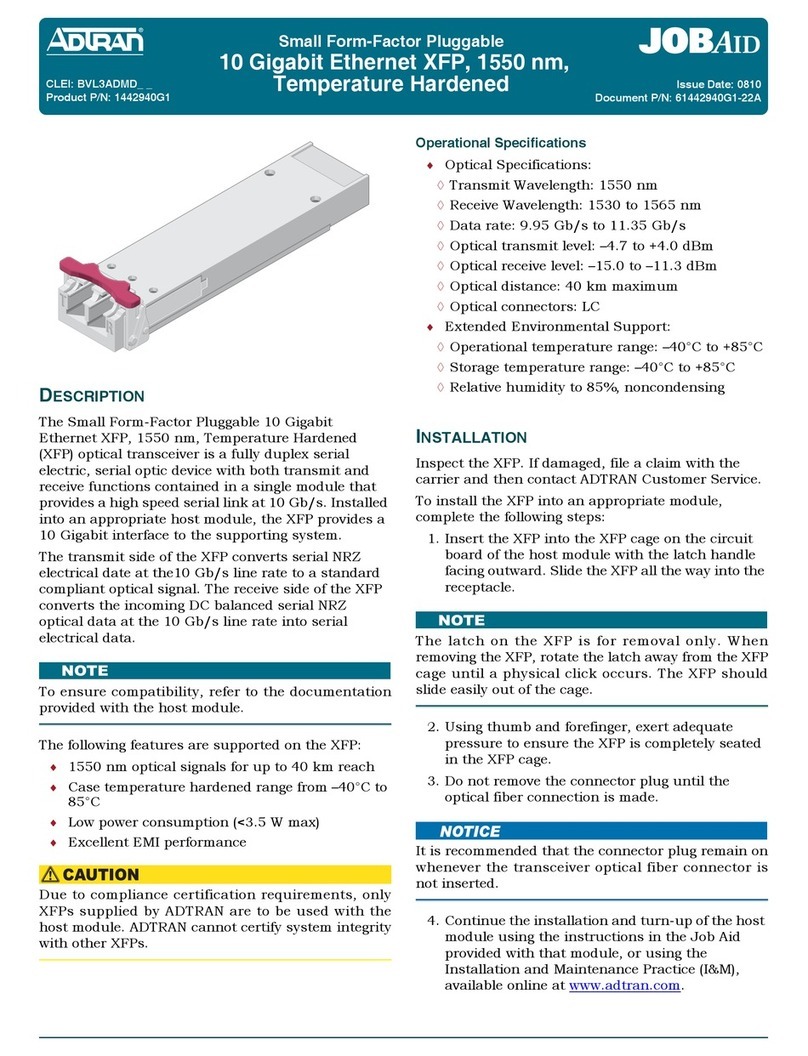
Total Access 1500
Dual Nx56/64 Data Service Unit Data Port
(DSU DP)
CONNECTIONS
All connections are made through the double stacked DB-26
connectors on the faceplate of the Dual Nx56/64. A DB-26 to V.35
cable (P/N 1200167L1) is available to provide a V.35 interface.
Wiring Connections
COMPLIANCE
The Dual Nx56/64 is intended to be installed in a Restricted Access
Location.
This device complies with Part 15 of the FCC rules. Operation is
subject to the following two conditions: (1) This device may not
cause harmful interference, and (2) this device must accept any
interference received, including interference that may cause
undesired operation.
Changes or modifications not expressly approved by ADTRAN could
void the user’s authority to operate this equipment.
DB-26 V.35
Name Pin Pin Name
Frm Gnd 1 A Frm Gnd
RTS 4 C RTS
CTS 5 D CTS
DSR 6 E DSR
Sig GND 7, 21 BSig GND
CD 8 F CD
TxD A 9 P TxD A
TxD B 10 STxD B
RxD A 11 RRxD A
RxD B 12 TRxD B
Ext TxC A 13 UExt TxC A
RI 17 JRI
LL 18 LLL
TM 19 NN TM
DTR 20 HDTR
TxC A 22 YTxC A
TxC B 23 AA TxC B
RxC A 24 VRxC A
RxC B 25 XRxC B
Ext TxC B 26 WExt TxC B
Configuration Code Input Output
Power Code (PC) C C
Telecommunication Code (TC) – –
Installation Code (IC) A –
7. Allocate a range of channels to the Dual Nx56/64.
a. Perform steps 6a through 6e.
b. Select the first time slot in the range of time slots that is
to be assigned to a port of the Dual Nx56/64.
c. Perform steps 6g and 6h.
d. Select option 4 to assign a range of DS0s.
e. Enter the range (the range should be entered starting
with the first DS0, then entering a dash or slash, and
finally entering the last DS0.)
8. Remove a channel from the Dual Nx56/64.
a. Select the T1 to remove time slots from, at the time slot
assignment screen.
b. Select the time slot you want to remove.
c. Select option 3 to remove time slot.
NOTE: To remove multiple time slots change the bank mode to single
T1. The LIU will remove all assigned time slots in use and
assign all cards in shelf the appropriate time slots depending
on their position in the shelf.
TESTING
To access the test menu, select the access module menu, then
select the slot containing the Dual Nx56/64 to test, and finally
select the test option.
NOTE: The loopbacks are used in conjunction with bit error rate test
(BERT) equipment.
DTE Loopback
♦The test loops back the entire data stream from the Dual Nx56/64
to the DTE.
♦Provides complete diagnostic picture of the V.35 interface path.
Network Loopback
♦Data is looped back across the T1.
♦Test can be initiated through the menu interface of the system
controller, or the Dual Nx56/64 can initiate a network loopback
from a remote unit using a V.54 test pattern.
511 Test Pattern
♦Forces the Dual Nx56/64 to send a 511 data pattern across the T1
over all channels to help with debugging.
MAINTENANCE
The Dual Nx56/64 does not require routine hardware maintenance
for normal operation. ADTRAN does not recommend that repairs be
attempted in the field. Repair services may be obtained by
returning the defective unit to ADTRAN. Refer to the warranty for
further information. Field support for software is provided through
upgrade facilities.
For more information, refer to the Installation and Maintenance Practice (P/N 61180025L1-5) available
online at www.adtran.com.
Warranty:ADTRAN will replace or repair this product within the warranty period if it does not meet its
published specifications or fails while in service. Warranty information can be found online
at www.adtran.com/warranty.
©2008 ADTRAN, Inc. All Rights Reserved.
PRICING AND AVAILABILITY 800.827.0807
TECHNICAL SUPPORT 800.726.8663
RETURN FOR REPAIR 256.963.8722
*61180025L1-22B*
C A U T I O N !
SUBJECT TO ELECTROSTATIC DAMAGE
OR DECREASE IN RELIABILITY.
HANDLING PRECAUTIONS REQUIRED.
CLEI: VAL4NS0D_ _
Product P/N: 1180025L1
Issue Date: 0803
Document P/N: 61180025L1-22B
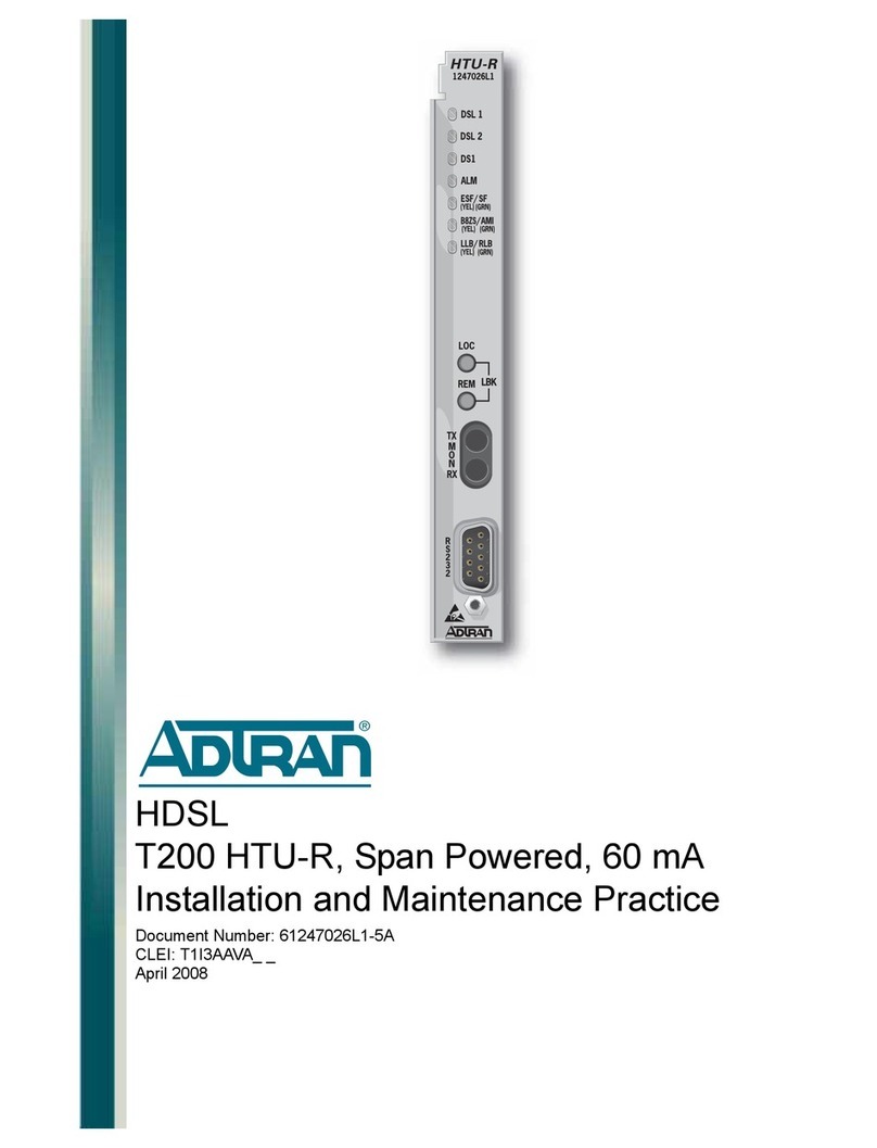
Other ADTRAN Network Hardware manuals

ADTRAN XFP NG-PON2 ONU User manual

ADTRAN

ADTRAN XFP NG-PON2 ONU User manual

ADTRAN NETVANTA 6355 User manual

ADTRAN

ADTRAN NETVANTA 6355 User manual

ADTRAN TRACER 5045 User guide

ADTRAN

ADTRAN TRACER 5045 User guide

ADTRAN MX2800 STS-1 User guide

ADTRAN

ADTRAN MX2800 STS-1 User guide

ADTRAN SLC-5 U-BR1TE III Instruction Manual

ADTRAN

ADTRAN SLC-5 U-BR1TE III Instruction Manual

ADTRAN Total Access 300 Instruction Manual

ADTRAN

ADTRAN Total Access 300 Instruction Manual

ADTRAN SHDSL NxNTU Instruction Manual

ADTRAN

ADTRAN SHDSL NxNTU Instruction Manual

ADTRAN ISU 512 User manual

ADTRAN

ADTRAN ISU 512 User manual

ADTRAN Total Access 372E User manual

ADTRAN

ADTRAN Total Access 372E User manual

ADTRAN 1202295L1 User manual

ADTRAN

ADTRAN 1202295L1 User manual

ADTRAN Total Access 300 Series User manual

ADTRAN

ADTRAN Total Access 300 Series User manual

ADTRAN TSU ACE Service manual

ADTRAN

ADTRAN TSU ACE Service manual

ADTRAN Smart 16e Shelf User manual

ADTRAN

ADTRAN Smart 16e Shelf User manual

ADTRAN DSU IV ESP User manual

ADTRAN

ADTRAN DSU IV ESP User manual

ADTRAN IQ 710 User guide

ADTRAN

ADTRAN IQ 710 User guide

ADTRAN U-BR1TE User manual

ADTRAN

ADTRAN U-BR1TE User manual

ADTRAN NetVanta 2300 User manual

ADTRAN

ADTRAN NetVanta 2300 User manual

ADTRAN ISU 512E User manual

ADTRAN

ADTRAN ISU 512E User manual

ADTRAN Octal IDSL DSLAM Octal IDSL User manual

ADTRAN

ADTRAN Octal IDSL DSLAM Octal IDSL User manual

ADTRAN SHDSL T1 Instruction Manual

ADTRAN

ADTRAN SHDSL T1 Instruction Manual

ADTRAN Total Access 1100F User manual

ADTRAN

ADTRAN Total Access 1100F User manual

ADTRAN NetVanta NetVanta ADSL NIM User manual

ADTRAN

ADTRAN NetVanta NetVanta ADSL NIM User manual

ADTRAN QFO-C Instruction Manual

ADTRAN

ADTRAN QFO-C Instruction Manual

ADTRAN NETVANTA OCTAL POE User manual

ADTRAN

ADTRAN NETVANTA OCTAL POE User manual

Popular Network Hardware manuals by other brands

RuggedCom RUGGED VDSL RS910L installation guide

RuggedCom

RuggedCom RUGGED VDSL RS910L installation guide

Patton electronics OnSite 2884 Getting started guide

Patton electronics

Patton electronics OnSite 2884 Getting started guide

RFID HF-3600E-RS232 product manual

RFID

RFID HF-3600E-RS232 product manual

Nortel 2340 Configuration guide

Nortel

Nortel 2340 Configuration guide

Raisecom Gazelle S1512i-4GF-8GE-PWR user manual

Raisecom

Raisecom Gazelle S1512i-4GF-8GE-PWR user manual

Aetina DeviceEdge AGX Orin Series user manual

Aetina

Aetina DeviceEdge AGX Orin Series user manual

ADPRO iFT Series Hardware installation manual

ADPRO

ADPRO iFT Series Hardware installation manual

EverFocus VANGUARD II 4x2H Quick installation guide

EverFocus

EverFocus VANGUARD II 4x2H Quick installation guide

Billion BiPAC 2071 White paper

Billion

Billion BiPAC 2071 White paper

Wisenet XRN-2010 Quick manual

Wisenet

Wisenet XRN-2010 Quick manual

Ericsson MINI-LINK 6351 Technical description

Ericsson

Ericsson MINI-LINK 6351 Technical description

Compatible Systems 8 Port 10 RIOP installation guide

Compatible Systems

Compatible Systems 8 Port 10 RIOP installation guide

Paradyne Jetstream CPX-1000 installation guide

Paradyne

Paradyne Jetstream CPX-1000 installation guide

JVC Milestone VR-N1600 Brochure & specs

JVC

JVC Milestone VR-N1600 Brochure & specs

ATC ODB-48/OSB installation manual

ATC

ATC ODB-48/OSB installation manual

Amperes iPX Series instruction manual

Amperes

Amperes iPX Series instruction manual

GMI Tricon instruction manual

GMI

GMI Tricon instruction manual

WIN Enterprises PL-80720 user manual

WIN Enterprises

WIN Enterprises PL-80720 user manual

manuals.online logo
manuals.online logoBrands
  • About & Mission
  • Contact us
  • Privacy Policy
  • Terms and Conditions

Copyright 2025 Manuals.Online. All Rights Reserved.