manuals.online logo
Brands
  1. Home
  2. •
  3. Brands
  4. •
  5. ADTRAN
  6. •
  7. Network Hardware
  8. •
  9. ADTRAN Total Access 351 User manual

ADTRAN Total Access 351 User manual

1
jobAid
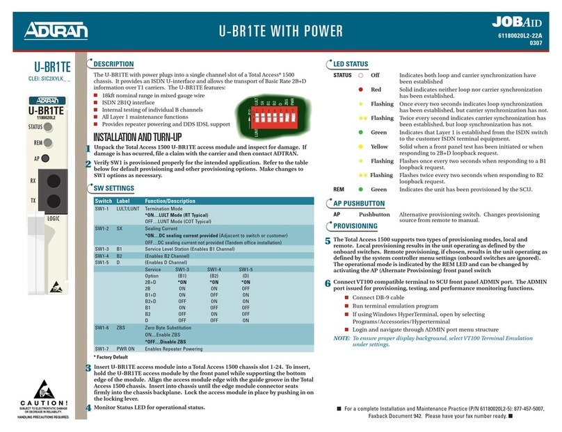
DESCRIPTION
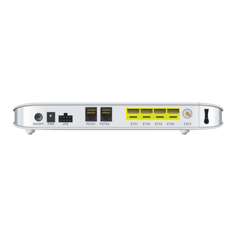
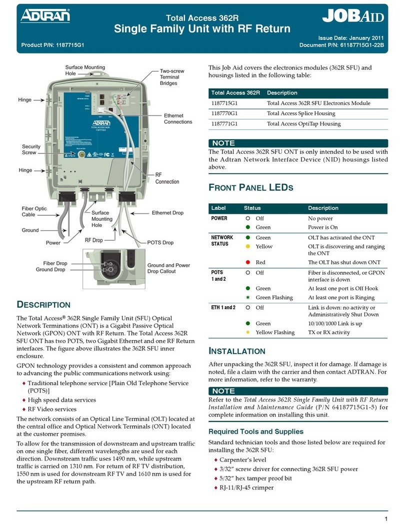
The Total Access®351 2 POTS/1 Ethernet Single Family
Unit (SFU) Optical Network Terminations (ONT) is a Gigabit
Passive Optical Network (GPON) ONT. The 351 SFU ONT
has 2 POTS, and 1 Gigabit Ethernet interface. The figure
above illustrates the SFU ONT inner enclosure. GPON
technology provides a consistent and common approach to
advancing the public communications network using:
•Traditional telephone service is Plain Old Telephone Service
(POTS)
•High speed data services
•Video services
The GPON network consists of an Optical Line Terminal (OLT)
located at the central office and Optical Network Terminals
(ONTs) located at the customer’s premises. Between them lies the
Optical Distribution Network (ODN) consisting of fibers and
passive splitters or couplers.
In order to allow for the transmission of downstream and
upstream traffic on one single fiber, different wavelengths are
used for each direction. Downstream traffic uses 1490 nm, while
upstream traffic is carried on 1310 nm. The ONT employs
optical diplexers to separate the wavelengths.
Surface Mounting
Hole
Surface
Mounting
Hole
Hinge
Hinge
Security
Screw
Tip (Green)
Ring (Red)
Ethernet
Connection
Fiber Optic
Cable
Ground
Power
Ethernet
POTS
Ground and Power
Drop Callout
Ground Drop
Fiber Drop
RING
TIP
RING
TIP
FXS 0/1
FXS 0/2
ETH 0/1
ETH 0/2
TIP RING
ETH 0/1
ETH 0/2
POTS 1
POTS 2
POTS 2
POTS 1
TELCO ACCESS
RF
ETH 1
TOTAL ACCESS 351
1287701G1
12V , 1.25A
POWER
NETWORK STATUS
TELEPHONE TROUBLESHOOTING
1.Identify the bad line.
2.Disconnect the plug from the appropriate POTS jack and plug
any working telephone into that jack.
Ifthe telephone works, there is a problem inside the house.
Ifthe telephone does not work, contact your service provider.
3.Remove the telephone and replace the plug into the POTS jack.
4.Close the unit.
CLEI
TEL. NUMBER
Total Access 351
2 POTS/1 Ethernet SFU ONT
This Job Aid covers the electronics module (SFU ONT) and
housings listed in the following table:
NOTE
The Total Access 351 SFU ONT is only intended to be used with
the ADTRAN Total Access 300 series outdoor NID housing.
FRONT PANEL LEDS
INSTALLATION
NOTE
Refer to the Total Access 351 2 POTS/1 Ethernet SFU ONT
Installation and Maintenance Guide (P/N 61287701G1-5) for
complete information on installing this unit.
After unpacking the SFU ONT, inspect it for damage. If damage is
noted, file a claim with the carrier and then contact ADTRAN. For
more information, refer to the warranty.
Required Tools and Supplies
Standard technician tools and those listed below are required for
installing the SFU ONT:
•Carpenter’s level
•3/32” screw driver for connecting SFU ONT power
•5/32” hex tamper proof bit
•RJ-45/RJ-11 crimper
Total Access 351 Description
1287701G1 Total Access 351 2 POTS/1 Ethernet Single
Family Unit Electronics Module
Total Access SFU
Housings
Description
1187770G1 Total Access 300 Series NID Splice Housing
1187771G1 Total Access 300 Series NID OptiTap Housing
Label Status Description
POWER {
z
Off
Green
No power
Power is On
NETWORK
STATUS
{
z
z
z
Off
Green
Yellow
Red
Administratively Shut Down
Normal
Test in progress
Fault Condition
POTS 1
POTS 2
{
z
2
Off
Green
Green Flashing
Administratively Shut Down
Off Hook
Ringing
ETH 1 {
z
4
Off
Green
Yellow Flashing
Link is down: no activity or
Administratively Shut Down
10/100/1000 Link is up
TX or RX activity
Product P/N: 1287701G1
Issue Date: June 2011
Document P/N: 61287701G1-22A
261287701G1-22A
CAUTION
!
Do not use a knife to cut the opening in the rubber grommets.
This may result in an excessively large hole and compromise the
integrity of the unit allowing moisture into the unit.
Ground Connection
Install the ground connection (see illustration below by
completing the following steps:
1. Remove the rubber grommet from the housing and insert a
#6 solid copper ground wire through the rubber grommet.
2. Using the figure on top of page 3, route the ground wire as
shown and attach it to the ground bar.
3. Replace the rubber grommet in the housing.
4. Route the ground wire 12 inches below finished grade by
the shortest and most direct route to the AC power ground
system Multi Grounded Neutral (MGN) of the customer
premises. Ensure the wire is free of any sharp bends.
5. Attach the ground wire to the side of the subscriber’s
premises with stainless steel half moon clamps or tie-wrap
the ground wire to the riser conduit of the Buried Fiber
Drop.
6. Clean the MGN connector with emery cloth to insure a
stable connection.
7. Attach the ground wire from the SFU ONT to the MGN
connector with the appropriate UL approved ground
clamp/fitting.
8. Coat the connection with a metal corrosion preventative.
9. Attach a Warning Ground Tag to this grounding connection.
Power/Alarm Connections
NOTE
Wiring the Power/Alarm connector improperly could damage
the SFU.
The SFU ONT is supplied with a 7-conductor Euro-style Power/
Alarm connector. To make connections from the UPS to the
power connector complete the following steps:
1. Remove the Power/Alarm Connector by pulling it out of the
electronics module.
123
•A telephony/data communication test set
•PON power meter with wavelength filtering
•Fiberscope or videoscope
•Two #10 screws and appropriate surface anchors for
mounting the SFU ONT
•Assorted tie wraps for securing cabling and wiring
•One RJ-45 plug
•Two RJ-11 plugs (when not using two-screw terminal bridges)
For fiber optic connections, the following are required:
•Fiber splicing tools
•Fiber cleaning materials
•SC/APC fiber connector (Green)
Included with the SFU ONT packaging are 2 two-screw terminal
bridges, fiber cable management and strain relief, a fiber
connector, and electronics/optics. For data, the connection to the
SFU is through the RJ-45 Ethernet connector. For POTS, the
connection is made through two-screw terminal bridges, or RJ-11
connections.
Mount the Enclosure
CAUTION
!
• This equipment must be connected to a known, reliable earth
ground at all times during installation and service. Refer to the
National Electrical Code (NEC) and state/local codes for
details on grounding requirements. A 12 AWG copper ground
conductor shall be used to connect the equipment to earth
ground.
• This equipment must be serviced by authorized service
personnel only. All repair procedures are detailed to allow
sub-assembly level repairs ONLY. Authorized service
personnel should not attempt component level repairs or
circuit modifications to the printed circuit board. Improper
repairs can create a safety hazard.
Complete the following steps to mount the enclosure:
1. Choose a vertical surface near an approved ground, but
away from down spouts, permanent water sprinklers, or
other water sources. The subscriber should have easy access
for testing.
2. Use the top and bottom external mounting holes as a
template to mark fastener locations. Use a level to ensure the
unit is level to prevent warping.
3. Pre-drill the marked locations and install fasteners or
anchors appropriate to the mounting surface (each anchor
rated to 15 lbs minimum).
4. Mount the SFU ONT to the side of the subscriber’s premise.
The Electronics Module is installed in the housing and swings
open on hinges. To release this module, loosen the Security Screw
(refer to the illustration on the first page) and swing the
electronics Module to the left.
61287701G1-22A 3
2. Refer to the illustration at the top of the next column and
“Local Power Source Wiring” section to assist in completing
the next steps.
3. Remove the rubber grommet from the housing and insert
the power and ground cable through the grommet.
4. To terminate the two UPS power leads (Pins 6 and 7) and, if
needed, the five alarm status leads in the power connector,
cut all wires and strip back the insulation. Use a flat head
screwdriver (or similar device) and loosen all the screws on
the Power Alarm Connector. Insert one wire at a time and
tighten the screws to make an electrical contact.
5. Reconnect the Power/Alarm Connector to the bottom of the
Electronics Module.
6. Tie Wrap the wires through the holes just below the Power/
Alarm connector.
7. Replace the rubber grommet while closing the Electronics
Module. This places less stress on the wiring and allows the
Electronics Module to close without pinching any wiring.
Route OptiTap Fiber Drop Cable
Refer to the illustration on the following page for fiber installa-
tions:
1. Place the OptiTap fiber drop in the same rubber grommet
channel as the ground cable. The ground cable should be
“behind” the OptiTap fiber.
2. Connect the OptiTap fiber.
3. Place the OptiTap connector in the cut-out in the housing.
4. Connect the fiber cable to the connector on the bottom of the
Electronics Module.
5. Route the cable so that when the Electronics Module is
closed, the fiber is not pinched.
+ 12VDC
12V RTN
SIG RTN
ON BAT
REP BAT
BATMIS
LOW BAT
7654321
+ 12VDC
12V RTN
SIG RTN
ON BAT
REP BAT
BAT MIS
LOW BAT
7654321
Power/Alarm
Connector
Back of Electronics Module
NOTE
There are wire routing clips on the lower right of the Electronics
Module housing. It is recommended that these not be used. Route
the fiber optics cable so that they are not pinched when the
Electronics Module is closed.
Install Optical Connection
NOTE
Refer to the Total Access 351 2 POTS/1 Ethernet SFU ONT
Installation and Maintenance Guide (P/N 61287701G1-5) for
information on installing the SC/APC optical connection.
To install the optical connector, complete the following:
1. With the electronics module swung open, route the fiber
through the most direct grommet entrance and connect it to
the appropriate SC/APC optical connection.
2. Check that there are no bends in the fiber less than 30 mm
(1.2 inches) radius or 60 mm (approximately 2.5 inches) in
diameter. When the maintenance door is closed, it should
not come in contact with the fiber.
Local Power Source Wiring
Installation of the Local Power Source (LPS) will be dictated by
on-site conditions and local telephone company practices. Refer
to the Total Access 351 2 POTS/1 Ethernet SFU ONT Installation and
Maintenance Guide (P/N 61287701G1-5) for complete information
on connecting to the LPS.
WARNING
!
• Before making any power connections to this equipment, verify
the power is off (fuse removed/breaker tripped).
• The SFU ONT needs to be powered by a UL Listed Power
Supply suitable for the application with Output at LPS Levels.
CAUTION
!
To reduce the risk of fire, use minimum no. 26 AWG
telecommunications line cord.
+ 12VDC
12V RTN
SIG RTN
ON BAT
REPBAT
BATMIS
LOW BAT
7654321
Note: Do not tie wrap
the optical cable.
Route it as shown.
Ground
Rubber
Grommet
Tie Wrap
Opti-Tap
Connector
For more information, refer to the Total Access 351 2 POTS/1 Ethernet SFU ONT Installation
Guide (P/N 61287701G1-5)available online at www.adtran.com.
Warranty: ADTRAN will replace or repair this product within the warranty period if it does not
meet its published specifications or fails while in service. Warranty information can
be found online at www.adtran.com/warranty.
©2011 ADTRAN, Inc. All Rights Reserved. *61287701G1-22A*
NOTE
This equipment should only be operated from the type of
certified/listed power supply recommended by the
manufacturer.
Use the Pin-Out information in the table below as needed.
Install UPS
Installation of the Uninterruptible Power Source (UPS, P/N
1187730G1) will be dictated by on-site conditions and local
telephone company practices.
CAUTION
!
Use caution when routing wires and cables. Avoid severe
bending and routing over sharp edges. Use grommets when
possible to avoid wear on cable insulation.
1. Install the UPS cable that runs from the SFU ONT to the
Power/Alarm connector of the UPS via the customer pro-
vided PVC conduit (or method used by your local telephone
company practice).
2. Swing the electronics module closed and tighten the security
screw with the 5/32 Hex tamper proof bit.
3. If necessary, tie wrap both the #6 ground wire and the UPS
cable run to the Buried Fiber Drop riser conduit.
POTS Connection
The telephone service or POTS connections can be made with
either two-screw terminal bridges, or RJ-11 connectors.
If the two-screw terminal bridges are used the RJ-11 jacks provide
a diagnostic test point. Inserting an RJ-11 jack (i.e., telephone
cable or telephone test set) will connect the telephone set to the
Pin-Out
Power/Alarm
Description Pin-Out
UPS
1LOWBAT 1
2BATMIS 2
3REPBAT 3
4ONBAT 4
5 SIG RTN 5
612VRTN 6
7+12VDC 7
Pin 1
Pin 7
1
2
3
4
5
6
7
UPS Power
Connector
Power/Alarm
Connector
Low Battery
Battery Missing
Replace Battery
On Battery
Signal Return
12 V Return
+12 VDC
(Note: Refer to the sticker on the bottom
of the Power/Alarm Connector if needed)
SFU ONT and also disconnect the subscriber service from the SFU
ONT providing fault isolation to the SFU or premises wiring.
To terminate the POTS lines on the two-screw terminal bridges
complete the following:
1. Trim each wire to length and strip insulation. Identify each
pair in the service cable.
2. Loosen the screws from the TIP (green) and RING (red).
3. Wrap the appropriate wire around the appropriate screw
and tighten the screws to secure the connections.
POTS can also be connected directly to the RJ-11 jack. In this case
the two-screw terminal bridges become isolated and are not used.
Ethernet Connection
If the ONT is going to support up to 1 Gigabit operation (10/100/
1000), the cable used should be rated CAT-6. Strip back the jacket
of the subscriber Ethernet cable and connect the 4-pair twisted
wires to the RJ-45 Plug using an RJ-45 crimper. Insert the termi-
nated RJ-45 jack into the appropriate RJ-45 ETH socket on the SFU
ONT. The table below lists the Ethernet Connections and related
services.
OPERATIONAL SPECIFICATIONS
•Voltage Range: 10VDCto10.5VDC
•Minimum Voltage after Startup: 8.3 VDC
•Maximum Current: 1 Amp
•Power Consumption: 12 Watts
•Operational Temperature: –40°F to 149°F (–40°C to +65°C)
•Storage Temperature: –40°F to 185°F (–40°C to +85°C)
•Relative Humidity: 95%, noncondensing
•Dimensions: 12.7H x 9.9W x 3.8D in (32.3 x 25.1 x 9.7 cm)
•Weight: 13.5 pounds (6.1 kg) ONT and NID combined
MAINTENANCE
The SFU ONT does not require routine hardware maintenance for
normal operation. ADTRAN does not recommend that repairs be
attempted in the field. Repair services may be obtained by
returning the defective unit to ADTRAN. Refer to the warranty
for further information. Field support for software is provided
through upgrade facilities.
SAFETY AND REGULATORY COMPLIANCE
RefertotheSafetyandRegulatoryComplianceNoticeforthis
product(P/N61287701G1‐17)fordetailedsafetyandregulatory
information.
Part Number Description Operation
1287701G1 ETH 1 Data and/or Video
C A U T I O N
C A U T I O N
!
SUBJECT TO ELECTROSTATIC DAMAGE
OR DECREASE IN RELIABILITY.
HANDLING PRECAUTIONS REQUIRED.
ADTRAN CUSTOMER CARE:
From within the U.S. 1.800.726.8663
From outside the U.S. +1 256.963.8716
PRICING AND AVAILABILITY 1.800.827.0807
This manual suits for next models

1

Other ADTRAN Network Hardware manuals

ADTRAN NetVanta 1700801G1 User manual

ADTRAN

ADTRAN NetVanta 1700801G1 User manual

ADTRAN NetVanta 2300 User manual

ADTRAN

ADTRAN NetVanta 2300 User manual

ADTRAN Total Access 1500 Total Reach DDS-DP User manual

ADTRAN

ADTRAN Total Access 1500 Total Reach DDS-DP User manual

ADTRAN HDSL4 User manual

ADTRAN

ADTRAN HDSL4 User manual

ADTRAN Cable T1 ESF CSU ACE User manual

ADTRAN

ADTRAN Cable T1 ESF CSU ACE User manual

ADTRAN SHDSL V.35 LTU User manual

ADTRAN

ADTRAN SHDSL V.35 LTU User manual

ADTRAN 200410L1 User manual

ADTRAN

ADTRAN 200410L1 User manual

ADTRAN ISU 512E User manual

ADTRAN

ADTRAN ISU 512E User manual

ADTRAN 1202295L1 User manual

ADTRAN

ADTRAN 1202295L1 User manual

ADTRAN TOTAL ACCESS 1200 User manual

ADTRAN

ADTRAN TOTAL ACCESS 1200 User manual

ADTRAN TRACER 64 0 Series User manual

ADTRAN

ADTRAN TRACER 64 0 Series User manual

ADTRAN TSU 100 User manual

ADTRAN

ADTRAN TSU 100 User manual

ADTRAN Total Access 3000 Manual

ADTRAN

ADTRAN Total Access 3000 Manual

ADTRAN ISU 512 User manual

ADTRAN

ADTRAN ISU 512 User manual

ADTRAN ESU 120e User manual

ADTRAN

ADTRAN ESU 120e User manual

ADTRAN SFP Series User manual

ADTRAN

ADTRAN SFP Series User manual

ADTRAN Total Access 372E User manual

ADTRAN

ADTRAN Total Access 372E User manual

ADTRAN CenturyLink C424G User manual

ADTRAN

ADTRAN CenturyLink C424G User manual

ADTRAN Total Access 5006 User manual

ADTRAN

ADTRAN Total Access 5006 User manual

ADTRAN NetVanta 8044M User manual

ADTRAN

ADTRAN NetVanta 8044M User manual

ADTRAN FXS/DPO/PLAR 1109403L2 Instruction Manual

ADTRAN

ADTRAN FXS/DPO/PLAR 1109403L2 Instruction Manual

ADTRAN BR1 User manual

ADTRAN

ADTRAN BR1 User manual

ADTRAN Total Access 1500 Dual FXS/DPO User manual

ADTRAN

ADTRAN Total Access 1500 Dual FXS/DPO User manual

ADTRAN 1442890G2 User manual

ADTRAN

ADTRAN 1442890G2 User manual

Popular Network Hardware manuals by other brands

ICP DAS USA ZT-20 IOG Series quick start

ICP DAS USA

ICP DAS USA ZT-20 IOG Series quick start

Avocent MergePoint 5200 Specification sheet

Avocent

Avocent MergePoint 5200 Specification sheet

Russound BGB2 instruction manual

Russound

Russound BGB2 instruction manual

Siemens 2000592-001 user manual

Siemens

Siemens 2000592-001 user manual

TCAM TMAS TMN-10 user manual

TCAM

TCAM TMAS TMN-10 user manual

Concept Pro VHDIPL-V3 Series user manual

Concept Pro

Concept Pro VHDIPL-V3 Series user manual

Juniper SSR1300 Hardware guide

Juniper

Juniper SSR1300 Hardware guide

Matrix Switch Corporation MSC-HD88DES product manual

Matrix Switch Corporation

Matrix Switch Corporation MSC-HD88DES product manual

PMC-Sierra PM5354 Features

PMC-Sierra

PMC-Sierra PM5354 Features

Extreme Networks ExtremeCloud Appliance Series user guide

Extreme Networks

Extreme Networks ExtremeCloud Appliance Series user guide

Alcatel-Lucent vitalqip 5000 quick start guide

Alcatel-Lucent

Alcatel-Lucent vitalqip 5000 quick start guide

Vista Viper quick start guide

Vista

Vista Viper quick start guide

Tektronix 7B87 instruction manual

Tektronix

Tektronix 7B87 instruction manual

Tyco EV 4UA Hybrid Series quick start guide

Tyco

Tyco EV 4UA Hybrid Series quick start guide

Showgear RCA-FSM-18 user manual

Showgear

Showgear RCA-FSM-18 user manual

AvaLAN AW5802mTR-EVAL user manual

AvaLAN

AvaLAN AW5802mTR-EVAL user manual

Panasonic Transistors 2SC4805G Specifications

Panasonic

Panasonic Transistors 2SC4805G Specifications

Patton electronics 2500RC user manual

Patton electronics

Patton electronics 2500RC user manual

manuals.online logo
manuals.online logoBrands
  • About & Mission
  • Contact us
  • Privacy Policy
  • Terms and Conditions

Copyright 2025 Manuals.Online. All Rights Reserved.