manuals.online logo
Brands
  1. Home
  2. •
  3. Brands
  4. •
  5. ADTRAN
  6. •
  7. Network Hardware
  8. •
  9. ADTRAN DSU IV ESP User manual

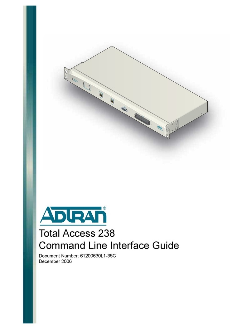
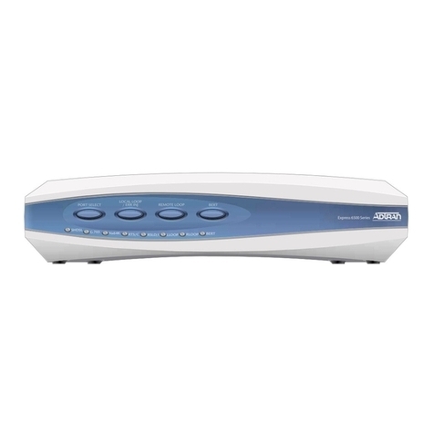
ADTRAN DSU IV ESP User manual

DSU IV ESP
Data Service Unit with Embedded SNMP
USER MANUAL
Part Number Version
1204011L1 DSU IV ESP
1204001L1 ESP 4-wire Switched 56 DBU Card
1204002L1 ESP V.34 DBU Card
1204004L1 ESP ISDN DBU Card
1204005L1 ESP Ethernet Card
61204.011L1-1A
May 1997
Trademark Information:
Hayes is a registered trademark of Hayes Microcomputer Products, Inc.
Openview is a registered trademark of Hewlett-Packard Company.
SunNet Manager is a registered trademark of Sun Microsystems, Inc.
Netview is a registered trademark of IBM.
901 Explorer Boulevard
P.O. Box 140000
Huntsville, AL 35814-4000
Phone: (205) 963-8000
© 1997 ADTRAN, Inc.
All rights reserved.
Printed in USA.
ABOUT THIS MANUAL
This manual is arranged so you can quickly and easily find the information you
need. The following is an overview of the contents of this manual:
• Chapter 1, Introduction, familiarizes you with DDS, Switched 56, SNMP, and
TELNET. This chapter also includes DSU IV highlights and describes the options
that may be purchased for use with the DSU.
• Chapter 2, Installation, describes the DSU connectors (pin assignments are given in
Appendix A) and provides an installation diagram.
• Chapter 3, Operation, explains how to operate your DSU using either the front
panel or a VT 100 terminal interface.
• Chapter 4, Applications, provides examples of some common DSU applications,
including network diagrams.
• Chapter 5, Configuration Overview, explains how to access the DSU configuration
menu, including information on the different configuration methods. This chapter
also provides a front panel menu tree.
• Chapters 6 through 11 provide brief explanations for selections made in the Con-
figuration menus. These chapters are based on the front panel menu branches of
the Configuration menu: Network Options, DTE Options, Test Options, Dial
Options, Management, and Utilities.
• Chapter 12, Testing and Troubleshooting, describes the testing options available
with the DSU IV and gives troubleshooting information.
• Chapter 13, Activating Dial Functions, describes the Dial options available from the
Main menu.
• Chapter 14, Viewing Status Information, provides information on the status menus
available for the base unit as well as the DBU cards.
• Appendix A provides pinouts for the connectors of the DSU and the DBU and
Ethernet cards.
• Appendix B shows the AT commands available for the DSU.
• Appendix C describes the terminal menu interface (accessed through a VT 100
terminal or a TELNET session).
• Appendix D provides information on the unit's configuration profiles.
• Appendix E contains a DSU to modem interconnect diagram for a modem tail
circuit application.
• Appendix F contains product specifications.
Notes provide additional useful information.
Cautions signify information that could prevent service interruption.
Warnings provide information that could prevent damage to the
equipment or endangerment to human life.
FCC regulations require that the following information be provided in this manual:
1. This equipment complies with Part 68 of the FCC rules. On the bottom of the equipment
housing is a label that shows the FCC registration number and ringer equivalence number
(REN) for this equipment. If requested, provide this information to the telephone company.
2. If this equipment causes harm to the telephone network, the telephone company may temporarily
discontinue service. If possible, advance notification is given; otherwise, notification is given
as soon as possible. The telephone company will advise the customer of the right to file a
complaint with the FCC.
3. The telephone company may make changes in its facilities, equipment, operations, or
procedures that could affect the proper operation of this equipment; advance notification and
the opportunity to maintain uninterrupted service are given.
4. If experiencing difficulty with this equipment, please contact ADTRAN for repair and
warranty information. The telephone company may require this equipment to be
disconnected from the network until the problem is corrected, or it is certain the equipment is
not malfunctioning.
5. This unit contains no user-serviceable parts.
6. An FCC compliant telephone cord with a modular plug is provided with this equipment. In
addition, an FCC compliant cable appropriate for the dial backup option ordered is provided
with this equipment. This equipment is designed to be connected to the telephone network or
premises wiring using an FCC compatible modular jack, which is Part 68 compliant.
7. The following information may be required when applying to the local telephone company for
leased line facilities:
Service Digital Facility Service Order Network
Type Interface Code Code Jacks
2.4 kbps Digital Interface 04DU5-24 6.0F RJ-48S
4.8 kbps Digital Interface 04DU5-48 6.0F RJ-48S
9.6 kbps Digital Interface 04DU5-96 6.0F RJ-48S
19.2 kbps Digital Interface 04DU5-19 6.0F RJ-48S
38.4 kbps Digital Interface 04DU5-38 6.0F RJ-48S
56 kbps Digital Interface 04DU5-56 6.0F RJ-48S
64 kbps Digital Interface 04DU5-64 6.0F RJ-48S
8. The following information may be required when applying to the local telephone company for
a dial-up line for the V.34:
Service REN FIC USOC
Type
Loop Start (V.34) 0.8B/0.4A 02LS2 RJ-11C
9. The REN is useful in determining the quantity of devices you may connect to your telephone
line and still have all of those devices ring when your number is called. In most areas, the sum
of the RENs of all devices should not exceed five. To be certain of the number of devices you
may connect to your line as determined by the REN, call your telephone company to
determine the maximum REN for your calling area.
10.This equipment may not be used on coin service provided by the telephone company.
Connection to party lines is subject to state tariffs. (Contact your state public utility
commission or corporation commission for information.)
FEDERAL COMMUNICATIONS COMMISSION
RADIO FREQUENCY INTERFERENCE STATEMENT
This equipment has been tested and found to comply with the limits for a Class A digital
device, pursuant to Part 15 of the FCC rules. These limits are designed to provide reason-
able protection against harmful interference when the equipment is operated in a commercial
environment. This equipment generates, uses, and can radiate radio frequency energy and,
if not installed and used in accordance with the instruction manual, may cause harmful
interference to radio frequencies. Operation of this equipment in a residential area is likely
to cause harmful interference in which case the user will be required to correct the interfer-
ence at his own expense.
Shielded cables must be used with this unit to ensure compliance with Class A FCC limits.
Change or modifications to this unit not expressly approved by the
party responsible for compliance could void the user's authority to
operate the equipment.
CANADIAN EMISSIONS REQUIREMENTS
This digital apparatus does not exceed the Class A limits for radio noise emissions
from digital apparatus as set out in the interference-causing equipment standard
entitled "Digital Apparatus," ICES-003 of the Department of Communications.
Cet appareil nuerique respecte les limites de bruits radioelectriques applicables aux
appareils numeriques de Class A prescrites dans la norme sur le materiel brouilleur:
"Appareils Numeriques," NMB-003 edictee par le ministre des Communications.
CANADIAN EQUIPMENT LIMITATIONS
Notice: The Canadian Industry and Science Canada label identifies certified
equipment. This certification means that the equipment meets certain telecom-
munications network protective, operational, and safety requirements. The
Department does not guarantee the equipment will operate to the user's satisfac-
tion.
Before installing this equipment, users should ensure that it is permissible to be
connected to the facilities of the local telecommunications company. The equip-
ment must also be installed using an acceptable method of connection. In some
cases, the company's inside wiring associated with a single line individual
service may be extended by means of a certified connector assembly (telephone
extension cord). The customer should be aware that compliance with the above
conditions may not prevent degradation of service in some situations.
Repairs to certified equipment should be made by an authorized Canadian
maintenance facility designated by the supplier. Any repairs or alterations made
by the user to this equipment, or equipment malfunctions, may give the telecom-
munications company cause to request the user to disconnect the equipment.
Users should ensure for their own protection that the electrical ground connec-
tions of the power utility, telephone lines and internal metallic water pipe
system, if present, are connected together. This precaution may be particularly
important in rural areas.
Caution: Users should not attempt to make such connections themselves, but
should contact the appropriate electric inspection authority, or an electrician, as
appropriate.
The Load Number (LN) assigned to each terminal device denotes the percentage
of the total load to be connected to a telephone loop which is used by the device,
to prevent overloading. The termination on a loop may consist of any combina-
tion of devices subject only to the requirement that the total of the Load Num-
bers of all devices does not exceed 100.
ISDN Service Ordering Information for the ADTRAN DSU IV ESP With ISDN Dial
Backup
For ADTRAN DSU IV ESP ISDN applications, the following guide can be used as
an aid in ordering basic ISDN service from your local telephone company. The
ADTRAN DSU IV ESP ISDN includes NT1 and Terminal adapter functionality and
supports data rates up to 64 kbps.
Request an ISDN Basic Rate Interface (BRI) line with the following features:
U-interface reference point
2B1Q line coding
1B+D Service (supports up to 64 kbps)
The DSU IV ESP ISDN supports the following switch types and software
protocols:
AT&T 5ESS Custom, 5E6 and later software, National ISDN-1
NT1 DMS-100 BCS-32 and later software (Pvc1), National ISDN-1 (Pvc2)
Siemens EWSD National ISDN-1
Request that the ISDN line allocate one DYNAMIC Terminal Endpoint Identifier
(TEI) for the number.
For service offered from an AT&T 5ESS, request a point-to-point line with the
following features:
Feature: Value
B1 Service: On Demand (DMD)
Data Line Class: Point-to-Point
Maximum B Channels: 1 (1B+D)
Circuit Switched Data (CSD) Bearer Channels: Any
Number of CSD Calls: 1 (1B+D)
Terminal Type: Type A
Turn the Following Features Off:
Packet Mode Data
Multi-line Hunt
Multiple Call Appearances
Electronic Key Telephone Sets (EKTS)
Shared Dictionary Numbers
Accept Special Type of Number
Intercom Groups
Network Resource Selector (Modem Pools)
Message Waiting
Hunting
InterLata Competition
For service offered from a Northern Telecom DMS-100, request a Point-to-Point
Multi-Point line with the following features:
Line Type: Basic Rate, Functional
Electronic Key Telephone Sets (EKTS): No
Call Appearance Handling (CACH): No
Non-Initializing Terminal: No
Circuit Switched Service: Yes
Packet Switched Service: No
TEI: Dynamic
Bearer Service: Circuit Switched voice and data permitted on any B channel (packet mode
data not permitted)
Table of Contents
Table of Contents
Table of Contents
Chapter 1. Introduction
Product Overview .................................................................................................................. 1
DDS Operation ........................................................................................................................ 3
Switched 56 Operation ...........................................................................................................4
SNMP ....................................................................................................................................... 4
Network Manager ............................................................................................. 4
Agent................................................................................................................... 4
MIB ...................................................................................................................... 4
TELNET.................................................................................................................................... 5
Dial Backup Operation .......................................................................................................... 5
ESP Dial Backup Options ............................................................................................... 5
4-Wire Switched 56 Card ........................................................................................ 5
V.34 Card ................................................................................................................... 6
ISDN Card ................................................................................................................. 6
Warranty and Customer Service .......................................................................................... 6
Chapter 2. Installation
Unpack, Inspect, Power Up................................................................................................... 7
Receipt Inspection ........................................................................................................... 7
ADTRAN Shipments Include ................................................................................. 7
Customer Provides................................................................................................... 8
Power Up .......................................................................................................................... 8
Rear Panel ................................................................................................................................ 9
DBU and Ethernet Card Slots ...................................................................................... 10
Telco Connector ............................................................................................................. 10
Network Interface Connection .................................................................................... 10
EIA-232 and V.35 Connectors ...................................................................................... 10
DTE Data Connection/Primary DTE ......................................................................... 10
Control Port ....................................................................................................................11
Chapter 3. Operation
Front Panel............................................................................................................................. 13
LCD Window ................................................................................................... 13
Enter .................................................................................................................. 13
Keypad.............................................................................................................. 13
Shift ................................................................................................................... 13
61204.011L1-1 DSU IV ESP User Manual i
Table of Contents
ii DSU IV ESP User Manual 61204.011L1-1
Cancel ............................................................................................................... 14
Up and Down Arrows .................................................................................... 14
LED Descriptions ............................................................................................ 14
Front Panel Menu Navigation ..................................................................................... 17
Front Panel Menu Structure......................................................................................... 18
Main Menu .............................................................................................................. 18
Status................................................................................................................. 18
Test .................................................................................................................... 18
Configuration .................................................................................................. 19
Dial .................................................................................................................... 19
VT 100 Terminal Connection and Operation .................................................................... 20
Chapter 4. Applications
LAN Application with SNMP/TELNET Management .................................................. 23
Minimum Configuration Requirements for SNMP/TELNET Access................... 24
Interface ............................................................................................................ 24
IP Address ........................................................................................................ 24
Subnet Mask..................................................................................................... 24
Gateway IP Address (if required) ................................................................. 24
Special Features of this Application ........................................................................... 24
Dial Backup Application...................................................................................................... 26
Entering Dial Backup Mode......................................................................................... 26
Operation During Critical Times ......................................................................... 26
Loss of Sealing Current .................................................................................. 26
Out of Service (OOS) Signal .......................................................................... 26
No Receive Signal ........................................................................................... 27
All 1s or all 0s Condition................................................................................ 27
Answer Always ............................................................................................... 27
Operation During Noncritical Times .................................................................. 27
Weekend and Time of Day Lockout ............................................................. 27
Conditions for Returning to the DDS Circuit............................................................ 27
Chapter 5. Configuration Overview
Configuration Methods ....................................................................................................... 29
AT Commands ............................................................................................................... 33
V.25 bis Commands ...................................................................................................... 34
SDLC Option ........................................................................................................... 34
Character Format ............................................................................................ 34
Command Structure ....................................................................................... 34
Bi-Sync Option ........................................................................................................ 34
Table of Contents
61204.011L1-1 DSU IV ESP User Manual iii
Character Format ............................................................................................ 34
Command Structure ....................................................................................... 34
Asynchronous Option ........................................................................................... 35
Character Format ............................................................................................ 35
Command Structure ....................................................................................... 35
Command Descriptions......................................................................................... 35
Syntax and Possible Responses ............................................................................ 36
CNL (Configuration Local) ............................................................................ 36
CNR (Configuration Remote) ....................................................................... 36
Chapter 6. Configuring Network Options
Network Options .................................................................................................................. 37
Loop Rate ........................................................................................................................ 39
Network Address .......................................................................................................... 40
Remote Configuration .................................................................................................. 40
Network Type ................................................................................................................ 40
Clock Source ................................................................................................................... 40
Chapter 7. Configuring DTE Option
DTE Options .......................................................................................................................... 41
DTE Rate ......................................................................................................................... 45
Connector Type ............................................................................................................. 46
Data Format.................................................................................................................... 46
DTE Command Option................................................................................................. 46
Transmit Clock............................................................................................................... 46
Clear to Send (CS) Options .......................................................................................... 47
Anti-Stream .................................................................................................................... 47
CD Options ..................................................................................................................... 48
Data Terminal Ready (TR) Options ............................................................................ 48
Data Set Ready (SR) Options ....................................................................................... 48
Chapter 8. Configuring Test Options
Test Options ........................................................................................................................... 49
Test Timeout................................................................................................................... 50
Remote Digital Loopback (RDL) ................................................................................. 50
EIA LLB........................................................................................................................... 51
EIA RLB .......................................................................................................................... 51
DBU Answer Test .......................................................................................................... 51
Table of Contents
iv DSU IV ESP User Manual 61204.011L1-1
Chapter 9. Configuring Dial Options
Dial Options .......................................................................................................................... 53
Phone Numbers .................................................................................................................... 55
ISDN Dial Backup ......................................................................................................... 55
Setting the Service Profile Identifier (SPID) ................................................ 55
Setting the Local Directory (LOC) Number ................................................ 55
SW56 Auto Answer .............................................................................................................. 56
DBU Options ......................................................................................................................... 56
Standard DBU Options ................................................................................................. 56
Automatic DBU ...................................................................................................... 56
Number to Dial ....................................................................................................... 56
Originate/Answer ................................................................................................. 56
DBU Criteria ........................................................................................................... 57
When Out of Service (OOS) ........................................................................... 57
No Receive (RX) Signal .................................................................................. 57
No Sealing Current ......................................................................................... 57
When all 1s/0s ................................................................................................. 57
Answer Always ............................................................................................... 57
Weekend Lockout............................................................................................ 57
Daily Lockout .................................................................................................. 57
Lockout Start.................................................................................................... 58
Lockout End ..................................................................................................... 58
Auto Restore ........................................................................................................... 58
Redial Counter ........................................................................................................ 58
Fail Timer ................................................................................................................ 59
Wait to Redial ......................................................................................................... 59
DBU Options for S4W Card ......................................................................................... 62
Network Type .................................................................................................. 62
DBU Options for V.34 Card ......................................................................................... 62
Error Control .................................................................................................... 62
Flow Control .................................................................................................... 62
Compression .................................................................................................... 62
DBU Options for ISDN Card ....................................................................................... 64
Switch Type ...................................................................................................... 64
DBU Passcode ....................................................................................................................... 64
Chapter 10. Configuring Management Functions
Interface .......................................................................................................................... 66
Control Rate ................................................................................................................... 66
IP Options ....................................................................................................................... 66
Unit IP Address ............................................................................................... 66
Table of Contents
61204.011L1-1 DSU IV ESP User Manual v
Subnet Mask.....................................................................................................66
Gateway IP Address.......................................................................................66
IP Security........................................................................................................66
IP Filter Address..............................................................................................66
SNMP Options...............................................................................................................67
Get Community...............................................................................................67
Set Community................................................................................................67
Trap Community.............................................................................................67
SNMP Traps.....................................................................................................67
Trap IPAddress...............................................................................................67
System Name, Contact, and Location..........................................................68
Authentication Traps......................................................................................68
TELNET Options...........................................................................................................68
TELNET Password..........................................................................................68
TELNET Timeout............................................................................................68
Entering Letters Using the Front Panel.............................................................................69
Chapter 11. Configuring Unit Utilities
Manual Command........................................................................................................72
Time/Date......................................................................................................................74
Software Revision..........................................................................................................74
LAN MAC Address......................................................................................................74
Serial Number................................................................................................................74
Chapter 12. Testing and Troubleshooting
Test Overview........................................................................................................................75
Initiating a Test..............................................................................................................76
Test Status Display........................................................................................................77
Exiting a Test..................................................................................................................77
Troubleshooting....................................................................................................................79
Messages from the DSU/CSU.....................................................................................79
Troubleshooting New Installs.....................................................................................80
Test Sequence for Troubleshooting New Installs or Existing Circuits...........81
Local Unit Diagnostics.........................................................................................................82
DTE & Loop (LL)...........................................................................................................84
Loop Only (RT)..............................................................................................................85
DTE Only........................................................................................................................86
DTE With Test Pattern..................................................................................................87
Test Pattern.....................................................................................................................89
Self Test...........................................................................................................................90
Table of Contents
vi DSU IV ESP User Manual 61204.011L1-1
Remote Unit Diagnostics ..................................................................................................... 91
DBU Connection ................................................................................................................... 93
Chapter 13. Activating Dial Functions
Dial Options .......................................................................................................................... 95
Answer Unit Connected to DDS Line ................................................................. 96
Dial Backup ...................................................................................................... 96
Originate Unit Connected to DDS Line .............................................................. 96
Dial Backup ...................................................................................................... 96
Stay on Leased ................................................................................................. 96
DBU Online Test .............................................................................................. 97
Dial Options During Dial Backup........................................................................ 97
Hang Up ........................................................................................................... 97
Stay On Line..................................................................................................... 97
Chapter 14. Viewing Status Information
Status ...................................................................................................................................... 99
Network Rate, DTE Rate, and Data Format ....................................................... 99
Dial Backup Information ..................................................................................... 100
Type of Dial Backup Service ........................................................................ 100
Current Status of Dial Backup Mode ......................................................... 100
DSU Operation and Network Status ................................................................. 102
Current DSU IV ESP Status ......................................................................... 102
Current DDS Network Status...................................................................... 102
DTE Control Leads and Status ........................................................................... 103
Appendix A. Pinouts ........................................................................................................ 105
Appendix B. AT Commands ............................................................................................111
Appendix C. Terminal Menu Structure ........................................................................ 113
Appendix D. Configuration Profiles ............................................................................ 129
Appendix E. DSU to Modem Interconnect .................................................................. 133
Appendix F. Specifications Summary........................................................................... 135
Glossary ............................................................................................................................... 139
Index ..................................................................................................................................... 147
Table of Contents
61204.011L1-1 DSU IV ESP User Manual vii
List of Tables
Table 6-A Network Options AT Commands ................................................................. 38
Table 7-A DTE Options AT Commands ......................................................................... 43
Table 7-B Short and Long Delays at Different Operating Speeds ............................. 47
Table 8-A Test Options AT Commands.......................................................................... 50
Table 9-A AT Commands for Storing Phone Numbers ............................................... 55
Table 9-B DBU Options AT Commands for All Models ............................................. 60
Table 9-C DBU Options AT Commands for V.34 Card ................................................ 63
Table 11-A Manual Commands ........................................................................................ 73
Table 12-A Messages from the DSU/CSU ....................................................................... 79
Table 12-B Troubleshooting New Installs ....................................................................... 80
Table 12-C Test AT Commands ......................................................................................... 82
Table 12-D DTE With Test Pattern Commands............................................................... 83
Table 12-E Remote Tests and AT Commands ................................................................. 91
Table A-A Pin Assignments for Telco Connector ........................................................ 106
Table A-B Pin Assignments for ESP DBU Card Connectors ..................................... 106
Table A-C Pin Assignments for Primary EIA-232 Connector ................................... 107
Table A-D Pin Assignments for Primary V.35 Connector .......................................... 108
Table A-E Pin Assignments for Control Connector.................................................... 108
Table A-F Pin Assignments for 10baseT Connector ................................................... 109
Table B-A AT Commands ................................................................................................ 111
Table C-A Terminal Main Menu Dial Selection ............................................................114
Table D-A Configuration Profiles .................................................................................. 130
List of Figures
Figure 1-1 Typical Point-to-Point Application for DSU IV ESP .................................... 3
Figure 2-1 DSU IV ESP Rear View ..................................................................................... 9
Figure 3-1 DSU IV ESP Front Panel ................................................................................. 15
Figure 3-2 Example of Basic Menu Navigation ............................................................. 17
Figure 3-3 Terminal Interface Main Menu (SW56 Mode) ............................................ 21
Figure 4-1 SLIP/PPP LAN Application with SNMP/TELNET Management .......... 25
Figure 4-2 Ethernet LAN Application with SNMP/TELNET Management............. 25
Figure 4-3 Dial Backup Application ................................................................................ 28
Figure 5-1 Front Panel Configuration Menu Tree ......................................................... 31
Figure 6-1 Network Options Menu Tree......................................................................... 39
Figure 7-1 DTE Options Menu Tree ................................................................................ 42
Figure 8-1 Test Options Menu Tree ................................................................................. 49
Figure 9-1 Dial Options Configuration Menu Tree ....................................................... 54
Figure 10-1 Management Menu Tree ................................................................................ 65
Figure 11-1 Utilities Menu Tree.......................................................................................... 71
Table of Contents
viii DSU IV ESP User Manual 61204.011L1-1
Figure 12-1 Normal Operation Before Initiating Loopback Test................................... 75
Figure 12-2 Initiating a Test ................................................................................................ 76
Figure 12-3 Sample Test Status Displays .......................................................................... 77
Figure 12-4 Complete Test Menu ....................................................................................... 78
Figure 12-5 DTE & Loop Test ............................................................................................. 84
Figure 12-6 Loop Only Test ................................................................................................ 85
Figure 12-7 DTE Only Test Diagram ................................................................................. 86
Figure 12-8 DTE with Test Pattern..................................................................................... 87
Figure 12-9 Test Pattern Only ............................................................................................. 89
Figure 12-10 V.54 RDL with Test Pattern ........................................................................... 91
Figure 12-11 Initiating a Remote Test ................................................................................. 92
Figure 12-12 DBU Connection Test .................................................................................... 93
Figure 12-13 Initiating a DBU Connection Test ................................................................ 94
Figure 13-1 Dial Options Menu (SW56) ............................................................................ 95
Figure 13-2 Dial Options Menu (Dedicated) .................................................................... 96
Figure 14-1 Status Display .................................................................................................. 99
Figure C-1 Terminal Interface Main Menu.....................................................................114
Figure C-2 Terminal Menu Tree .......................................................................................115
Figure C-3 Status Menu ....................................................................................................117
Figure C-4 Remote Configuration Options ....................................................................118
Figure C-5 Main Configuration Menu ............................................................................119
Figure C-6 DSU Configuration Menu ............................................................................ 120
Figure C-7 S4W Dial Backup ........................................................................................... 121
Figure C-8 Management Menu ....................................................................................... 122
Figure C-9 SNMP Management Menu .......................................................................... 123
Figure C-10 Utility Menu................................................................................................... 124
Figure C-11 Local Test Options Menu ............................................................................. 125
Figure C-12 Remote Test Options Menu ......................................................................... 126
Figure C-13 SW56 Dialing Menu ...................................................................................... 127
Figure C-14 Dial ESP DBU Menu ..................................................................................... 128
Figure E-1 DSU to Modem Interconnect ....................................................................... 133
61204.011L1-1 DSU IV ESP User Manual 1
Chapter 1. Introduction
Chapter1
Introduction
PRODUCT OVERVIEW
The ADTRAN DSU IV ESP (data service unit with embedded
SNMP) provides a reliable, high speed data connection for
customer data terminal equipment (DTE) through digital data
service (DDS) lines. The DSU IV ESP has an embedded SNMP
(simple network management protocol) agent that provides
complete SNMP access to the unit through an integral SLIP or
PPP async port. The DSU IV ESP's unique modular approach
provides optional 10baseT ethernet access for SNMP. Also,
optional modular ESP DBU cards provide automatic or manual
dial backup for the dedicated circuit.
The following are features of the DSU IV:
• DDS rates supported from 2.4 to 64 kbps including 19.2 and
38.4
• 4-wire Switched 56 (SW56) operation
• Embedded SNMP and TELNET
• Control port provides SLIP and Async PPP access to SNMP or
VT 100 terminal configuration
• Two ESP option slots
• 10baseT ethernet SNMP port available with ESP ethernet Card
• Automatic or manual DBU
• DBU available with ESP DBU cards; options include 4-wire
Switched 56, V.34, and ISDN
• Time of day and weekend DBU lockout options
2DSU IV ESP User Manual 61204.011L1-1
Chapter 1. Introduction
The DSU IV ESP provides both V.35 and EIA-232 electrical and
physical DTE interfaces to accommodate a variety of applica-
tions.
To ensure a reliable connection, the unit features an extended
receiver capability which permits operation over long loops
(3.4 miles or 5.5 km of 26 AWG at 56 kbps).
The ESP 4-wire SW56 DBU card and the base unit's integrated
SW56 capabilities are compatible with AT&T Accunet and Sprint
SW56 type services. The V.34 DBU card allows switched backup
over the public switched telephone network (PSTN). The ESP
ISDN 1B+D card is compatible with National ISDN and supports
a U- interface to the Basic Rate ISDN.
Figure 1-1 shows a typical point-to-point application for the DSU
IV ESP.

Other manuals for DSU IV ESP

2

This manual suits for next models

5

Other ADTRAN Network Hardware manuals

ADTRAN TRACER 4x03 User manual

ADTRAN

ADTRAN TRACER 4x03 User manual

ADTRAN DDM+ HTU-C M User manual

ADTRAN

ADTRAN DDM+ HTU-C M User manual

ADTRAN Total Access 324E User manual

ADTRAN

ADTRAN Total Access 324E User manual

ADTRAN 6540 Product manual

ADTRAN

ADTRAN 6540 Product manual

ADTRAN TRACER 4106 Plan User guide

ADTRAN

ADTRAN TRACER 4106 Plan User guide

ADTRAN TRACER 5045 User manual

ADTRAN

ADTRAN TRACER 5045 User manual

ADTRAN U-BR1TE User manual

ADTRAN

ADTRAN U-BR1TE User manual

ADTRAN Ethernet Over Bonded Copper MX3112 User manual

ADTRAN

ADTRAN Ethernet Over Bonded Copper MX3112 User manual

ADTRAN DSX 1 User manual

ADTRAN

ADTRAN DSX 1 User manual

ADTRAN NetVanta 838 Operation manual

ADTRAN

ADTRAN NetVanta 838 Operation manual

ADTRAN Total Access 1500 Dual FXS/DPO User manual

ADTRAN

ADTRAN Total Access 1500 Dual FXS/DPO User manual

ADTRAN 6540 Instruction Manual

ADTRAN

ADTRAN 6540 Instruction Manual

ADTRAN CenturyLink C424G User manual

ADTRAN

ADTRAN CenturyLink C424G User manual

ADTRAN SDX 621i XGS-PON ONT User manual

ADTRAN

ADTRAN SDX 621i XGS-PON ONT User manual

ADTRAN SDX 611 GPON SFU ONT User manual

ADTRAN

ADTRAN SDX 611 GPON SFU ONT User manual

ADTRAN Total Access 300 Series Product manual

ADTRAN

ADTRAN Total Access 300 Series Product manual

ADTRAN Total Access 300 Series Product manual

ADTRAN

ADTRAN Total Access 300 Series Product manual

ADTRAN 1202803L1 User manual

ADTRAN

ADTRAN 1202803L1 User manual

ADTRAN jobAid User manual

ADTRAN

ADTRAN jobAid User manual

ADTRAN 1442823F1 User manual

ADTRAN

ADTRAN 1442823F1 User manual

ADTRAN NetVanta SHDSL Network Interface Module User manual

ADTRAN

ADTRAN NetVanta SHDSL Network Interface Module User manual

ADTRAN TR OCU DP Instruction Manual

ADTRAN

ADTRAN TR OCU DP Instruction Manual

ADTRAN ISU 512E User manual

ADTRAN

ADTRAN ISU 512E User manual

ADTRAN NetVanta 900 Series Manual

ADTRAN

ADTRAN NetVanta 900 Series Manual

Popular Network Hardware manuals by other brands

RuggedCom RUGGED VDSL RS910L installation guide

RuggedCom

RuggedCom RUGGED VDSL RS910L installation guide

Patton electronics OnSite 2884 Getting started guide

Patton electronics

Patton electronics OnSite 2884 Getting started guide

RFID HF-3600E-RS232 product manual

RFID

RFID HF-3600E-RS232 product manual

Nortel 2340 Configuration guide

Nortel

Nortel 2340 Configuration guide

Raisecom Gazelle S1512i-4GF-8GE-PWR user manual

Raisecom

Raisecom Gazelle S1512i-4GF-8GE-PWR user manual

Aetina DeviceEdge AGX Orin Series user manual

Aetina

Aetina DeviceEdge AGX Orin Series user manual

ADPRO iFT Series Hardware installation manual

ADPRO

ADPRO iFT Series Hardware installation manual

EverFocus VANGUARD II 4x2H Quick installation guide

EverFocus

EverFocus VANGUARD II 4x2H Quick installation guide

Billion BiPAC 2071 White paper

Billion

Billion BiPAC 2071 White paper

Wisenet XRN-2010 Quick manual

Wisenet

Wisenet XRN-2010 Quick manual

Ericsson MINI-LINK 6351 Technical description

Ericsson

Ericsson MINI-LINK 6351 Technical description

Compatible Systems 8 Port 10 RIOP installation guide

Compatible Systems

Compatible Systems 8 Port 10 RIOP installation guide

Paradyne Jetstream CPX-1000 installation guide

Paradyne

Paradyne Jetstream CPX-1000 installation guide

JVC Milestone VR-N1600 Brochure & specs

JVC

JVC Milestone VR-N1600 Brochure & specs

ATC ODB-48/OSB installation manual

ATC

ATC ODB-48/OSB installation manual

Amperes iPX Series instruction manual

Amperes

Amperes iPX Series instruction manual

GMI Tricon instruction manual

GMI

GMI Tricon instruction manual

WIN Enterprises PL-80720 user manual

WIN Enterprises

WIN Enterprises PL-80720 user manual

manuals.online logo
manuals.online logoBrands
  • About & Mission
  • Contact us
  • Privacy Policy
  • Terms and Conditions

Copyright 2025 Manuals.Online. All Rights Reserved.