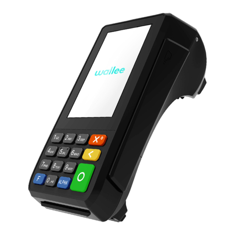
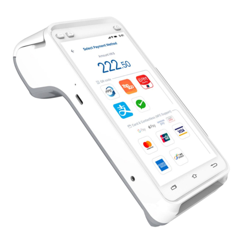
Advanced Card ACR890 User manual

Subject to change without prior notice info@acs.com.hk
www.acs.com.hk
Reference Manual V1.03
ACR890
All-in-OneMobile
SmartCardTerminal

ACR890 – Reference Manual info@acs.com.hk
Version 1.03 www.acs.com.hk
Page 2 of 90
Table of Contents
1.0. Introduction .............................................................................................................5
2.0. Features ...................................................................................................................6
3.0. File and Directory Structure ...................................................................................7
4.0. Pseudo APDU commands for Contactless Interface ............................................8
4.1. Get Data.................................................................................................................................8
4.2. PICC Commands (T=CL Emulation) for MIFARE® Classic 1K/4K Memory Cards ..............9
4.2.1. Load Authentication Keys .............................................................................................9
4.2.2. Authentication for MIFARE Classic 1K/4K..................................................................10
4.2.3. Read Binary Blocks.....................................................................................................13
4.2.4. Update Binary Blocks..................................................................................................14
4.2.5. Value Block Operation (Increment, Decrement, Store) ..............................................15
4.2.6. Read Value Block........................................................................................................16
4.2.7. Copy Value Block........................................................................................................17
5.0. Keypad APIs ..........................................................................................................18
5.1. Open keypad file descriptor.................................................................................................18
5.2. Close Keypad file descriptor................................................................................................18
5.3. Get current keypad state .....................................................................................................19
5.4. Set Power Button Working Mode ........................................................................................19
5.5. Get Power Button Working Mode........................................................................................20
6.0. Backlight Control APIs..........................................................................................22
6.1. Get current backlight level...................................................................................................22
6.2. Set backlight level................................................................................................................23
7.0. Battery and Charger APIs.....................................................................................24
7.1. Get battery and charger state..............................................................................................24
8.0. LED Control APIs...................................................................................................25
8.1. Set LED state.......................................................................................................................25
8.2. Get LED’s blinking status.....................................................................................................26
9.0. GPRS Module Power Management APIs..............................................................27
9.1. Power on GPRS ..................................................................................................................27
9.2. Power off GPRS ..................................................................................................................28
9.3. Set pppd connect parameter ...............................................................................................29
9.4. Set pppd dialer parameter...................................................................................................30
9.5. Start up pppd process..........................................................................................................31
9.6. Turn off pppd process..........................................................................................................32
9.7. Transmit one AT command .................................................................................................34
9.8. Get IMEI Serial Number.......................................................................................................35
10.0. Audio (ALSA) APIs ................................................................................................36
10.1. Get system audio volume....................................................................................................36
10.2. Set system audio volume.....................................................................................................37
10.3. Sound playback ...................................................................................................................38
10.4. Speaker Sound Control .......................................................................................................39
11.0. Firmware APIs .......................................................................................................40
11.1. Get firmware version............................................................................................................40
12.0. Thermal Printer APIs.............................................................................................41
12.1. Open the printer port............................................................................................................41
12.2. Close the printer port ...........................................................................................................42

ACR890 – Reference Manual info@acs.com.hk
Version 1.03 www.acs.com.hk
Page 3 of 90
12.3. Reset the printer ..................................................................................................................43
12.4. Feed paper to printer ...........................................................................................................44
12.5. Set line space in Standard Mode.........................................................................................45
12.6. Print string in Standard Mode..............................................................................................46
12.7. Print string in Page Mode ....................................................................................................47
12.8. Print data array in Standard Mode.......................................................................................49
12.9. Print data array in Page Mode.............................................................................................50
12.10. Print an image......................................................................................................................51
12.11. Get status of the printer .......................................................................................................52
12.12. Initialize freetype library.......................................................................................................54
12.13. Set the character size..........................................................................................................55
12.14. Get glyph image and printing...............................................................................................56
12.15. Release freetype library.......................................................................................................57
13.0. Wireless LAN Module Control APIs......................................................................58
13.1. Power on wireless LAN module...........................................................................................58
13.2. Power off wireless LAN module...........................................................................................59
14.0. Contact Smart Card Reader APIs.........................................................................60
14.1. Open the contact card reader module.................................................................................60
14.2. Close the contact card reader module.................................................................................61
14.3. Check if a contact card is present .......................................................................................62
14.4. Power on a contact smart card............................................................................................63
14.5. Power off a contact smart card............................................................................................64
14.6. Send PPS to contact smart card .........................................................................................65
14.7. Contact smart card APDU transfer......................................................................................66
15.0. Contactless Reader APIs......................................................................................68
15.1. Open the contactless reader module...................................................................................68
15.2. Close the contactless reader module ..................................................................................69
15.3. Read a contactless card......................................................................................................70
15.4. Activate the contactless card...............................................................................................71
15.5. Deactivate the contactless card...........................................................................................72
15.6. Contactless card data transfer.............................................................................................73
15.7. FeliCa card data transfer.....................................................................................................74
15.8. Contactless card reader antenna control.............................................................................75
16.0. Magnetic Stripes Card APIs..................................................................................79
16.1. Get track data from a magnetic stripe card .........................................................................79
17.0. Error code description APIs .................................................................................81
17.1. Get the error description by a given error code...................................................................81
18.0. INI file parser APIs.................................................................................................82
18.1.Get an ini keyword value .....................................................................................................82
18.2. Set a ini keyword value........................................................................................................83
18.3. Add a ini keyword ................................................................................................................84
18.4. Set hardware value according to all keywords in /etc/config.ini ..........................................85
18.5. Set hardware value according to the specified keyword.....................................................86
19.0. Power Management APIs......................................................................................87
19.1. Set system sleep timeout.....................................................................................................87
19.2. Get system sleep time.........................................................................................................87
19.3. Enable or disable system auto sleep...................................................................................88

ACR890 – Reference Manual info@acs.com.hk
Version 1.03 www.acs.com.hk
Page 4 of 90
List of Tables
Table 1 : MIFARE 1K Memory Map......................................................................................................11
Table 2 : MIFARE 4K Memory Map......................................................................................................11
Table 3 : MIFARE Ultralight Memory Map............................................................................................12
Table 4 : Track Data State Bits Table...................................................................................................79

ACR890 – Reference Manual info@acs.com.hk
Version 1.03 www.acs.com.hk
Page 5 of 90
1.0.Introduction
ACR890 is the next generation, high-performance mobile smart card terminal that combines smart
card, magnetic stripe and contactless technologies. With its high-resolution touch screen, it is suitable
for customers who want to experience the most interactive interface and features available in the
market. This state-of-art product offers faster processing speed, large memory and portability.
This Reference Manual describes the API (Application Programming Interface) calls developed
specifically for the ACR890 terminal. Application software developers can make use of these APIs to
develop their smart-card related applications.

ACR890 – Reference Manual info@acs.com.hk
Version 1.03 www.acs.com.hk
Page 6 of 90
2.0.Features
•32-bit A8 Processor running Embedded Linux®
•512 MB Flash and 512 MB LPDDR Memory
•Expandable Micro SD Card support with memory 1 GB up to 16 GB
•Connectivity Support:
oWi-Fi
oGPRS/GSM quad band (850 MHz, 900 MHz, 1800 MHz, 1900 MHz)
o3G connectivity support (900 MHz/2100 MHz or 850 MHz/1900 MHz)
oUSB Client High Speed (Micro-B Type Connector)
oSerial RS-232 (Mini-B Type Connector)
•Contact Interface:
oOne Full-sized Contact Card Slot (Landing Connector)
•Contactless Interface:
oIntegrated Contactless Smart Card Interface
•Magnetic Stripe Card Support
•SAM Interface:
oTwo SAM Slots (Contact Connector)
•SIM Interface:
oOne Standard SIM Card Slot (GPRS function)
•Firmware Upgradeability
•Built-in-Peripherals
oEasy-to-Read, High Resolution Colored LCD
o3.5-inch Resistive Touch Screen LCD
oHighly Durable Chemical Resistant 20-button Keypad
oThermal Printer
oReal-time Clock (RTC) with independent backup battery
o4 LED Status Indicators
oBuilt-in Speaker
•Compliant with the following standards:
oISO 7816
oISO 14443
oISO 7811
oUSB Full Speed
oRoHS 2

ACR890 – Reference Manual info@acs.com.hk
Version 1.03 www.acs.com.hk
Page 7 of 90
3.0.File and Directory Structure
File Name Functional System Description
acs_api.h Host API header
acs_errno.h Host API returned error number defines
libacs_api.so Target API shared library

ACR890 – Reference Manual info@acs.com.hk
Version 1.03 www.acs.com.hk
Page 8 of 90
4.0.Pseudo APDU commands for Contactless Interface
4.1. Get Data
The Get Data command will return the serial number or ATS of the “connected PICC.”
Get UID APDU Format (5 bytes)
Command Class INS P1 P2 Le
Get Data FFh CAh 00h
01h 00h 00h
(Full Length)
Get UID Response Format (UID + 2 bytes) if P1 = 00h
Response Data Out
Result UID
(LSB) UID
(MSB) SW1 SW2
Get ATS of an ISO 14443 A card (ATS + 2 bytes) if P1 = 01h
Response Data Out
Result
ATS SW1 SW2
Get Data Response Code
Results SW1 SW2 Meaning
Success 90 00h The operation is completed successfully.
Warning 62 82h End of UID/ATS reached before Le bytes (Le
is greater than UID Length).
Error 6C XXh Wrong length (wrong number Le: ‘XX’
encodes the exact number) if Le is less than
the available UID length.
Error 63 00h The operation has failed.
Error 6A 81h Function not supported
Example 1:
To get the serial number of the connected PICC:
UINT8 GET_UID[5]={FFh, CAh, 00h, 00h, 00h}
Example 2: To get the ATS of the connected ISO 14443 A PICC
UINT8 GET_ATS[5]={FFh, CAh, 01h, 00h, 00h};

ACR890 – Reference Manual info@acs.com.hk
Version 1.03 www.acs.com.hk
Page 9 of 90
4.2. PICC Commands (T=CL Emulation) for MIFARE® Classic
1K/4K Memory Cards
4.2.1. Load Authentication Keys
This command loads the authentication keys into the reader. The authentication keys are used to
authenticate the particular sector of the MIFARE Classic 1K/4K Memory Card. Two kinds of locations
for authentication keys are provided, volatile and non-volatile.
Load Authentication Keys APDU Format (11 bytes)
Command Class INS P1 P2 Lc Data In
Load Authentication
Keys FFh 82h Key Structure Key Number 06h Key
(6 bytes)
Where:
Key Structure 1 byte.
00h = Key is loaded into the reader’s volatile memory.
Other = Reserved.
Key Number 1 byte.
00h ~ 01h = Key Location. The keys will be removed once the reader is
disconnected from the PC.
Key 6 bytes. The key value loaded into the reader.
E.g. {FF FF FF FF FF FFh}.
Load Authentication Keys Response Format (2 bytes)
Response Data Out
Result SW1 SW2
Load Authentication Keys Response Codes
Results SW1 SW2 Meaning
Success 90 00h The operation is completed successfully.
Error 63 00h The operation has failed.
Example:
Load a key {FF FF FF FF FF FFh} into the key location 00h.
APDU = {FF 82 00 00 06 FF FF FF FF FF FFh}

ACR890 – Reference Manual info@acs.com.hk
Version 1.03 www.acs.com.hk
Page 10 of 90
4.2.2. Authentication for MIFARE Classic 1K/4K
This command uses the keys stored in the reader to do authentication with the MIFARE 1K/4K card
(PICC). Two types of authentication keys used: TYPE_A and TYPE_B.
Load Authentication Keys APDU Format (6 bytes)
Command Class INS P1 P2 P3 Data In
Authentication FFh 88h 00h Block Number Key Type Key Number
Load Authentication Keys APDU Format (10 bytes)
Command Class INS P1 P2 Lc Data In
Authentication FFh 86h 00h 00h 05h Authenticate Data Bytes
Authenticate Data Bytes (5 bytes)
Byte1 Byte 2 Byte 3 Byte 4 Byte 5
Version 01h 00h Block Number Key Type Key Number
Where:
Block Number 1 Byte. This is the memory block to be authenticated.
Key Type 1 Byte.
60h = Key is used as a TYPE A key for authentication.
61h = Key is used as a TYPE B key for authentication.
Key Number 1 Byte.
00h ~ 01h = Key Location.
Note: For MIFARE Classic 1K Card, it has 16 sectors and each sector consists of 4
consecutive blocks. Ex. Sector 00 consists of Blocks {00h, 01h, 02h and 03h}; Sector 01h
consists of Blocks {04h, 05h, 06h and 07h}; the last sector 0Fh consists of Blocks {3Ch, 3Dh,
3Eh and 3Fh}.
Once the authentication is done successfully, there is no need to do the authentication again
if the blocks to be accessed belong to the same sector. Please refer to the MIFARE Classic
1K/4K specification for more details.
Load Authentication Keys Response Format (2 bytes)
Response Data Out
Result SW1 SW2
Load Authentication Keys Response Codes
Results SW1 SW2 Meaning
Success 90 00h The operation is completed successfully.
Error 63 00h The operation has failed.

ACR890 – Reference Manual info@acs.com.hk
Version 1.03 www.acs.com.hk
Page 11 of 90
Sectors
(Total 16 sectors. Each
sector consists of 4
consecutive blocks)
Data Blocks
(3 blocks, 16 bytes per
block)
Trailer Block
(1 block, 16 bytes)
Sector 0 00h ~ 02h 03h
Sector 1 04h ~ 06h 07h
..
..
Sector 14 38h ~ 0Ah 3Bh
Sector 15 3Ch ~ 3Eh 3Fh
Table 1: MIFARE 1K Memory Map
Sectors
(Total of 32 sectors. Each
sector consists of 4
consecutive blocks)
Data Blocks
(3 blocks, 16 bytes per
block)
Trailer Block
(1 block, 16 bytes)
Sector 0 00h ~ 02h 03h
Sector 1 04h ~ 06h 07h
...
...
Sector 30 78h ~ 7Ah 7Bh
Sector 31 7Ch ~ 7Eh 7Fh
Sectors
(Total of 8 sectors. Each
sector consists of 16
consecutive blocks)
Data Blocks
(15 blocks, 16 bytes
per block)
Trailer Block
(1 block, 16 bytes)
Sector 32 80h ~ 8Eh 8Fh
Sector 33 90h ~ 9Eh 9Fh
...
...
Sector 38 E0h ~ EEh EFh
Sector 39 F0h ~ FEh FFh
Table 2: MIFARE 4K Memory Map
1 KB
2 KB
2 KB

ACR890 – Reference Manual info@acs.com.hk
Version 1.03 www.acs.com.hk
Page 12 of 90
Example 1:
To authenticate Block 04h with the following characteristics: TYPE A, non-volatile, key number 00h,
from PC/SC V2.01 (Obsolete).
APDU = {FF 88 00 04 60 00h};
Example 2:
Similar to the previous example, if we authenticate Block 04h with the following characteristics: TYPE
A, non-volatile, key number 00h, from PC/SC V2.07
APDU = {FF 86 00 00 05 01 00 04 60 00h}
Note: MIFARE Ultralight does not need authentication since it provides free access to the user data
area.
Byte Number 0 1 2 3 Page
Serial Number SN0 SN1 SN2 BCC0 0
Serial Number SN3 SN4 SN5 SN6 1
Internal/Lock BCC1 Internal Lock0 Lock1 2
OTP OPT0 OPT1 OTP2 OTP3 3
Data read/write Data0 Data1 Data2 Data3 4
Data read/write Data4 Data5 Data6 Data7 5
Data read/write Data8 Data9 Data10 Data11 6
Data read/write Data12 Data13 Data14 Data15 7
Data read/write Data16 Data17 Data18 Data19 8
Data read/write Data20 Data21 Data22 Data23 9
Data read/write Data24 Data25 Data26 Data27 10
Data read/write Data28 Data29 Data30 Data31 11
Data read/write Data32 Data33 Data34 Data35 12
Data read/write Data36 Data37 Data38 Data39 13
Data read/write Data40 Data41 Data42 Data43 14
Data read/write Data44 Data45 Data46 Data47 15
Table 3: MIFARE Ultralight Memory Map
512 bits
or
64 bytes

ACR890 – Reference Manual info@acs.com.hk
Version 1.03 www.acs.com.hk
Page 13 of 90
4.2.3. Read Binary Blocks
This command retrieves multiple data blocks from the PICC. The data block/trailer block must be
authenticated first.
Read Binary APDU Format (5 bytes)
Command Class INS P1 P2 Le
Read Binary
Blocks FFh B0h 00h Block
Number
Number of
Bytes to
Read
Where:
Block Number 1 byte. The block to be accessed.
Number of Bytes to Read 1 byte. Maximum 16 bytes.
Read Binary Block Response Format (N + 2 bytes)
Response Data Out
Result 0 <= N <= 16 SW1 SW2
Read Binary Response Codes
Results SW1 SW2 Meaning
Success 90 00h The operation is completed successfully.
Error 63 00h The operation has failed.
Example 1: Read 16 bytes from the binary block 04h (MIFARE 1K or 4K)
APDU = {FF B0 00 04 10}
Example 2: Read 4 bytes from binary Page 04h (MIFARE Ultralight)
APDU = {FF B0 00 04 04}
Example 3: Read 16 bytes from binary Page 04h (MIFARE Ultralight) (Pages 4, 5, 6 and 7 will be
read)
APDU = {FF B0 00 04 10}

ACR890 – Reference Manual info@acs.com.hk
Version 1.03 www.acs.com.hk
Page 14 of 90
4.2.4. Update Binary Blocks
This command writes multiple data blocks into the PICC. The data block/trailer block must be
authenticated first.
Update Binary APDU Format (4 or 16 + 5 bytes)
Command Class INS P1 P2 Lc Data In
Update
Binary Blocks FFh D6h 00h Block
Number
Number of
Bytes to
Update
Block Data
4 bytes for
MIFARE Ultralight
or
16 bytes for
MIFARE 1K/4K
Where:
Block Number 1 byte. This is the starting block to be updated.
Number of Bytes to Update 1 byte.
16 bytes for MIFARE 1K/4K
4 bytes for MIFARE Ultralight
Block Data 4 or 16 bytes.
The data to be written in to binary block/blocks.
Update Binary Block Response Codes (2 bytes)
Results SW1 SW2 Meaning
Success 90 00h The operation is completed successfully.
Error 63 00h The operation has failed.
Example 1: Update the binary block 04h of MIFARE 1K/4K with Data {00 01 .. 0Fh}
APDU = {FF D6 00 04 10 00 01 02 03 04 05 06 07 08 09 0A 0B 0C 0D 0E 0Fh}
Example 2: Update the binary block 04h of MIFARE Ultralight with Data {00 01 02 03h}
APDU = {FF D6 00 04 04 00 01 02 03h}

ACR890 – Reference Manual info@acs.com.hk
Version 1.03 www.acs.com.hk
Page 15 of 90
4.2.5. Value Block Operation (Increment, Decrement, Store)
This command manipulates value-based transactions (e.g., increment a value of the value block,
etc.).
Value Block Operation APDU Format (10 bytes)
Command Class INS P1 P2 Lc Data In
Value Block
Operation FFh D7h 00h Block
Number 05h VB_OP VB_Value
(4 bytes)
{MSB .. LSB}
Where:
Block Number 1 byte. The value block to be manipulated.
VB_OP 1 byte.
00h = Store the VB_Value into the block. The block will then be
converted to a value block.
01h = Increment the value of the value block by the VB_Value. This
command is only valid for value block.
02h = Decrement the value of the value block by the VB_Value. This
command is only valid for value block.
VB_Value 4 bytes. The value of this data, which is a signed long integer (4 bytes), is
used for value manipulation.
Example 1: Decimal - 4 = {FFh, FFh, FFh, FCh}
VB_Value
MSB LSB
FFh FFh FF FCh
Example 2: Decimal 1 = {00h, 00h, 00h, 01h}
VB_Value
MSB LSB
00h 00h 00h 01h
Value Block Operation Response Format (2 bytes)
Response Data Out
Result SW1 SW2
Value Block Operation Response Codes
Results SW1 SW2 Meaning
Success 90 00h The operation is completed successfully.
Error 63 00h The operation has failed.

ACR890 – Reference Manual info@acs.com.hk
Version 1.03 www.acs.com.hk
Page 16 of 90
4.2.6. Read Value Block
This command retrieves the value from the value block. This command is only valid for value blocks.
Read Value Block APDU Format (5 bytes)
Command Class INS P1 P2 Le
Read Value Block FFh B1h 00h Block Number 04h
Where:
Block Number 1 byte. The value block to be accessed.
Read Value Block Response Format (4 + 2 bytes)
Response Data Out
Result Value
{MSB .. LSB} SW1 SW2
Where:
Value 4 bytes. This is the value returned from the card. The value is a signed long
integer (4 bytes).
Example 1: Decimal - 4 = {FFh, FFh, FFh, FCh}
Value
MSB LSB
FFh FFh FFh FC
Example 2: Decimal 1 = {00h, 00h, 00h, 01h}
Value
MSB LSB
00h 00h 00h 01h
Read Value Block Response Codes
Results SW1 SW2 Meaning
Success 90 00h The operation is completed successfully.
Error 63 00h The operation has failed.

ACR890 – Reference Manual info@acs.com.hk
Version 1.03 www.acs.com.hk
Page 17 of 90
4.2.7. Copy Value Block
This command copies a value from a value block to another value block.
Copy Value Block APDU Format (7 bytes)
Command Class INS P1 P2 Lc Data In
Copy Value Block
Operation FFh D7h 00h Source
Block
Number 02h 03h Target Block
Number
Where:
Source Block Number 1 Byte. The value of the source value block will be copied to the
target value block.
Target Block Number 1 Byte. This is the value block to be restored. The source and
target value blocks must be in the same sector.
Copy Value Block Response Format (2 bytes)
Response Data Out
Result SW1 SW2
Copy Value Block Response Codes
Results SW1 SW2 Meaning
Success 90 00h The operation is completed successfully.
Error 63 00h The operation has failed.
Example 1: Store a value “1” into block 05h
APDU = {FF D7 00 05 05 00 00 00 00 01h}
Example 2:Read the value block 05h
APDU = {FF B1 00 05 00h}
Example 3:Copy the value from value block 05h to value block 06h
APDU = {FF D7 00 05 02 03 06h}
Example 4:Increment the value block 05h by “5”
APDU = {FF D7 00 05 05 01 00 00 00 05h}
Answer: 90 00h [$9000]

ACR890 – Reference Manual info@acs.com.hk
Version 1.03 www.acs.com.hk
Page 18 of 90
5.0.Keypad APIs
This section describes the API functions in configuring the keypad of the device.
5.1. Open keypad file descriptor
This function opens a keypad file descriptor.
int kpd_open()
Parameters
None.
Return Values
If successful, the return value is 0.
If failed, the return value is -1.
Requirements
Header Declared in acs_api.h
Library Use libacs_api.so
5.2. Close Keypad file descriptor
This function closes a keypad file descriptor.
int kpd_close()
Parameters
None.
Return Values
If successful, the return value is 0.
If failed, the return value is -1.
Requirements
Header Declared in acs_api.h
Library Use libacs_api.so

ACR890 – Reference Manual info@acs.com.hk
Version 1.03 www.acs.com.hk
Page 19 of 90
5.3. Get current keypad state
This function returns the pressing state and the key code value whenever a key is pressed.
int kpd_state_get(struct kPoint *keycode, unsigned int timeout)
Parameters
struct kPoint {
unsigned short type;
unsigned short code;
};
[out] keycode Key code of the key pressed
[in] timeout Waiting time to get the valid key code of the pressed key (in ms)
Return Values
If successful, the return value is 0.
If failed for timeout, the return value is -2.
Otherwise, the return value is -1.
Requirements
Header Declared in acs_api.h
Library Use libacs_api.so
5.4. Set Power Button Working Mode
This function is used to set the power button working mode.
int pwrbtn_set_mode(enum pwrbtnMode nMode)
Parameters
enum pwrbtnMode {
CMD_TESTMODE=0,
CMD_ONOFFMODE,
CMD_FAIL
};
[in] nMode The mode value to Input;
Return Values
If successful, the return value is 0.
If failed, the return value is -1.
Requirements
Header Declared in acs_api.h
Library Use libacs_api.so

ACR890 – Reference Manual info@acs.com.hk
Version 1.03 www.acs.com.hk
Page 20 of 90
5.5. Get Power Button Working Mode
This function obtains the current power button working mode.
int pwrbtn_get_mode (enum pwrbtnMode *pMode)
Parameters
enum pwrbtnMode {
CMD_TESTMODE=0,
CMD_ONOFFMODE,
CMD_FAIL
};
[out] pMode Pointer to store the mode value
Return Values
If successful, the return value is 0.
If failed, the return value is -1.
Requirements
Header Declared in acs_api.h
LibraryUse libacs_api.so
Example Code
int main(void)
{ int ret;
struct kPoint key_Point;
enum pwrbtnMode mode = CMD_TESTMODE;
enum pwrbtnMode m;
ret = kpd_open();
pwrbtn_get_mode(&m); //obtain current powerkey working mode
printf("m1 = %d\n",(int)m);
pwrbtn_set_mode(mode); //set current powerkey working mode to Test
Mode
pwrbtn_get_mode(&m); //obtain current powerkey working mode
printf("m2 = %d\n",(int)m);
ret = kpd_state_get(&key_Point,5000); //read key press within 5s
printf("Type: %d, Code: %d\n", key_Point.type, key_Point.code);
mode = CMD_ONOFFMODE;
pwrbtn_set_mode(mode); //set current powerkey working mode to
PowerKey Mode
Table of contents
