Advanced Fiber Solutions AF-DR-515 User manual

© 2010 Advanced Fiber Solutions, Inc. All rights reserved – V-05
19 Norfolk Ave * Easton * MA * USA * 02375 - Phone: 508.238.7100 * Fax: 617.507.0784 1
DR-500 Series Handheld OTDR
User Guide

© 2010 Advanced Fiber Solutions, Inc. All rights reserved – V-05
19 Norfolk Ave * Easton * MA * USA * 02375 - Phone: 508.238.7100 * Fax: 617.507.0784 2
Table of Contents I
1. General Information
2. Safety Information
3. Introduction
•Recommended Accessories
4. Unit Introduction
•Working Princi le
•Technical S ecifications
5. Getting Started
6. Customizing your OTDR
7. Working with the OTDR
8. Setting u Measuring Parameters
•Parameters
•Additional Measuring and Analysis Parameters
•Additional Parameters
•Trace View Parameters
9. Automatic Saving
10. Start Measurement
11. Working with Files
•O ening Trace Files
•Saving Trace Files
•Additional functions
12. To access the information window
•To Delete files
•To Co y and Paste
•To O en a File
13. Manual Measuring Modes
•Measuring Attenuation between two marker oints - (2
PT)
•Measuring the Attenuation by A roximation - (LSA)
•Attenuation Measurement of an “Event” – (S lice)
•Reflective Coefficient Measurement - (Reflection)
•O tical Return Loss - (ORL)
•To Select a Particular Marker Method

© 2010 Advanced Fiber Solutions, Inc. All rights reserved – V-05
19 Norfolk Ave * Easton * MA * USA * 02375 - Phone: 508.238.7100 * Fax: 617.507.0784 3
Table of Contents II
14. Zoom/Scroll/Markers Controls
•Using Zoom Controls
•Using Scroll Controls
15. Events table
•Ty e of the event
•Working with events
•To Create Event
•To Remove Event
•To Move Event
16. Working with Traces
•Select Traces to Com are
•Automatic Trace Analysis
•Trace filtering
•A lying trace tem late
•Information about the Trace
•Changing Parameters for a Measured Trace
17. Communication with a PC
18. O tional Features – Power Meter/Light Source
19. Storage
20. Trans ortation
21. Warranty Certificate
22. Contact Information

© 2010 Advanced Fiber Solutions, Inc. All rights reserved – V-05
19 Norfolk Ave * Easton * MA * USA * 02375 - Phone: 508.238.7100 * Fax: 617.507.0784 4
General Information
Limited Warranty
12 Months From Original Factory Ship Date
All Advanced Fiber Solutions products are warranted against defective material
and workmanship for an period of 12 months from original factory ship date. Any
product found to be defective within the warranty period will be repaired or
replaced by Advanced Fiber Solutions. In no case will Advanced Fiber Solutions
liabilities exceed the original purchase price of the product.
Exclusions
he warranty on your equipment shall not apply to defects resulting from the
following
•Misuse, negligence or accident.
•Unauthorized repair or modification.
For full details of Advanced Fiber Solutions warranty, please visit
www.afsi.us
Or call 508-238-7100 for a copy of Advanced Fiber Solutions warranty.
© 2010 Advanced Fiber Solutions, Inc. All rights reserved – V-05
19 Norfolk Ave * Easton * MA * USA * 02375 - Phone: 508.238.7100 * Fax: 617.507.0784 5
Safety Information
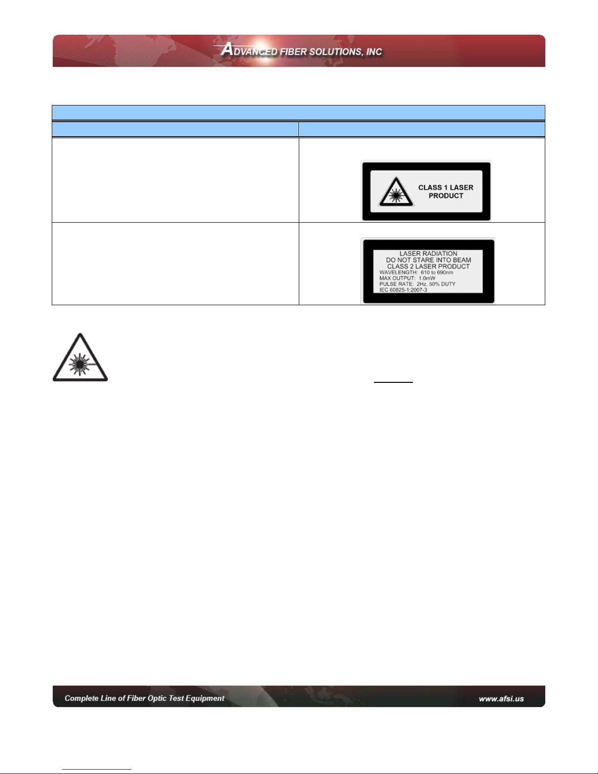
Safety Information
roduct Offering Laser Class
•AF-DR-515 (850nm/1300nm)
•AF-DR-525 (1310/1550nm)
•AF-DR-529 (1310/1550/1625nm)
•AF-DR-535 (850/1300/1310/1550nm)
Class 1 laser output
•VFL ort
Class II laser output – Do not stare at beam
Warning! When working with an O DR, Never look or stare directly
into the optical outputs of fiber optic test equipment, patch cords or test jumpers.
Use of procedures or adjustments other than those specified herein may result in
hazardous radiation exposure. Optical radiation that is harmful to the eye may be
present. his may result in permanent eye damage. While the chances of such an
occurrence taking place is very unlikely, Advanced Fiber Solutions, Inc. still
strongly advises against this. Refer to your company’s safety procedures when
working with optical systems.
he DR-500 series Handheld O DR contains no user serviceable parts. Except for
cleaning the optical port, this instrument must be returned to Advanced Fiber
Solutions, Inc. or an authorized agent for repair or calibration.
he unit corresponds to GOS 12.2.091 (IEC 61010-1), equipment class III. he
AC/DC adaptor corresponds to GOS 12.2.091 (IEC 61010-1), equipment class II.

© 2010 Advanced Fiber Solutions, Inc. All rights reserved – V-05
19 Norfolk Ave * Easton * MA * USA * 02375 - Phone: 508.238.7100 * Fax: 617.507.0784 6
Introduction
hank You for purchasing Advanced Fiber Solutions, Inc. Optical ime Domain
Reflectometer. he purpose of this User Guide is to explain how to use and
maintain this O DR. If you have any questions regarding your fiber optic
instrument or if you need technical or application support, please contact
Advanced Fiber Solutions, Inc. his manual includes the technical characteristics,
operating principles and operating procedures for the DR-500 Series Handheld
O DR.
DR-500 Series ackage Includes
•DR-500 Series Handheld OTDR device
•AC/DC adapter
•Interface cable USB A – mini USB B
•Storage Battery
•OTDR C Application Software CD
•User Guide for OTDR and C application
software
•Carrying Case
Recommended Accessories
Fiber optic test cables (launch cables, pulse suppression cables, patch cords or
jumpers) to connect the fiber under test and the O DR. he test cables must have
the same core and cladding size as the fiber under test.
A supply of optical cleaning pads, isopropyl alcohol or filtered compressed air is
recommended for cleaning the fiber optic connectors.
Important! Proper care in handling should be taken when using any precision
optical test equipment. Scratched or contaminated optical connectors can impact
the performance of the instrument. It is important to keep the optical ports
covered when the unit is not being used.

© 2010 Advanced Fiber Solutions, Inc. All rights reserved – V-05
19 Norfolk Ave * Easton * MA * USA * 02375 - Phone: 508.238.7100 * Fax: 617.507.0784 7
Unit Introduction
he unit is one of the most compact O DR’s on the market today, idea for
handheld use and pocket transportation. he unit is light weight weighing less
than 1.6 Lbs. It is extremely rugged with a thick protective rubber boot
surrounding the outer case. It also offers a long battery life enabling the technician
to continuing test up to eight hours.
It is a full featured O DR offering four different performance classes to choose
from, with a dynamic range starting at 23dB going up to 43dB. Class A is
optimized for private and premise networks. Class B is optimized for F x and
CA V networks. Class C is optimized for close event detection and large
attenuation measurements like PONS networks. Class D is optimized for long haul
applications.
Along with a wide dynamic range to choose from, the unit offers a number of
wavelength options for both single mode and multimode applications with single,
dual, tri and quad models available. Wavelength options include 850nm, 1300nm,
1310nm, 1550nm and 1625nm.
he unit is simple to operate and is the perfect installation, maintenance and link
trouble shooting tool. It is the ideal O DR for either the inexperienced or the
experienced technician. he unit supports both a manual mode for the expert user
which enables parameter setup and an automatic mode for the less experienced
user which allows one touch auto run testing. he unit utilizes active sync for
seamless USB connectivity with desktop software for advanced data analysis and
storage capabilities.
It is fully compliant and compatible with the .sor file format outlined in the belcore
GR-196 O DR data standardization document. Other optional features offered by
this industry leading O DR include a built in power meter, light source and Visual
Fault Locator.
Product Highlights and Key Features
•Compact and rugged case •Bellcore .sor format compatible
•Single, dual, tri and quad λ
models available •USB jump drive compatible for extra storage
•Events table and auto test
function •9 hours of operation, fast charging Li-Ion battery
•Up to 43dB Dynamic Range •High contrast full color display
•Weight less than 1.6 lbs •User friendly and easy too operate
•Four performance classes to
choose from •Optional features: ower Meter and Light Source

© 2010 Advanced Fiber Solutions, Inc. All rights reserved – V-05
19 Norfolk Ave * Easton * MA * USA * 02375 - Phone: 508.238.7100 * Fax: 617.507.0784 8
Working Principle
he O DR’s operating principle is based on the measurement of the Raleigh
Backscattering Signal, generated by sending a high power optical pulse from the
O DR through the optical fiber. Light is reflected back to the O DR. his
backscattered light is measured by the sensitive optic receiver, converted to digital
form and averaged to improve the signal to noise ratio. he resulting signal forms
a graph called a TRACE. he trace is a visual representation of the backscattering
coefficient created by the O DR to determine the “events.” he trace shows the
“events” on the fiber optic link such as breaks, splice loss, bends, attenuation and
distance.
OTDR Distance Calculation Formula
Distance = c * t / ( 2 * n )
c = speed of light in a vacuum
n = index of refraction of the fiber under test
Time delay between pulse emitted

© 2010 Advanced Fiber Solutions, Inc. All rights reserved – V-05
19 Norfolk Ave * Easton * MA * USA * 02375 - Phone: 508.238.7100 * Fax: 617.507.0784 9
Technical Specifications
Class Definitions**
Class Definitions Ax A A+ B C D D+
Dynamic Range
Single mode
1310/1550/1625nm
25/27dB
@20uS
31/29/2
dB
@20uS
34/32/31
dB
@20uS
39/37/36
dB
@20uS
37/35/34
dB
@20uS
42/40/39
dB
@20uS
44/42/41dB
@20uS
Dynamic Range
Multimode
50/1300nm
N/A 23/24dB N/A N/A 26/2 dB N/A N/A
Event Dead Zone
Both MM & SM 2.5 M 2.5 M 1. M 1. M 1.0 M 1.4 M 1.4 M
Attenuation Dead
Zone
Both MM & SM
12 M 9.5 M 6.5 M 6.5 M 4.5 M 9.0 M 9.0 M
All Units
Distance Range 2,5,10,20,40, 0,120,160,240 Km
Data Points Up to 64,000
Loss Resolution 0.001dB
Distance Accuracy ±(0.5+5´10-5´L+(n/n)´L)
Refractive Index Range 1.0000…..2.0000
Language English
OTDR Modes Full Auto, Expert and Real Time
Attenuation Measurement Accuracy 0.05dB
Sampling Resolution 0.16m…..7.6m
Storage Capability ~ 500 traces
Unit Measurement Meter
Temperature Specifications
Operation Temperature 0°.. +40°C
Relative Humidity 95% Without Condensation
© 2010 Advanced Fiber Solutions, Inc. All rights reserved – V-05
19 Norfolk Ave * Easton * MA * USA * 02375 - Phone: 508.238.7100 * Fax: 617.507.0784 10
GETTING STARTE
Preparation for work
he device maybe operated when powered by the external 12V AC/DC adapter or
separately by the internal battery, once the battery is charged to an acceptable
operational level. If the unit is being charged by the external 12V power supply
both the green “BA ERY” LED and the orange “CHARGE” LED on the face panel
will illuminate. he fiber to be tested is connected to the O DR’s optical connector
on the front panel of the unit. It is recommended to always use a launch cable
when using an O DR but it is not necessary. If testing the cable directly with the
O DR the cable connector style must match the O DR output connector. Power
Meter optical port offers versatility with removable connector adapters. All O DR
connector ports and test cables should be kept clean and free of dust and dirt for
optimal unit operation.
Powering On/Off unit
he unit is powered On or Off by pressing and holding the button for several
seconds.
When the unit is powered on the green LED on the face panel will illuminate.
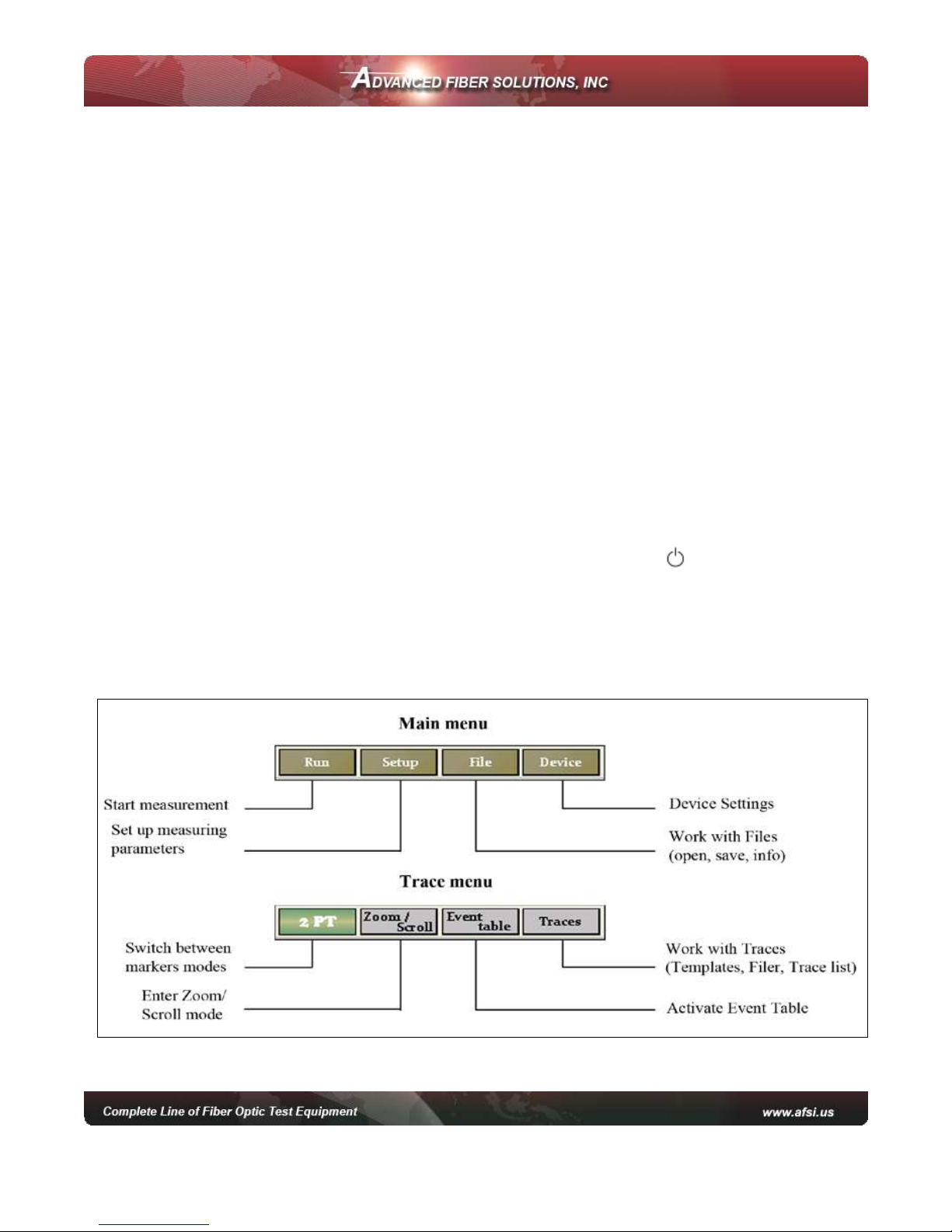
Menu Options
© 2010 Advanced Fiber Solutions, Inc. All rights reserved – V-05
19 Norfolk Ave * Easton * MA * USA * 02375 - Phone: 508.238.7100 * Fax: 617.507.0784 11
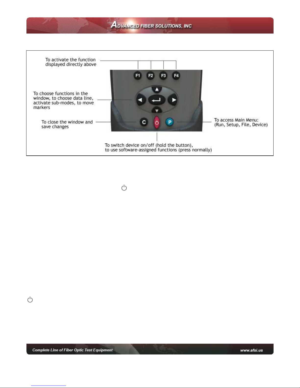
Keypad Options
Parent Buttons P, C and
P Button
enables the technician to switch
between currently activated menu to
Main menu.
C Button
by default is an ESC key (escape or back) but it can also be used for
the following
•Stop a measurement when running.
•Reset to Main menu.
•Exit from dialog boxes and modes (for instance the Events table mode).
•Un-zoom/Reset zoom state of trace.
button
as well being the key to turn the unit On and Off also has a software
assigned function and will show/hide a trace preview box in the right top area of
the screen when pressed.
© 2010 Advanced Fiber Solutions, Inc. All rights reserved – V-05
19 Norfolk Ave * Easton * MA * USA * 02375 - Phone: 508.238.7100 * Fax: 617.507.0784 12
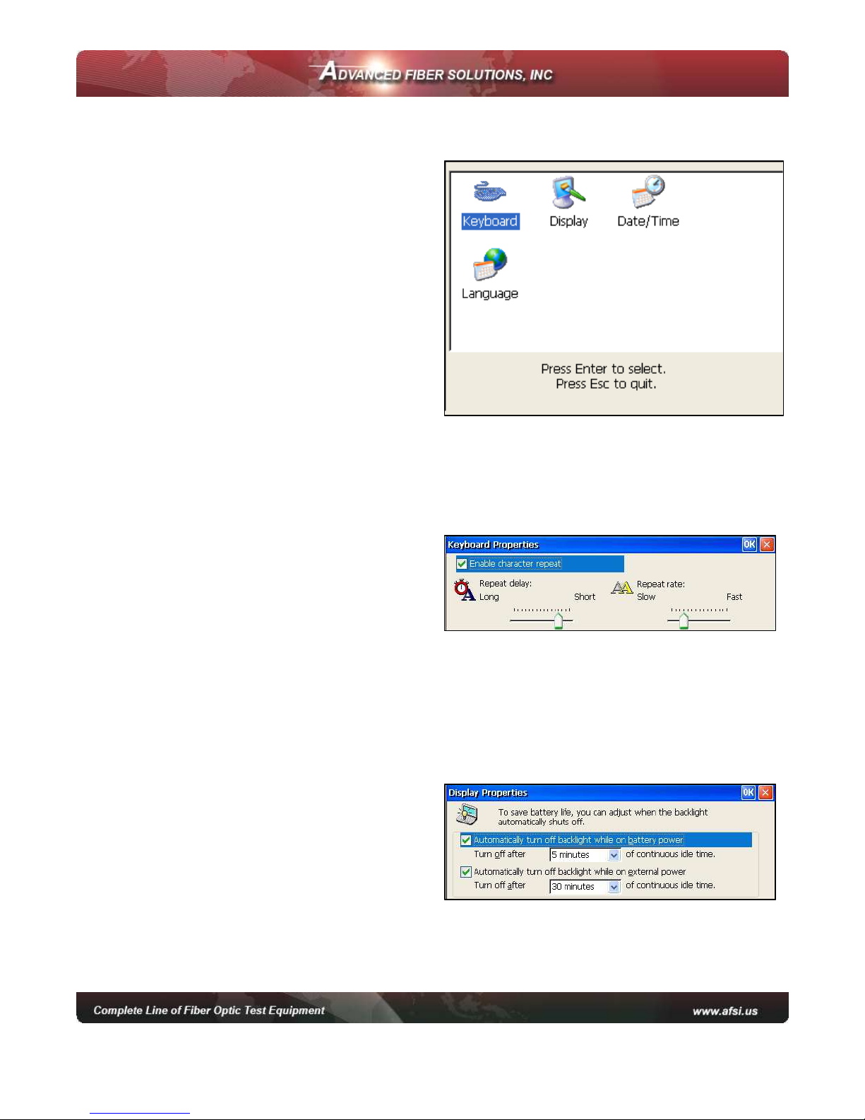
Customizing your OT R
he following features can be customized
on the DR-500 series unit.
•Keyboard
•Display
•Date/ ime
o customize the device.
•Press to access the Main menu.
•Press F4 (Device) to enter device
mode.
•Press F1 (System Setup) to
activate the setup window.
•Use the left/right arrow to choose
the desired icon in the window.
Keyboard Properties
•Select the Keyboard icon and open
the keyboard properties window.
•Use the up/down arrows to move
between the lines.
•Use left/right arrows to change the values.
•ick the “Enable character repeat” check box to enable a continuous repeated
action when the desired button is continuously pressed.
•Press C to close the window and save the changes.
isplay Properties
•Select the Display icon and open
the Display properties window
•Use the up/down arrows to move
between selections.
•Press Enter to enable any checkbox or show the list of values.
•Press C to close the window and save changes.

© 2010 Advanced Fiber Solutions, Inc. All rights reserved – V-05
19 Norfolk Ave * Easton * MA * USA * 02375 - Phone: 508.238.7100 * Fax: 617.507.0784 13
Setting ate and Time
Note: When a trace is saved the device also
saves the corresponding time and date
•Select the Date/ ime icon and open the
Date/ ime properties window.
•Use the left/right arrows to move to the
next selection to be changed.
•Use the up/down arrows to change values.
•Press the to move to between selection
options.
•Press the C to close the window and save the changes.
Setting Language
•
Select the Language icon and open the
Language properties window.
•
Use up/down arrows to select the desired
language.
•
Press C to close the window and save the
changes.
© 2010 Advanced Fiber Solutions, Inc. All rights reserved – V-05
19 Norfolk Ave * Easton * MA * USA * 02375 - Phone: 508.238.7100 * Fax: 617.507.0784 14
Working with the OT R
Setting up Measuring Parameters
•Press to access the main menu.
•Press F2 (Setup) to access the measuring
parameters window.
•o move to desired parameter selection
use the up/down or left/right arrows.
•Press Enter to activate the desired
parameter selection.
•Use the up/down arrows to choose the
desired value. he value will become
highlight.
•Press Enter to confirm changes.
•Press C to close the window and save the changes.
Note:
1Several wavelengths can be selected simultaneously. In this case measurements will
be performed on all chosen wavelengths one after another without stopping.
2If an DR-5 Series is the quad OTDR model(for both Single mode and Multimode
applications) the choice of single-mode OTDR wavelength (SM131 , SM 155 etc) will
automatically cancel out the choice of multimode OTDR wavelengths (MM 85 ,
MM13 ) and vice versa.

© 2010 Advanced Fiber Solutions, Inc. All rights reserved – V-05
19 Norfolk Ave * Easton * MA * USA * 02375 - Phone: 508.238.7100 * Fax: 617.507.0784 15
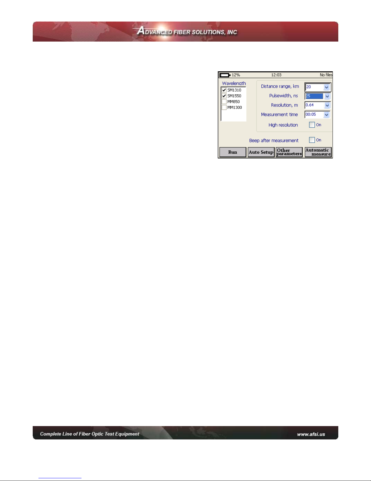
Parameters
•Wavelength - For Multimode 850nm or 1300nm and for single mode
1310nm, 1550nm or 1625nm.
•
Distance Range, Km
-
he maximum value of the measured distance. he
value of the distance range should exceed the length of the line under test
by more than 20%.
•ulsewidth, ns – his determines the value of the optical pulse duration.
he range of the acceptable optical pulse value is dependent on the chosen
Distance Range and is automatically limited by the O DR program.
•Resolution, m – his determines the distance between two samples
(sampling intervals) of the trace. he value is dependent on the Distance
Range.
•Measurement Time, Min/Sec – his determines the duration of the
measurement process with averaging. Live mode performs fiber monitoring
in real time mode.
•High Resolution - In this mode the optical receiver bandwidth is increased.
Best used when testing a short cables and requiring excellent dead zone – do not use on
long fiber lengths than require high dynamic range.
Note: To have the unit Auto Select the parameters press Auto Setup. The program
will perform a short measurement on the connected fiber and automatically define the
optimal parameters for that fiber. The technician can then modify the parameters
manually if desired and run a measurement

© 2010 Advanced Fiber Solutions, Inc. All rights reserved – V-05
19 Norfolk Ave * Easton * MA * USA * 02375 - Phone: 508.238.7100 * Fax: 617.507.0784 16
Additional Measuring and Analysis Parameters
•Press to access the Main menu.
•Press F2 (Setup).
•Press F3 (Other Parameters) to activate the additional measuring
parameters window.
oSet Refractive Index for each O DR wavelength.
oSet Backscattering Coefficient for each O DR wavelength.
oSet automatic Analysis Threshold parameters.
•Move to the desired parameter selection using the left/right arrows. Press
Enter to activate the selection.
•Use the up/down arrows to choose the desired setting. Once highlighted
press Enter to confirm and change.
•Press C to close and save changes.
Additional Parameters
•Backscattering Coefficient, BC – represents the level of backscattering in
a particular fiber. It is used for Reflectance and ORL measurement and can
be obtained from the fiber manufacturer. his parameter value can be stored
for any saved trace.
•Refractive Index – (also known as group index) is used to convert time to
distance. For precise distance measurement it is important that this value is
accurate and can be obtained from the fiber manufacturer. his parameter
value can be stored for any saved trace.
•Automatic race Analysis Threshold – have the following selectable
features
oSplice Loss, LT – threshold of the event attenuation value in dB.
Events with attenuation value that exceeds the threshold value will be
shown in the Events Table.
oReflectance, RT – threshold of the event reflectance value in dB. he
reflected event having a reflectance higher than the threshold value
are shown in the Events Table.
oEnd-of-Fiber, ET – threshold of the event attenuation value in dB for
defining the fiber end. he first event with an attenuation exceeding
the threshold value is defined during the automatic trace analysis as
an optical fiber end. All subsequent events will be ignored.
oAttenuation, CT – Attenuation coefficient threshold value of the
section in dB/km. Exceeding the attenuation coefficient threshold value
will mark the section with an * in the Event Table.
© 2010 Advanced Fiber Solutions, Inc. All rights reserved – V-05
19 Norfolk Ave * Easton * MA * USA * 02375 - Phone: 508.238.7100 * Fax: 617.507.0784 17
Trace View Parameters
•Zoom coefficient selection – x1.1, x1.3, x2, x5 or x10.
•Inverts color in trace window – changes the trace color for different
lighting environments.
•Show grid scale values – Displays grid lines value.
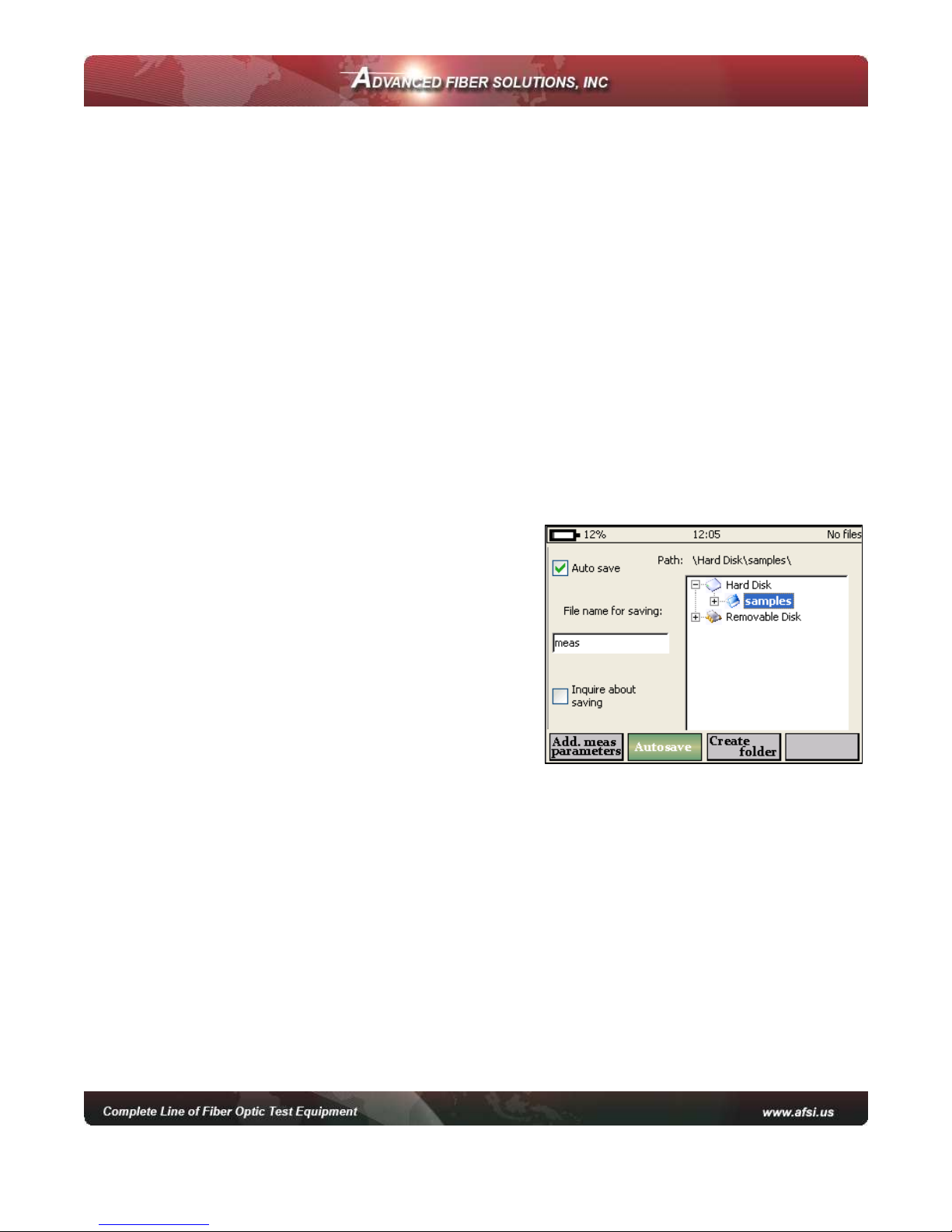
Automatic Saving
he program enables the automatic saving of measured traces into the DR-500
Series memory immediately after a measurement completion. It is advisable to
use Auto-Saving option when measuring a large number of traces (like cable
cores) to collect data for post testing analysis.
Warning! To avoid unwanted file saving and flash memory overflow, Autosave option is
disabled when device is turned on.
•Press to access Main menu.
•Press F2 (Setup) and enter parameters
field.
•Press F3 (Other Parameters).
•Press F2 (Autosave) to activate the
Autosave setup window.
oPress Enter to select or de-select
the Auto save check box.
oUse the up/down arrows to
choose the desired field. he field
will become highlight, press Enter
to activate it and change the value.
oChange the name of the template for auto saving in the “File name for
saving” field.
oo have the O DR ask if a file should be saved upon competition of a
measurement select the “Inquire about saving” check box.
ohe file path window allows the user to change the Auto save file
location.
oPress F3 (create folder) to create a new folder for the Auto save
location.
oPress C to quit the Auto save window and save settings.
© 2010 Advanced Fiber Solutions, Inc. All rights reserved – V-05
19 Norfolk Ave * Easton * MA * USA * 02375 - Phone: 508.238.7100 * Fax: 617.507.0784 18
Start Measurement
•Press to access the Main menu.
•Press F1 (Run) when in the Main menu or F1 (Run) when in the Measuring
Parameters field to run a measurement. he measurement will operate
according to the values set in the Measuring arameters window.
•he green bar at the bottom part of the screen will indicate the time past for
the current measurement.
•he green “Laser” LED on the face panel will be illuminated during a
measurement.
•Press C to stop a measurement manually.
Working with Files
All traces are saved in memory in the BELLCORE version 2.0 format and have a
.sor file extension
DR-500 Series files can be opened in other O DR software programs if the
program supports the .sor file format. If several wavelengths are measured
simultaneously all the traces are saved as a group. hey will have the same
common part of the name with the wavelength value added to the name –
example afs_1310, afs_1550 e.t.c.
Opening Trace Files
he device can open up to four traces at a time –
an active trace and additional traces.
To open file
•Press to access the Main menu.
•Press F3 (File) to enter the File window.
•Use the up/down arrows to navigate
through the file list.
•Use right arrow to open folders.
•Highlight the required file.
•Press F2 (Open) to open the file.
•o open additional traces see “Select races to Compare”.
Note: If the measurement was performed on several wavelengths the user will be asked
to open all corresponding files.

© 2010 Advanced Fiber Solutions, Inc. All rights reserved – V-05
19 Norfolk Ave * Easton * MA * USA * 02375 - Phone: 508.238.7100 * Fax: 617.507.0784 19
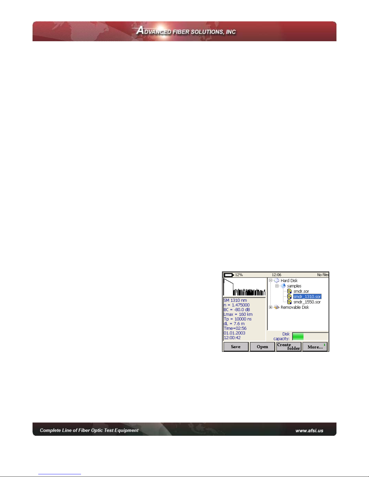
Saving Trace Files
•Press to access Main Menu.
•Press F3 (File) to enter File window.
•Use the up/down arrows to navigate through
the file list.
•If required press F3 (Create Folder) to create a
new folder.
•Highlight the required file or folder to save it
and press F1 (Save) – the File name dialog box
will be opened.
•Note: the file can be saved in .sor format or .pdf format.
•Use arrows to enter the desired name for the trace.
•Press F2 (Left) and F3 (Right) to navigate through the name.
•Press F1 (Delete) to delete any letter.
•Press C to save the trace or F4 (Cancel) to return to the File window without
saving.
Note: Highlighting the file will tell the program to use its name and location as a template
for a new trace.
Additional functions
o access additional functions press F4 (More). his menu enables the technician
to copy or delete the highlighted trace. It also allows access to the information
table of the highlighted trace.
To access the information window
•Activate additional function window.
•Use the up/down arrows to select and highlight a trace.
•Press F1 (Information) to activate the information window.
Note: Data in the information window can not be modified.
To delete files
•Activate additional function window.
•Use the up/down arrows to select and
highlight a trace.
•Press F2 (Delete) to remove the selected file
from the memory of the device.
•Confirm the deleting process.

© 2010 Advanced Fiber Solutions, Inc. All rights reserved – V-05
19 Norfolk Ave * Easton * MA * USA * 02375 - Phone: 508.238.7100 * Fax: 617.507.0784 20
To Copy and Paste
•Activate additional function window.
•Use the up/down arrows to select and highlight a trace.
•Press F3 (Copy) to copy the selected file/trace from memory.
•Use the up/down and left/right arrows to select a location to copy to.
•Press F3 (Paste) to paste a file to the selected location.
To Open a File
•Activate File window.
•Use the up/down arrows to highlight a
file/trace.
•Press F2 (Open) to open the selected trace.
This manual suits for next models
3
Table of contents


