Advanced Lighting Systems LiveLED 100 User manual
ALS-LLED-100
Model NuMber
InstallatIon InstRUCtIons
livelED 100

1.0 Important Safety Instructions ………….......…………..
2.0 Placement & Mounting Requirements ...........………...
3.0 General Operating Instructions.................................…
4.0 Preset Program Table …….…….........…….............….
5.0 DMX Control...............................................................
6.0 Quick Settings………..………......................................
7.0 Resetting DMX Programs..............................................
8.0 Troubleshooting…………...................................….….
9.0 Maintenance of Luminaire...............................................
3
3
3
5
6
7
8
9
9
Page
Table of Contents
Thank you for purchasing the LiveLED™ 100 from Advanced Lighting Systems, Inc. This LED porta-
ble luminaire has been engineered and designed to be simple to operate, energy efficient and reliable.
The LiveLED 100 is designed for architectural, entertainment and other applications where white and
color light washing is required. The LiveLED 100 is a digital, full spectrum capable source comprised
of 39.6 watts of Blue LEDs, 39.6 watts of Green LEDs, and 22 watts of Red LEDs. The LiveLED 100
features an integrated power supply and a DMX control panel with XLR in and out connectors.
This manual is intended to provide basic information for the use, installation, operation
and maintenance of the LiveLED 100.

3
Ad v A n c e d Li g h t i n g Sy S t e m S , L L c •519 Li n c o L n Ro A d •SA u k ce n t R e , mi n n e S o t A 56378 •t320 352 0088 •f320 352 0089 •A d v A n c e d L i g h t i n g .c o m •n A S d A q : n e x S
1.0 IMPORTANT SAFETY INSTRUCTIONS
2.0 Placement & Mounting Requirements
The LiveLED 100, is designed to operate in an indoor or outdoor environment. The proper voltage
required at the site is 110 - 240 VAC, 60/50 Hz. The unit draws 1 Amp at 120 volts. The LiveLED
100 is yoke mounted and is designed for operation in any orientation allowed by the yoke. The
LiveLED 100 must be adequately ventilated. Recommended operating temperatures are from -30
degrees F (-35 degrees C) to 140 degrees F (60 degrees C). The illuminator should be placed with
6-8” inches clearance on the sides and 12” inches of back clearance if unit is placed in front of an-
other unit. When more than one LiveLED is installed in the same location, provide each unit with the
same minimum clearances as noted above. Proper ventilation is absolutely necessary to maintain
LED life.
SAVE THESE INSTRUCTIONS.•
WARNING: RISK OF INJURY.•
WARNING: THE HEAT SYNC COMPONENT OF THIS UNIT MAY BECOME HOT DURING•
OPERATION. TAKE CAUTION WHEN HANDLING UNIT DURING OPERATION.
WARNING: RISK OF ELECTRIC SHOCK.•
CAUTION: CONNECT ONLY TO A CIRCUIT PROTECTED BY A CLASS A GROUND FAULT•
CIRCUIT INTERRUPTER
DO NOT BURY POWER CORD•
READ & FOLLOW ALL INSTRUCTIONS
3.0 General Operating Instructions
With the unit properly installed, plug the illuminator power inlet cable into a suitable AC power
source. The LED modules will immediately light. The DMX color control system will cycle and then
stop on specific colors relative to whatever control settings the unit is currently set to. Unless oth-
erwise specified, units are shipped with color controls not preset. Color control setup is required to
achieve desired colors and effects. All color and effects control is activated using the 3 rotary knobs
on the unit (see control panel picture). The unit may operated as a stand alone single unit, in master/
slave configuration with other units or remotely using USITT DMX 512 control protocol generated by
an external unit. Consult the instructions for the DMX controller or other signal processor that will be
used for programming instructions. The DMX signal can be delivered through either of the XLR con-
nectors located on the bottom left of the illuminator (see control panel picture). The remaining con-
nector can be used as an output signal (in the case of a daisy chain) or left un-used (terminated).
4
Ad v A n c e d Li g h t i n g Sy S t e m S , L L c •519 Li n c o L n Ro A d •SA u k ce n t R e , mi n n e S o t A 56378 •t320 352 0088 •f320 352 0089 •A d v A n c e d L i g h t i n g .c o m •n A S d A q : n e x S
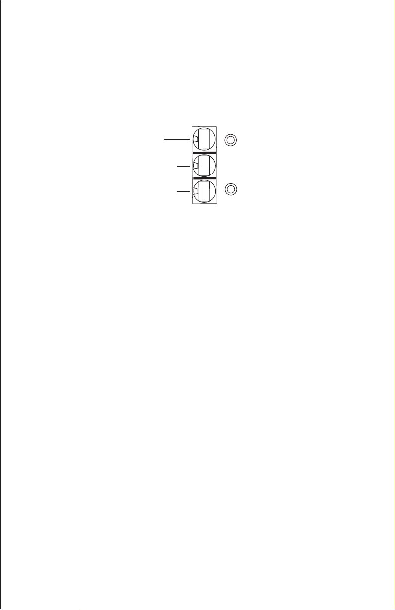
3.0 General Operating Instructions
Top knob is 3rd digit
Middle knob is 2nd digit
Bottom knob is 1st digit
Green
Red
DMX Rotary Control
Knobs correspond to
DMX code as follows:
CONTROL PANEL
Red LED light indicates DMX system has power.
Green indicates DMX system has signal.
Flashing Green indicates DMX operation is being executed
STAND ALONE OPERATION
To operate the LiveLED 100 as a stand alone unit, rotate the knobs on the Control Panel to activate
the preset program desired (see preset program table below).
MASTER/SLAVE OPERATION
The master / slave control allows multiple units to operate in synchronization without an external con-
troller. Using 3 pin XLR cables, link the units together to the XLR cables on the rear of each LiveLED.
Either connector may be used as either the in or out. Choose a unit to be the Master. Set the rotary
knobs of the Master to the desired preset program (see preset program table below). Set all other
Slave units to 001. Be sure none of the units are connected to any other controller or DMX system.
When the system power is turned on, all Slave units will follow the Master. Check the green indicator
light on the control panel of the Slave units to insure that units are receiving a DMX signal from the
Master unit.
Note: The rotary knob next to the red indicator light is the first digit for the preset programs (see
control panel picture).
x1
x10
x100

5
Ad v A n c e d Li g h t i n g Sy S t e m S , L L c •519 Li n c o L n Ro A d •SA u k ce n t R e , mi n n e S o t A 56378 •t320 352 0088 •f320 352 0089 •A d v A n c e d L i g h t i n g .c o m •n A S d A q : n e x S
4.0 Preset Program Table
601 RED
602 BLUE
603 GREEN
604 MAGENTA
605 YELLOW
606 CYAN
607 WARM WHITE
608 COOL WHITE
609 BLUE MAGENTA
610 RED MAGENTA
611 TURQUOISE
612 ORANGE
613 LIGHT BLUE strobe
614 LIGHT YELLOW
615 LIGHT WARM PINK
616 LIGHT GREEN
617 LIGHT SALMON
618 LIGHT AMBER
619 LIGHT LAVENDER
STATIC COLORS:
650 Red strobe 0.5 second strobe
651 Red strobe 0.25 second strobe
652 Red strobe 0.1 second
660 Blue strobe 0.5 second strobe
661 Blue strobe 0.25 second strobe
662 Blue strobe 0.1 second strobe
670 Green strobe 0.5 second strobe
671 Green strobe 0.25 second strobe
672 Green strobe 0.1 second strobe
680 Cool White 0.5 second strobe
681 Cool White 0.25 second strobe
682 Cool White 0.1 second strobe
COLOR STROBE:
(flash on/off & pause for time indicated)
640 8 Color snap change w/10 second pause
641 8 Color snap change w/5 second pause
642 8 Color snap change w/2 second pause
643 8 Color snap change w/1 second pause
644 8 Color snap change w/0.5 second pause
645 8 Color snap change w/0.25 second pause
COLOR SNAP CHANGE:
(white/salmon/red/blue/green/magenta/yellow/cyan)
620 Red/Blue/Green 30 second cross fade
621 Red/Blue/Green 20 second cross fade
622 Red/Blue/Green 15 second cross fade
623 Red/Blue/Green 10 second cross fade
624 Red/Blue/Green 5 second cross fade
625 Red/Blue/Green 1 second cross fade
630 Red/Magenta/Yellow 30 second cross fade
631 Red/Magenta/Yellow 20 second cross fade
632 Red/Magenta/Yellow 15 second cross fade
633 Red/Magenta/Yellow 10 second cross fade
634 Red/Magenta/Yellow 5 second cross fade
635 Red/Magenta/Yellow 1 second cross fade
COLOR FADES:

6
Ad v A n c e d Li g h t i n g Sy S t e m S , L L c •519 Li n c o L n Ro A d •SA u k ce n t R e , mi n n e S o t A 56378 •t320 352 0088 •f320 352 0089 •A d v A n c e d L i g h t i n g .c o m •n A S d A q : n e x S
5.0 DMX Control
If the unit is receiving a DMX signal, the green light on the control panel will illuminate.
Setting the Base DMX Address
As with all products that are DMX controlled, the LiveLED 100 requires that DMX channels be set
to specific “addresses” in order that the unit will respond to a control unit. Using the adjustment
knobs, set the desired DMX address on any address from 001 - 512.
The LiveLED 100 uses 5 DMX channels on a control board.
CHANNEL 1 - Red
CHANNEL 2 – Green
CHANNEL 3 – Blue
CHANNEL 4 – Preprogrammed effects
CHANNEL 5 – Preprogrammed effects

7
Ad v A n c e d Li g h t i n g Sy S t e m S , L L c •519 Li n c o L n Ro A d •SA u k ce n t R e , mi n n e S o t A 56378 •t320 352 0088 •f320 352 0089 •A d v A n c e d L i g h t i n g .c o m •n A S d A q : n e x S
6.0 Quick Settings of Preset Colors & Effects
1 Red 0 255
2 Green 0 255
3 Blue 0 255
4 No Action 0 10
4 Magenta 11 21
4 Yellow 22 32
4 Cyan 33 43
4 Warm White 44 54
4 Cool White 55 65
4 Blue Magenta 66 76
4 Red Magenta 77 87
4 Turquoise 88 98
4 Orange 99 109
4 Light Blue 110 120
4 Light Yellow 121 131
4 Light Warm Pink 132 142
4 Light Green 143 153
4 Light Salmon 154 164
4 Light Amber 165 175
4 Light Lavender 176 186
4 RGB: 30 Crossfade 187 197
4 RGB: 20 Crossfade 198 208
4 RGB: 15 Crossfade 209 219
4 RGB: 10 Crossfade 220 230
4 RGB: 05 Crossfade 231 241
4 RGB: 01 Crossfade 242 252
5 No Action 0 9
5 RMY: 30 Crossfade 10 19
5 RMY: 20 Crossfade 20 29
5 RMY: 15 Crossfade 30 39
5 RMY: 10 Crossfade 40 49
5 RMY: 05 Crossfade 50 59
5 RMY: 01 Crossfade 60 69
Channel: Color Crossfades: DMX Value (Min): DMX Value (Max):
5 8 Color: 10 Snap 70 79
5 8 Color: 05 Snap 80 89
5 8 Color: 02 Snap 90 99
5 8 Color: 01 Snap 100 109
5 8 Color: 0.5 Snap 110 119
5 8 Color: 0.25 Snap 120 129
Snap To Color (White/Salmon/Red/Blue/Green/Magenta/Yellow/Cyan)
5 8 Color: 10 Snap 70 79
5 8 Color: 05 Snap 80 89
5 8 Color: 02 Snap 90 99
5 8 Color: 01 Snap 100 109
5 8 Color: 0.5 Snap 110 119
5 8 Color: 0.25 Snap 120 129
Snap To Color (White/Salmon/Red/Blue/Green/Magenta/Yellow/Cyan)

8
Ad v A n c e d Li g h t i n g Sy S t e m S , L L c •519 Li n c o L n Ro A d •SA u k ce n t R e , mi n n e S o t A 56378 •t320 352 0088 •f320 352 0089 •A d v A n c e d L i g h t i n g .c o m •n A S d A q : n e x S
Strobe: (Flash on/off & pause for time indicated)
5 Red Strobe: 0.5 130 139
5 Red Strobe: 0.25 140 149
5 Red Strobe: 0.1 150 159
5 Blue Strobe: 0.5 160 169
5 Blue Strobe: 0.25 170 179
5 Blue Strobe: 0.1 180 189
5 Green Strobe: 0.5 190 199
5 Green Strobe: 0.25 200 209
5 Green Strobe: 0.1 210 219
5 Cool White Strobe: 0.5 220 229
5 Cool White Strobe: 0.25 230 239
5 Cool White Strobe: 0.1 240 249
6.0 Quick Settings of Preset Colors & Effects (Cont.)
The DMX program allows a DMX controller to have complete control of color and effects. For
custom cues, the programmer may use channels 1 through 5.
If DMX controlled pre-programmed sequences is required, the programmer should use a cue loop
to send regular updates of the DMX values to the other unit(s). This will insure that all addressed
SAVI™ Flare luminaires remain in sync with each other.
7.0 Resetting the DMX Programs:
Set the adjustment knob to a value of: 000 and disconnect the power (or turn the fixtures off). The
fixtures will then reset themselves.

9
Ad v A n c e d Li g h t i n g Sy S t e m S , L L c •519 Li n c o L n Ro A d •SA u k ce n t R e , mi n n e S o t A 56378 •t320 352 0088 •f320 352 0089 •A d v A n c e d L i g h t i n g .c o m •n A S d A q : n e x S
Symptom: Probable Cause: Suggested Remedy:
Unit does not light No power to unit Check power supply & cord
Line voltage is <90 VAC Use @ rated voltage
Power supply failure Contact Authorized Distributor
Driver failure Contact Authorized Distributor
One color won’t light Damaged driver Contact Authorized Distributor
LED board short Contact Authorized Distributor
Low performance Dirty Lens Clean lens w/ soft dry cloth
Damaged lens Contact Authorized Distributor
Damaged sub-optic board Contact Authorized Distributor
No DMX response Bad cable connection Check cables
DMX driver malfunction Contact Authorized Distributor
Address issues Check for proper DMX address
9.0 Maintenance of Luminaire
8.0 Troubleshooting
Prior to any maintenance or service of the unit, always disconnect power cord and allow unit to
cool for at least five (5) minutes.
Periodic Cleaning:
Clean the LiveLED at least once every 6 months. Dust exterior with a soft cloth. Make certain that
lenses are free of obstructions and debris.
Fuse Replacement
In the event that the fuses need to be replaced, use only 250 volt 5 amp AC type of fuse. Turn the
power OFF; remove the power cord from the power outlet. Locate the fuse holder on the rear of
the fixture. Remove and replace the fuses if needed. Plug in the power cord and the unit is ready
for continued operation.
©2008 Nexxus Lighting, Inc.
For additional assistance or questions contact an authorized distributor or dealer for
Advanced Lighting Systems, Inc. or contact the factory at:
Advanced Lighting Systems, Inc.
519 Lincoln Road
Sauk Centre, MN 56378
Tel: 320.352.0088
Fax: 320.352.0089
©2008 Nexxus Lighting, Inc.
LIMITED WARRANTY
Nexxus Lighting, Inc. warranties its products, excluding lamps, to be free from defects in material and/
or workmanship, under normal condition, use and service, for a period of two (2) years from the original
invoice date (Five (5) Years for Red, Amber and Orange FlexLED and Border Light LED products and one
(1) Year for Non-UL Listed Power Supplies). If proof of purchase is provided, Nexxus Lighting will war-
ranty the product for two (2) years from date of the purchase (Five (5) Years for Red, Amber and Orange
FlexLED and Border Light products and one (1) Year for Non-UL Listed Power Supplies).
TERMS AND CONDITIONS:
This warranty only applies when Nexxus Lighting products are properly wired and installed together as
a system; and operated within the electrical values shown on the Nexxus Lighting specification sheets;
used in lighting equipment designed and approved for the application and environmental conditions
(temperature, humidity) within the normal specified operating range of the system. This warranty does
not apply to any abnormal use in violation of any applicable standard, code or instructions for use in
installations including those contained in the latest National Electrical Code (NEC), the Standards for
Safety of Underwriters Laboratory, Inc. (UL), Standards for the American National Standards Institute
(ANSI), in Canada, the Canadian Standards Association (CSA), Europe (CE), Australia (C-Tick). This war-
ranty will not apply in the event of conditions demonstrating abnormal use or stress, including under/
over voltage conditions, excessive switching cycles, excessive operating hours, alterations, accident,
theft, misuse, abuse and damaged caused by negligent installation, improper maintenance or where
adequate care has not been taken to prevent damage to the lighting system. Replacement of Nexxus
Lighting components with any other manufacturer will void the entire warranty.
WARRANTY SERVICE CLAIMS:
Nexxus Lighting must issue a Return Material Authorization (RMA) number for all requests for warranty
review. To expedite service, please contact Nexxus Lighting Customer Representative: 407-857-9900.
If you are unsure whether a situation exists that is covered by this warranty, please contact Nexxus
Lighting Customer Service for assistance. In the event of a defect in material or workmanship during
the warranty period, Nexxus Lighting will repair or replace (at its own discretion) its products under the
conditions of the warranty.
RETURN OF DEFECTIVE PRODUCT:
After contacting Nexxus Lighting, Inc. and receiving the RMA#, the purchaser / user shall promptly re-
turn the product after receiving instructions regarding if, when and where to ship product. Product must
be returned within 30 days of receiving RMA#, Shipping box must be clearly marked with RMA#. Failure
to follow this procedure shall void this warranty. Nexxus Lighting will cover expenses for material but will
not cover shipping costs. Products returned without an RMA#will be refused and returned to sender at
the senders expense.
REPLACEMENT OF PRODUCT, LIMITS OF LIABILITY:
The foregoing shall constitute the exclusive remedy of the purchaser and the sole liability of Nexxus
Lighting, Inc. regarding its products and component warranty. NO WARRANTY OF MERCHANTABILITY
OR FITNESS FOR A PARTICULAR PURPOSE IS MADE OR IS TO BE IMPLIED. In no event shall Nexxus
Lighting, Inc. be liable for any other costs or damages including labor charges, lost profits or revenues,
incidental, special or consequential damages. Total liability shall not exceed the total extended purchase
price for the product. Nexxus Lighting, Inc. reserves the right to examine all failed Nexxus Lighting, Inc.
products and components to determine the cause of failure and patterns of usage and reserves the right
to be the sole judge as to whether any product or component is defective and covered under this
warranty.
MAN.ALS.LL100.V1.00
This manual suits for next models
1
Table of contents
Popular Lighting Equipment manuals by other brands

Revolution Micro
Revolution Micro Avici V owner's manual

Bosch
Bosch MIC7000 Quick installation guide

Conrad
Conrad 2612330 operating instructions

ML Accessories
ML Accessories RW6WW Installation & maintenance manual

MJ LED LIGHTNING
MJ LED LIGHTNING MJ-3001B-6IN1 user manual

Chauvet
Chauvet Cirrus user manual


