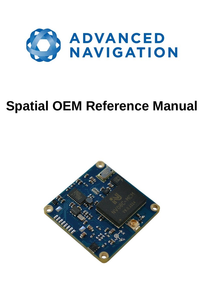
Advanced Navigation Spatial OEM User manual

Spatial OEM Development Kit
Manual

Spatial OEM Development Kit Manual
Page 1 of 20
Version 3.0
Table of Contents
1 Revision History..........................................................................................................................2
2 Introduction..................................................................................................................................3
2.1 Kit Contents.........................................................................................................................3
3 Quick Start...................................................................................................................................
3.1 Troubleshooting...................................................................................................................
OEM Development Board Overview............................................................................................5
.1 Spatial OEM Module............................................................................................................6
.2 Serial UART to USB Converter............................................................................................6
.3 Dual RS232 Transceiver......................................................................................................6
. GPIO Header and Status LEDs...........................................................................................7
.5 RF Connection..................................................................................................................... 8
5 Configuration and Operation.......................................................................................................9
5.1 Configuration Switches........................................................................................................9
5.1.1 Primary Serial Port to USB.........................................................................................10
5.1.2 Primary Serial Port to RS232 1 and GPIO 3 & to RS232 2......................................10
5.1.3 Primary Serial Port and GPIO 3 & to GPIO Header at TTL levels............................10
5.2 Power source.....................................................................................................................11
6 Electrical.................................................................................................................................... 12
6.1 Schematics........................................................................................................................ 12
6.2 Bill of Materials.................................................................................................................. 15
7 Mechanical................................................................................................................................ 17
7.1 Mechanical Drawing...........................................................................................................17
7.2 Optional Enclosure.............................................................................................................17

Spatial OEM Development Kit Manual
Page 2 of 20
Version 3.0
1 Revision History
Version Date Changes
3.0 29/0 /2015 Updated for hardware v1.2
2.0 22/0 /2013 Updated for hardware v1.1
1.0 28/08/2012 Initial Release

Spatial OEM Development Kit Manual
Page 3 of 20
Version 3.0
Introduction
The Spatial OEM development kit allows developers to quickly test and integrate Spatial OEM into
prototypes and low quantity products. It provides the user with access to all of Spatial OEM's
interfaces with a number of convenient connection options.
.1 Kit Contents
The Spatial OEM Development Kit includes:
1. 1x Spatial OEM Module (pre installed)
2. 1x OEM Development Board
3. 1x GNSS Antenna
. 1x Mini USB to USB A cable
5. 1x U.FL to U.FL cable (pre installed)
Attention
The OEM development board is an electrostatic sensitive device and must be
handled with care. Precautions must be taken when operating the OEM
development board.

Spatial OEM Development Kit Manual
Page of 20
Version 3.0
3 Quick Start
The Spatial OEM development kit is ready to function straight out of the box using the USB
interface. It is recommended that users familiarise themselves with Spatial OEM through the
Spatial Manager software prior to starting their own integration.
1. If you are using Windows, install Java from http://www.java.com.
2. Download Spatial Manager from the Advanced Navigation website.
3. Open Spatial Manager by double clicking on it. If this does not work, right click and choose
open with → Java
. Screw the GNSS antenna onto the board connector finger tight and place the antenna in an
area with a view of the sky.
5. Plug one end of the USB cable into the development board and the other end into your
computer.
6. Click connect in Spatial Manager. If the connection indicator does not turn green,
disconnect and try selecting another serial port.
3.1 Troubleshooting
If the serial port does not show up when the OEM development board is plugged in, the system
may require drivers. These are available from http://www.ftdichip.com/Drivers/VCP.htm.

Spatial OEM Development Kit Manual
Page 5 of 20
Version 3.0
4 OEM Development Board Overview
The OEM development board is a configurable PCB that provides developers with easy access to
all of the features of the Spatial OEM module through a number of different interfaces. Illustration 1
shows an image of the OEM development board.
Illustration 1: Labelled OEM development board

Spatial OEM Development Kit Manual
Page 6 of 20
Version 3.0
4.1 Spatial OEM Module
The Spatial OEM module connects to the development board through a micro 20 pin board to
board connector. Four M1.6 stainless steel screws bolt into precision stand-offs and ensure rigid
mechanical mounting to the development board. All development boards are shipped with a Spatial
OEM already mounted to allow immediate use out of the box. If you wish to remove the Spatial
OEM from the development board please refer to the Spatial OEM Reference Manual for mounting
and removal instructions. Please note that the board to board connector is fragile and the module
should be removed with care.
4. Serial UART to USB Converter
An FTDI FT232R USB to serial UART converter chip is included on board to allow the Spatial OEM
to interface directly to a computer through USB. Two status LEDs indicate the flow of data to and
from the USB port.
USB drivers for all operating systems can be downloaded directly from FTDI's website at
http://www.ftdichip.com/Products/ICs/FT232R.htm.
All development boards are shipped with this interface enabled as standard.
4.3 Dual RS 3 Transceiver
A Linear Technology LTC280 dual channel serial UART to RS232 transceiver is included on the
development board to allow developers to communicate with the Spatial OEM module via RS232.
The LTC280 allows baud rates of up to 1000000 baud.
Channel 1 of the LTC280 is for use with the primary serial port on the Spatial OEM Module and
Channel 2 of the LTC280 is for use with GPIO 3 (RS232 TX 2) and GPIO (RS232 RX 2).
Connection to the RS232 level signals is through a 3x2 2.5 mm header, see Illustration 2. This
header is on the left of the board and allows developers to attach wires or headers as needed.
Please note that by default the LTC280 is disabled. Switch 1 turns it on, please see section 5.1.
Illustration 2: RS232 header with functions labelled

Spatial OEM Development Kit Manual
Page 7 of 20
Version 3.0
4.4 GPIO Header and Status LEDs
Users have access to 6 multi-purpose GPIO pins from Spatial OEM. These are available on the
7x2 2.5 mm header, see Illustration 3. Four of these pins (GPIO 1- ) are also connected to LEDs
on the development board. When using a GPIO in certain input functions, the LED can cause
interference with the signal. In this situation, the LED's resistor should be removed. When using
the GPIO lines for off board functions it is important to note that these signals are not protected
against static charges, over-voltage or over-current events. Failure to protect the signals may result
in damage to Spatial OEM. Other pins on the GPIO header include a regulated 3.3V supply from
Spatial that can supply up to 50mA, Spatial's reset line and the external voltage input (VEXT).
4.5 RF Connection
Spatial OEM connects to a GNSS antenna through a miniature onboard U.FL connector. Due to
the fragile nature of this connector, a U.FL to SMA adapter is supplied on the development board. It
is recommended to use this adapter during development to prevent damage to the Spatial OEM
U.FL connector.
For applications where the development board is placed inside an enclosure it is recommended
Illustration 3: PIO header with functions labelled

Spatial OEM Development Kit Manual
Page 8 of 20
Version 3.0
that developers use a U.FL to SMA cable assembly. These assemblies are available from most of
the large electronics distributors.

Spatial OEM Development Kit Manual
Page 9 of 20
Version 3.0
5 Configuration and Operation
5.1 Configuration Switches
The OEM development board contains a DIP switch array that allows the user to route signals
between the USB to serial converter RS232 converter and GPIO header. The configuration switches
are shown below in Illustration 4 in their default positions. The default position routes Spatial's
primary serial port to the USB to serial converter and has GPIO 3 and GPIO 4 connected only to the
GPIO header. Please see Table 1 for the configuration switch functions.
Switch Default Function
1 Off Power on RS232 transceiver.
When the RS232 transceiver is powered on GPIO 3 and will be connected
to RS232 TX 2 and RS232 RX2 respectively. It will no longer be possible to
use GPIO in a TTL level mode. The primary serial port TX will also be
connected to RS232 TX 1 but the primary serial port RX will only be
connected to RS232 RX 1 if switch 2 is turned on.
2 Off Connect primary serial port RX to RS232 transceiver (RS232 RX 1). Please
note that only one of the switches 2,3 or should be turned on at once to
prevent short circuit.
3 Off Connect primary serial port RX to USB serial converter. Please note that
only one of the switches 2,3 or should be turned on at once to prevent
short circuit.
Off Connect primary serial port RX to GPIO header (UART RX). Please note
that only one of the switches 2,3 or should be turned on at once to prevent
short circuit.
Table 1: Configuration switch functions
5.1.1 Primary Serial Port to USB
Illustration 4: Configuration
switches in their default position

Spatial OEM Development Kit Manual
Page 10 of 20
Version 3.0
5.1. Primary Serial Port to RS 3 1 and GPIO 3 & 4 to RS 3
5.1.3 Primary Serial Port and GPIO 3 & 4 to GPIO Header at TTL levels
Illustration 5: Switch positions for
primary serial port to USB (default)
Illustration 6: Switch positions for
primary serial port to RS232 1 and
PIO 3 & 4 to RS232 2
Illustration 7: Switch positions for
primary serial port and PIO 3 &
4 to PIO header at TTL levels

Spatial OEM Development Kit Manual
Page 11 of 20
Version 3.0
5. Power source
The development board has two power source options; USB power (5V nominal) or an external
power source. By default, the development board is configured to use USB power. The external
power source can be fed into the board through VEXT on either the GPIO header of RS232 header
and can be any voltage between V and 36V. Please refer to the Spatial OEM Reference Manual
for full power supply requirements. The power source is selected by a three way switch, please see
Illustration 8 and Illustration 9.
Illustration 9: Power switch position for external
power
Illustration 8: Power switch position for USB power
(default)

Spatial OEM Development Kit Manual
Page 12 of 20
Version 3.0
6 Electrical
6.1 Schematics
See the following pages for the development board schematics.

Spatial OEM Development Kit Manual
Page 13 of 20
Version 3.0
06/01/2022

Spatial OEM Development Kit Manual
Page 1 of 20
Version 3.0
06/01/2022

Spatial OEM Development Kit Manual
Page 15 of 20
Version 3.0
6. Bill of Materials
Item # Designator Quantity Mfg Part # Comment Manufacturer
1 ANT1 1 U.FL-R-SMT(10) Surface Mount
U.FL Connector
Hirose
2 ANT2 1 CONSMA001-SMD Surface Mount
SMA Connector
Linx
Technologies Inc
3 B1 1 DF 0C(2.0)-20DS-
0. V(51)
Spatial Connector
(20pin 0. mm
pitch board-board)
Hirose
C1, C2 2 GRM155R71C10 K
A88D
0.1uF 0 02
Ceramic Capacitor
Murata
5 C3 1 C1608X5R1A 75K/
0.50
.7uF 0603
Ceramic Capacitor
TDK Coporation
6 C , C5, C6 3 GRM155R61A105K
E15D
1.0uF 0 02
Ceramic Capacitor
Murata
7 C7 1 C1005X5R1E22 K 0.22uF 0 02
Ceramic Capacitor
TDK Corporation
8 D1 1 LTST-C190KSKT Yellow LED Lite-On Inc
9 D2 1 LTST-C191KGKT Green LED Lite-On Inc
10 D3, D5 2 LTST-C191KRKT Red LED Lite-On Inc
11 D , D6 2 LTST-C191KFKT Orange LED Lite-On Inc
12 FB1 1 BLM15AX221SN1D 0 02 Ferrite Bead Murata
13 H2 1 15-91-21 0 2x7 2.5 mm pitch
header
Molex
1 H3 1 UX60-MB-5ST Mini USB
Connector
Hirose
15 H 1 15912060 3x2 2.5 mm pitch
header
Molex
16 L1 1 VLS201612ET-100M 10uH 2x1.6mm
Inductor
TDK Corporation
17 R1, R2, R ,
R5, R6, R7
6 ERJ-2GEJ331X 330R 0 02
Resistor
Panasonic
18 R3 1 RMCF0 02ZT0R00 0R 0 02 Resistor Stackpole
Electronics Inc
19 R8, R9, R10,
R11, R12,
R13
6 PRG18BB 70MB1R
B
PTC 0603 Murata
20 R1 1 RMCF0 02JT100K 100k 0 02
Resistor
Stackpole
Electronics Inc

Spatial OEM Development Kit Manual
Page 16 of 20
Version 3.0
21 Sw1 1 218-10LPST 10 Pole Single
Throw DIP Switch
Array
CTS
Electrocomponen
ts
22 Sw2 1 EG1381A 1 Pole 3 Throw
DIP Switch
E-Switch
23 U1 1 FT232RL USB to Serial
UART Converter
IC
FTDI
2 U2 1 LTC280 CGN-
1#PBF
Dual Serial UART
to RS232
Transceiver
Linear

Spatial OEM Development Kit Manual
Page 17 of 20
Version 3.0
7 Mechanical
7.1 Mechanical Drawing
7. Optional Enclosure
The OEM Development Board can be installed into an optional off the shelf enclosure for more
rugged testing if required. The development board will fit inside a Hammond 1550Z106BK or
1550Z111BK heavy duty, watertight enclosure. These enclosures can be purchased from Digikey,
Mouser, Element 1 and many other electronics distributors.
Please take care to ensure that all signals from the OEM development board that are routed out of
any enclosure design are protected against ESD and other potential electrical hazards that may
damage Spatial OEM.
Illustration 10: OEM development board mechanical drawing

Spatial OEM Development Kit Manual
Page 18 of 20
Version 3.0
Information in this document is provided solely in connection with Advanced Navigation products. Advanced Navigation reserves the
right to make changes, corrections, modifications or improvements, to this document, and the products and services described herein at
any time, without notice.
All Advanced Navigation products are sold pursuant to Advanced Navigation’s terms and conditions of sale.
Purchasers are solely responsible for the choice, selection and use of the Advanced Navigation products and services described herein,
and Advanced Navigation assumes no liability whatsoever relating to the choice, selection or use of the Advanced Navigation products
and services described herein.
No license, express or implied, by estoppel or otherwise, to any intellectual property rights is granted under this document. If any part of
this document refers to any third party products or services it shall not be deemed a license grant by Advanced Navigation for the use of
such third party products or services, or any intellectual property contained therein or considered as a warranty covering the use in any
manner whatsoever of such
third party products or services or any intellectual property contained therein.
UNLESS OTHERWISE SET FORTH IN ADVANCED NAVIGATION’S TERMS AND CONDITIONS OF SALE ADVANCED NAVIGATION
DISCLAIMS ANY EXPRESS OR IMPLIED WARRANTY WITH RESPECT TO THE USE AND/OR SALE OF ADVANCED NAVIGATION
PRODUCTS INCLUDING WITHOUT LIMITATION IMPLIED WARRANTIES OF MERCHANTABILITY, FITNESS FOR A PARTICULAR
PURPOSE (AND THEIR EQUIVALENTS UNDER THE LAWS OF ANY JURISDICTION), OR INFRINGEMENT OF ANY PATENT,
COPYRIGHT OR OTHER INTELLECTUAL PROPERTY RIGHT.
UNLESS EXPRESSLY APPROVED IN WRITING BY TWO AUTHORIZED ADVANCED NAVIGATION REPRESENTATIVES,
ADVANCED NAVIGATION PRODUCTS ARE NOT RECOMMENDED, AUTHORIZED OR WARRANTED FOR USE IN MILITARY, AIR
CRAFT, SPACE, LIFE SAVING, OR LIFE SUSTAINING APPLICATIONS, NOR IN PRODUCTS OR SYSTEMS WHERE FAILURE OR
MALFUNCTION MAY RESULT IN PERSONAL INJURY, DEATH, OR SEVERE PROPERTY OR ENVIRONMENTAL DAMAGE.
ADVANCED NAVIGATION PRODUCTS WHICH ARE NOT SPECIFIED AS "AUTOMOTIVE GRADE" MAY ONLY BE USED IN
AUTOMOTIVE APPLICATIONS AT USER’S OWN RISK.
Resale of Advanced Navigation products with provisions different from the statements and/or technical features set forth in this
document shall immediately void any warranty granted by Advanced Navigation for the Advanced Navigation product or service
described herein and shall not create or extend in any manner whatsoever, any
liability of Advanced Navigation.
Information in this document supersedes and replaces all information previously supplied.
© 2015 Advanced Navigation Pty Ltd - All rights reserved
Other manuals for Spatial OEM
1
Table of contents
Other Advanced Navigation Microcontroller manuals
Popular Microcontroller manuals by other brands

sparkfun
sparkfun QwiicBus COM-18000 HOOK-UP GUIDE

Linx Technologies
Linx Technologies MDEV-GPS-SG user guide

NXP Semiconductors
NXP Semiconductors ARM Cortex M0+ user guide

Texas Instruments
Texas Instruments MSP430F6745 manual

Beninca
Beninca DA.24B2 operating instructions

Toshiba
Toshiba TLCS-870/C1 Series manual