Advanced Radiant Systems Cool-Space CSW-12-VD User manual

Page 1 of 16
MADE IN
USA
IMPORTANT SAFETY INFORMATION INSIDE
•Serious injury or death possible
•Read, understand, and follow all
safety information and
instructions in this manual before
using or servicing this product.
•Retain these instructions for
future reference.
CSW-12-VD
Portable Evaporative Cooler
A Product of Advanced Radiant Systems, Inc.
www.cool-space.com
sales@cool-space.com


Page 2 of 16
INDEX
Index
Page 2
Signal Word Definitions
Page 2
General Description and Use
Page 3
Specifications
Page 4
Wiring
Page 4
How Evaporative Cooling Works
Pages 5 & 6
Unpacking
Page 6 & 7
Assembly Instructions
Pages 7
Connecting the Water Supply
Page 8
Connecting the Electrical Supply
Page 8
Start-Up Procedure
Page 9
Maintenance
Pages 10 & 11
Troubleshooting
Page 12
Replacement Parts
Page 13
Warranty
Page 14
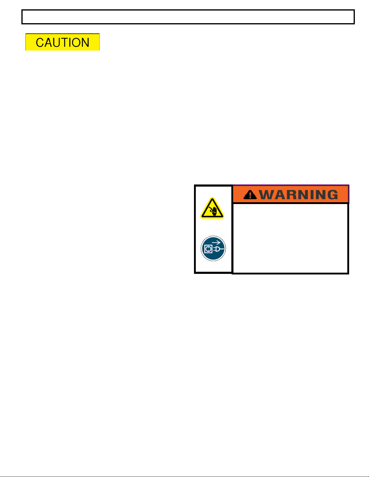
ATTENTION:
The table to the right provides
definitions of the signal words that
can be found throughout this
manual. These signal words are
used to express the severity of the
hazard at hand. The signal words
are generally used in conjunction
with safety symbols that correspond
to the text for that particular hazard.
As you read this manual, refer back
to this table when you are unsure of
the signal word definition.

Page 3 of 16
ELECTRICAL SHOCK HAZARD
FIRE HAZARD
•Serious injury or death may
occur.
•Do not use in locations
containing hazardous or
explosive atmospheres.
•Do not use outdoors in wet
conditions and in
unprotected locations.
This unit is a compact, self-contained, high-
efficiency portable evaporative cooler capable of
lowering existing temperatures by as much as 26
degrees. The unit draws air across water-
saturated high-efficiency cooling pads, causing a
gradual evaporation of the water, thereby
removing heat from the air. The 10-gallon
reservoir provides hours of operation without a
water supply.
Evaporative cooling is also environmentally
friendly, since it does not use chlorofluorocarbons
(CFC’s), and therefore does not contribute to
ozone depletion.
GENERAL DESCRIPTION & USE
Benefits
•Significantly reduces air temperatures
and generates a cooler and more
comfortable working environment
•Compact portable cooling system with
quiet fan axial blower design
•Easy to operate and maintain, plus an
economical solution for low cost spot
cooling
•Cooling media pad contains a paper
treated CELdek material with a rigid
protective edge coating (Munters MI-T-
edg ®) to extend the life of the pad,
plus provide added weather and algae
protection, durability, and formulated
to withstand repeated cleaning without
damage to the pad
•Ready to plug into any 120VAC
receptacle and hooks up to any
standard garden hose for direct water
supply
•Applications would include workshop
environments, material handling areas,
automotive shops, office areas, and
many more!
Features
•Reduces air temperatures up to 26-
degrees
•Cools an area of approximately 900
sq. ft. (30’ x 30’)
•4” thick highly efficient cooling pads
•Four 3” diameter swivel bearing
wheels, two locking, for easier
portability and positioning over many
surface types.
•Indented top for tool & product
placement
•Internal reservoir with water capacity
of 10 -gallons for remote applications,
includes oversize inlet opening for
reservoir filling.
•Auto fill hose connector for continuous
use with a garden hose
•Includes 17’ long cord with ground
fault 120 volt plug

Page 4 of 16
SPECIFICATIONS
Air Volume 3800-CFM (2200-CFM Low), 700-FPM @ 6FT
Fan Motor Variable
Cooling Media Type CELdek high cellulose paper treated media pads for effective cooling and resistance
to edge degradation. Cross-fluted design induces highly turbulent mixing of air & water
for optimum cooling and enhanced self-cleaning.
Cooling Media Size 18" x 18" and 4" thick
Water Reservoir
Capacity 10 - gallons
Switch Variable
Cord 17’ long, 18 ga. 3-conductor cord GFCI
Protective Guard CSW-12VD Oscillating
Power Supply 120-VAC; 60 Hz; 3-Amps
Unit Dimensions 21-1/4" wide x 27-1/2" tall x 23” deep
Unit Weight 51 lbs. (without water in reservior)
Water Supply Standard garden hose connection or hand fill reservoir
WIRING

Page 5 of 16
To understand how the portable evaporative cooler works a basic understanding of psychrometrics is necessary.
Psychrometrics is the branch of thermodynamics devoted to the study of air and water vapor mixtures. The
psychrometric chart is a graphical representation of properties of moist air. To illustrate how the unit operates, some of
the relevant properties are described in this section followed by a sample application.
Dry-bulb temperature is measured with a thermometer. Dry-bulb temperature lines on the psychrometric chart are
the vertical lines. The wet bulb temperature is the lowest temperature that can be reached by evaporating water
into the air.
Dew-point temperature is the temperature to which a
given sample of air must be cooled so that moisture
will start condensing out of it. When air is saturated,
the dry-bulb, wet-bulb, and dew-point temperatures
will all be equal. The horizontal lines show the dew-
point temperature on the psychrometric chart.
Relative humidity is the amount of moisture in the air
relative to the amount of moisture the air would hold if
saturated at that dry-bulb temperature. Percent
humidity is not the same as relative humidity and is not
used in HVAC design. This graph shows the relative
humidity curves on the psychrometric chart.
HOW EVAPORATIVE COOLING WORKS
DRY BULB TEMP
WET BULB TEMP
DEW POINT TEMP

Page 6 of 16
Inspect your unit for any concealed shipping damage and report it immediately to your carrier. In addition to our
evaporative cooler the following items are included in a hardware pack and will need to be installed before
operating the unit.
UNPACKING
Non-Swivel w/ lock (qty. 2)
The following example illustrates the use of the psychrometric chart as it relates to evaporative cooling. Since
all of the items described above are properties, any two of them describe a state point on the psychrometric
chart. Once this point is determined, the values of all the other properties can be read from the chart. The
example below shows a Mollier type psychrometric chart for atmospheric pressure.
The dot shown is a state point and the following properties are known about the air/water mixture at this state.
Take the air/water mixture described by the state point above, with a dry-bulb temperature of 97°and 43% relative
humidity, for example. As the air passes through the cooling media on the unit, moisture is added to the air
increasing the relative humidity. This increase in relative humidity brings a decrease in dry bulb temperature. When
the relative humidity is raised to 70%, the dry bulb temperature has dropped to 86°F. When the humidity level
approaches 100%, the dry bulb temperature has dropped nearly 20°F to 78°F.
78°F
71°F
97°F
43%
WET BULB TEMP
DRY BULB TEMP
Dry-bulb temperature: 97°
Wet-bulb temperature: 78°
Dew-point temperature: 71°
Relative humidity: 43%
Swivel Casters: (qty. 2)

Page 7 of 16
Casters (4)
Screws (2)
Bottom of unit
Screws: (qty. 8)
ASSEMBLY
Wheel Assembly
Tools required: 7/16” nut driver
1.) Turn unit over and place on cardboard to
protect finish
2.) Align wheel plate with embedded nuts on
bottom of housing
3.) Attach using (2) screws
4.) Repeat steps 2 and 3 for each wheel
ELECTRICAL SHOCK HAZARD
•Serious injury or death may
occur.
•Disconnect from electrical
supply before and during
assembly of this product.
Pad Installation
1.) Remove pad retainer bar
2.) See page 12
Pads
Washer (2)
Screws (2)
Pad retainer bar

Page 8 of 16
Garden hose connection:
This unit comes equipped with pressure regulator a female garden hose adapter that can be connected to any standard
garden hose. The float will automatically maintain the correct water level. DO NOT over tighten as this may cause the
float assembly to rotate resulting in over filling of reservoir.
Stand-alone:
This unit can also be manually filled and moved into position. To fill the unit; simply remove the fill cap located on the
side of the housing, fill with water, and replace the cap. NOTE: Do not fill the reservoir past the max water line. Water
can easily spill from inside the unit when rolling the cooler on uneven surfaces or if the reservoir is overfilled.
-Do not connect this unit to any water
source where the water pressure exceeds 60
psi. This will cause permanent damage to
the unit. Pressures above 60 psi must use a
pressure regulator. A pressure reducing
valve is installed on the float inlet.
-Do not fill the reservoir past the MAX water
level line indicator.
CONNECTING THE WATER SUPPLY
ELECTRICAL SHOCK HAZARD
•Serious injury or death may
occur.
•Disconnect from electrical
supply before and during
assembly of this product.
This cooler comes equipped with a 120-volt
power supply cord and should only be plugged
into a 120 VAC, 60 Hz branch circuit that
includes a properly sized over current protection
device (fuse or circuit breaker). Consult a
licensed electrician if there is a question about
adequacy of the electrical supply.
EXTENSION CORDS
Use only 3-conductor extension cords of
14AWG to 25 ft., 12AWG to 50 ft. & 10AWG to
100ft. length maximum. Do not use the
extension cord powering this cooler to power
any other appliances or electrical loads.
CONNECTING THE ELECTRICAL SUPPLY
ELECTRICAL SHOCK HAZARD
•Serious injury or death may
occur.
•Make certain the power
source conforms to
specifications on data label.
•Do not connect plug to power
supply without cooling pads
installed and fastened in
place.
Page 9 of 16
Initial start-up:
Clean out the Sump: Remove any foreign
material in the sump before start up. It is normal
for some debris to accumulate in the sump. It is
best to flush out the sump with water to clear any
debris.
Filling the unit with water: Once the unit
has been hooked up to a water source, turn the
water supply valve on and the unit will fill with
water. The float valve will shut off the water flow
when the reservoir is filled.
START-UP PROCEDURE
Do not operate the pump when the reservoir is dry. This will cause the pump to
fail and also void the warranty.
There are 4 factors to consider when determining where to place your evaporative cooler.
1. Fresh air supply: The inlet side of the unit (pad side) requires a constant, uninterrupted supply of fresh air for
maximum performance. A distance of 3 ft. of clear space is recommended.
2. Discharge airflow: The cool air discharged from the unit should be free of obstruction to allow the air to
circulate in order to maximize the cooling zone.
3. Ventilation: Allow cooled air to circulate away from discharge area of cooler. This ensures that the unit does
not re-circulate air that has already been through the evaporative cooling process.
4. Placement: The unit must be placed on a level surface to operate correctly. The units create an oval shaped
air pattern that can reach out as far as 20 feet. Obstacles such as racks and workbenches may interfere with
the cooling zone. An attempt should be made to locate the unit in such a manner that interruption of the air
pattern is held to a minimum. Multiple units may be required to cover large areas.
ELECTRICAL SHOCK HAZARD
•Serious injury or death may
occur.
•Disconnect from electrical
supply before servicing this
product.
Annual start-up:
At the beginning of each cooling season follow the same procedures as the initial start-up with some possible
exceptions. If the media was removed for the winter, it will have to be replaced (note instructions below on media
replacement). Check the condition of the media. If the flutes of the media are clogged with buildup of alkali deposits or
are otherwise damaged, consider replacing the media. This is the best time to make this decision while the unit is not
being used and may not be as critically needed.
Starting the pump: Allow the reservoir to fill before turning the pump on. Once the reservoir is full, the
pump switch may be turned to the ‘ON’ position.
Initial Washing of the Cooling Media: The media should be washed for several hours by running
the pump without any airflow through the media. This washing action will clean out any debris in the media
as well as reduce any odor and improve wetting ability.
Break in Period for Cooling Media: The media will reach its peak operating condition after about
100 hours of operation. The chemical constituency rigidifying agents in the media will then be set and will
not leach out further. Ignore any coloration in the water during this initial period.
If a strong odor persists, run the pump to flush the media with water, without airflow through the media, until
the odor disappears.

Page 10 of 16
ODOR CONTROL
One of the few inconvenient aspects of evaporative cooling is the control of unpleasant odors.
There are two primary causes of these odors:
1. Initial wetting of new pads
2. Poor maintenance and storage behaviors and/or poor quality water.
Your EVAP-series cooler has been delivered with pads that have never been wet. The same is
true of replacement pads. The resins and adhesives used to create these pads will give off an
odor during initial use that can last for a week or more. This can’t be avoided but it can be
minimized. As the cooler is used over time, algae and bacteria growth can occur. This can also
be minimized. Below are recommended actions to be taken to address noticeable odor due to
the above causes.
Odor from Initial Wetting of Pads
1. At first use of your new cooler or after
installing new replacement pads, make
certain there is lots of fresh air available
to the cooler.
2. Add one capful of liquid laundry fabric
softener to the water in the bottom
reservoir of the cooler.
3. The odor from initial wetting of pads
should disappear in approx. two weeks
of operation.
4. If odor does not disappear after two
weeks of operation, follow the steps for
“Periodic Odor Maintenance”.
Periodic Odor Maintenance
1. Make certain the cooler is full of fresh
water.
2. Flush the pads for 3 – 4 hours by
operating the pump only with the fan
off. Adjust flow control valve for
maximum rate of recirculating water
flow.
3. After flushing, empty the reservoir
through the front drain and clean out
any residual particulate in the
reservoir.
4. Refill reservoir with fresh water and
proceed to use the cooler.
5. Repeat the above steps as necessary
to eliminate odor.

Page 11 of 16
MAINTENANCE
Algae/Bacterial Control
Control with chemicals. Chlorine is the most
commonly used chemical to control organisms. It is
potentially dangerous and should be used with great
caution. One of the best methods to introduce chlorine
into the water circulation system is on the pressure side
of the pump on a continual or timed basis.
Note: Consult water treatment experts before
attempting chemical water treatment. Neither media
manufacturers’ nor equipment manufacturers’
warranties cover damage due to chemical water
treatment and warranty may be voided when chemicals
are used.
Other chemicals suitable for organism control include
hydrogen peroxide, bromine based oxidizers, and other
commercial products. It is important to maintain a 6 to 9
pH level after treatment.
Control without chemicals. With water, sunlight, and
nutrients, most organisms can survive. The water in the
media can be allowed to dry out and any organisms
living in the media will become dry and flaky. This can
then be flushed out at the next start up of the unit.
Shading the media will prevent the sunlight from
encouraging the growth of organisms. Nutrients are
available from the air itself, however in some instances,
phosphates and fertilizers are carried in the air stream
and should be avoided.
Flushing the media with fresh water and dumping
the sump water periodically is the best preventative
measure that can be taken.
This flush and dump action will actually prevent alkali
deposits and algae/bacteria from growing. There are
also some non-recirculating water distribution systems
available that provide a constant flushing/dumping
action.
Water Chemistry
Hard water contains relatively large amounts of
minerals, primarily calcium. A sample of water can
contain only a specific maximum amount of dissolved
solids in solution. If these concentrations increase
beyond a certain level, the excess minerals precipitate
out as a solid material. This precipitation will appear
as the familiar white residue left on the face of the
media. It is commonly referred to as alkali, calcium
depositions or salts. The same process occurs in the
desert when water collects in depressions and since
only pure water evaporates the minerals are left
behind. These are commonly referred to as “dry
lakes” or “salt flats”.
The build up of these minerals on the face of the
media does not because a problem until the airflow is
restricted. There is no easy way to remove these
deposits. The best solution to this problem is
preventive rather than corrective action and usually
requires simple actions such as media flushing with
fresh water and periodic dumping of the sump water.
Soft water is on the opposite side of the scale for
water chemistry as compared to hard water.
Basically, removing or diluting the effects of the
calcium in the water creates soft water. Soft water is
not to be confused with pure water. Pure water does
not contain or contains very small amounts of
minerals found in either hard or soft water. While
hard water can leave deposits in the media, soft water
can cause harm to the media by leaching out the
rigidifying agents. Either water condition can have
some adverse effects on the media.
PH Range. A pH range of 6 to 9 is the acceptable
range for the media, the closer to the center the
better. The re-circulating system of the water
distribution allows the mineral content in the sump
water to become more and more intensive because
the same water is re-circulating. The pure water is
lost to evaporation while the minerals just continue to
build up. TDS is the abbreviation for “Total Dissolved
Solids” and represents, as the name implies, a way of
identifying a measurement of the mineral content.
CHEMICAL BURN HAZARD
POISONOUS GAS HAZARD
•Serious injury or death may
occur.
•Read, understand and follow
all chemical manufacturers’
instructions when using the
chemicals noted in these
pages.

Page 12 of 16
CHEMICAL BURN HAZARD
POISONOUS GAS HAZARD
•Serious injury or death may
occur.
•Read, understand and follow
all chemical manufacturers’
instructions when using the
chemicals noted in these
pages.
Removing the cooling media:
In order to perform any maintenance on internal
components the cooling pads must be removed to
access the inside of the unit.
Media removal / replacement is simple, if you follow
these instructions! The media is soft when wet so be
very careful when handling. The media has two
separate flute angles, which are transverse to each
other and alternate across the face of the media.
One flute is 45°and the other is 15°. The alignment
of the flute arrangement in relation to the direction of
airflow is critically important. The 45°flute must be
aligned upwards in the direction of the airflow. The
15°flute must be aligned downwards in the direction
of the airflow.
1. Using a 5/16” nut driver, remove the (2)
screws holding the pad retainer bracket in
place. Save all hardware.
2. The pad may be tilted out of the unit and
lifted out of the drain tray.
Note: Reinstall pads correctly; refer to sides of
pad material for airflow direction.
To keep your unit operating at peak efficiency, ensure that
the cooling pads are kept clean and dust-free. Dust and
other particles have an adverse effect on the media’s
ability to introduce water into the air stream. If the pad
surface becomes dirty or dusty, clean with a soft brush
and water.
Daily maintenance:
At start-up: It is best to run the pump several minutes
before the fan is started to clean out any debris on the
media.
At shut-down: When shutting down your evaporative
cooler at the end of each workday, the pump should be
turned off approximately 15 minutes before the fan is
turned off. This will allow the pads to drain and dry out.
This simple guideline will ensure long and efficient pad life
as well as help to control mildew and bacteria growth.
Periodic maintenance:
Depending on how often the unit operates, this procedure
should be performed anywhere from every week for
heavy use to monthly for light use.
1. Drain reservoir.
2. Remove cooling pads.
3. Clean out reservoir with either a towel or wet/dry
vacuum.
4. Reinstall pads and pad retainers.
ELECTRICAL SHOCK HAZARD
•Serious injury or death may
occur.
•Disconnect from electrical
supply before servicing this
product.
Annual shutdown / Storage:
1. Wash down the media to flush out all the debris.
2. Open the drain in the sump to drain out any
standing water.
3. Wash the interior of the unit to remove any
algae or micro-organisms as well as calcium
deposits. A weak dilution of muriatic acid will
help clean the alkali (calcium) deposits.
Commercial chlorine will kill and clean out the
algae.
4. Store the unit in a dry area and cover if possible
to prevent dust build-up.
Airflow
Direction
Screws
Pad retainer
Pad material

Page 13 of 16
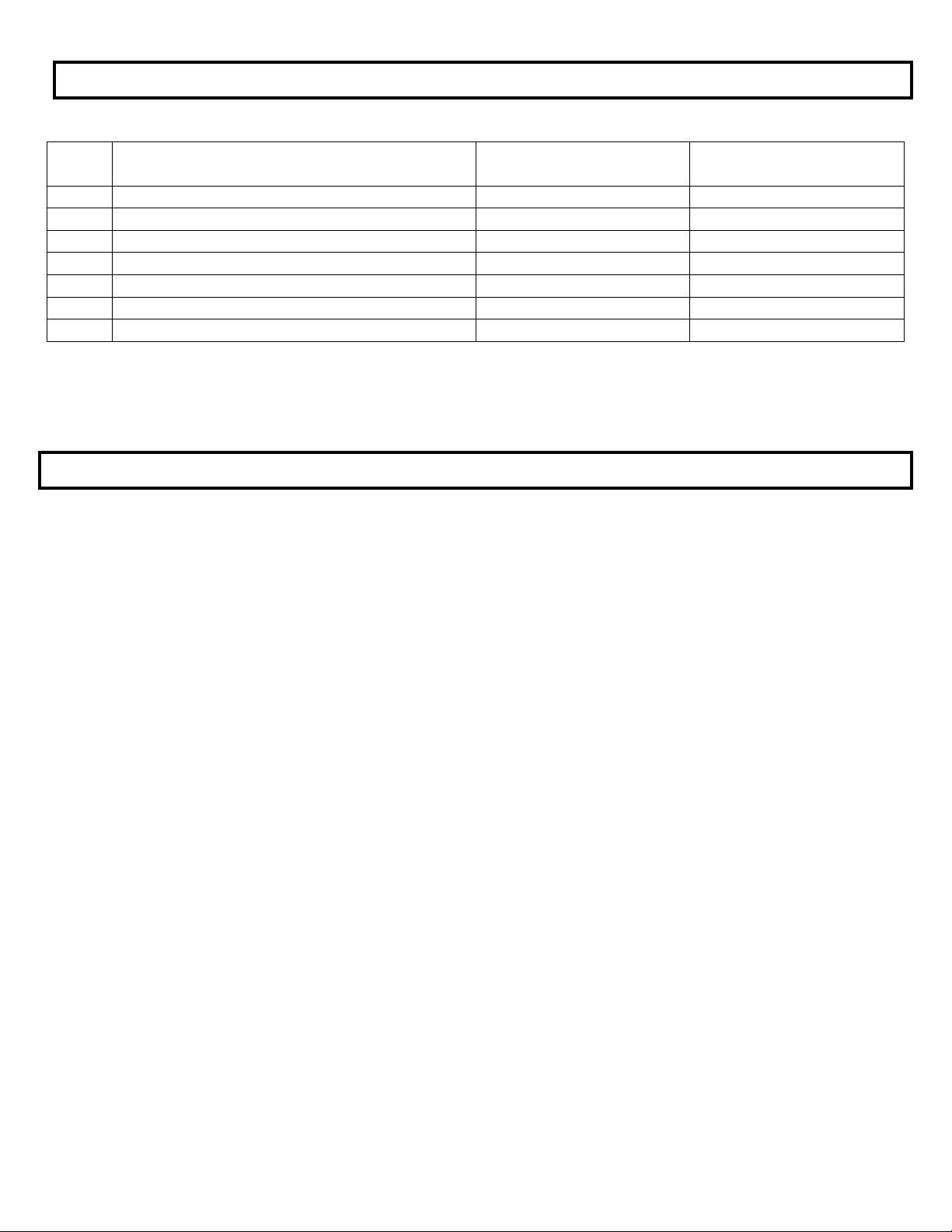
TROUBLESHOOTING
Fan System: The fan system consists of two primary elements: Fan Blade and Motor
Problem
Check
Solution
Fan won’t run and makes no sound.
Power cord, extension cord, switches, and circuit
breaker.
Reconnect power or extension cord.
Reset breaker.
Fan motor won’t run and makes a
humming sound.
Motor stalled (will not turn by hand).
Replace motor.
Breaker trips or fuse blows when fan is
started.
Motor stall.
Check power source for min. 115v/10 amp.
Extension cord adequacy.
Replace motor.
Upgrade power supply.
Replace with heavier cord.
Motor overheating and shutting off.
Restarting several minutes later.
Extension cord gauge too small.
Inlet air obstructed or too close to wall.
Faulty motor.
Replace with heavier cord.
Provide additional inlet clearance.
Replace motor.
Fan motor won’t run and switch makes
soft clicking sound.
Switch making good contact.
Replace switch.
Water Systems: The water delivery system consists of four primary elements: Water Hose, Float Assembly, Pump,
and Water Distribution Channel.
Problem
Check
Solution
Floor at side of the unit is wet.
Water inlet hose is loose at supply
hose.
Tighten connections and/or replace
hose washers.
The unit overflows from reservoir.
Float valve hose is loose at bulkhead
fitting or at float valve.
Water pressure is too high to allow
float valve to shutoff (60psi max).
Float valve is not seating properly.
Tighten connections and/or replace
hose washers.
Reduce water pressure by adding an
inline pressure reducer.
Check float valve.
Replace float
Water leaking from drain valve.
Make sure drain nut is secure.
Tighten drain nut.
Too many dry streaks in the pads.
Holes in water distribution tray are
blocked.
Remove distribution tray and clean
Water spitting from the unit.
Hose connection loose.
Tighten hose.
Replace hose and washer.
Pump motor will not run when switch
is turned on.
Check switch, cord and circuit
breakers.
Replace switch and reset breaker.
ELECTRICAL SHOCK HAZARD
•Serious injury or death may
occur.
•Disconnect from electrical
supply before servicing this
product.
Page 14 of 16
ITEM
NO.
DESCRIPTION
PART NO.
QUANTITY
1
FAN ASSEMBLY
CS-F12-VD 60HZ
1
2
ON/OFF SWITCH
CS-E110
1
3
VARIABLE SWITCH
CS-E187-VD 60HZ
1
4
PUMP
CS-E12-101
1
5
FLOAT
CS-P053.1
1
6
PAD MEDIA KIT
CS-A12-101
1
COMMON REPLACEMENT PARTS
DO NOT DISCARD FAULTY PARTS! THEY MUST BE RETURNED IN ORDER TO RECEIVE WARRANTY CREDIT
WARRANTY
WARRANTY
Your COOLSPACE unit is guaranteed against any defective material or workmanship
for a period of 12 months from your date of original purchase. Please call (800) 557-
5716 to receive a returned goods authorization number to return and receive any
defective parts. Shipping costs for returns are at the expense of the customer.
It is our goal to have satisfied Customers, and to provide you with any support you may
need. If you have any questions about our product, operation or are having technical
problems please call 1-800-557-5716.
IN CASE OF PRODUCT FAILURE:
Please have the following information ready when you call:
1. Model Number and Serial Number.
2. Proof of purchase.
3. Description of the problem encountered with product.
SELLER'S LIABILITY
Seller will not be liable for any loss, damage, cost of repair, incidental or
consequential damages of any kind, whether based on warranty, contract or
negligence, and arising in connection with the sale, use or repair of the Products.
Seller's maximum liability shall not in any case exceed the contract price for the
Products claimed to be defective or unsuitable.
RETURNED GOODS
Equipment may be accepted for return with in 90 days of shipment, when
authorized by us with our return labels. Request necessary permission and
special Return Authorization Tags. Currently listed equipment in new and unused
condition, and in factory sealed cartons, may normally be returned for full credit
less 25% (minimum charge $20.00) charge for handling, repacking and
restocking, and less transportation charges both ways, at net prices prevailing at
time of purchase or time of return, whichever is lower. Advanced Radiant
Systems, Inc., however, reserves the right to refuse any return, at our discretion,
and is not responsible for error. All special, custom made or equipment with
special finishes, and modified versions of cataloged numbers are not returnable.
All returned merchandise is subject to inspection. Unsalvageable and damaged
merchandise will be credited at salvage value or less costs of repairs.
DAMAGED GOODS
Minimum charge on replacement will be waived if order is accompanied by
copy of proof of claim submitted to carrier. No repair, replacement, or other
adjustment by the customer is authorized by us, unless so stated in writing
by our Sales Service department.


Page 15 of 16
COOLSPACE®Warranty Form
Date Purchased: __________________________
Purchased From: _______________________________________________
Model Number: CSW- __________ Serial Number: ___________________
Company: _____________________________________________________
Contact: _______________________________________________________
Address: _______________________________________________________
Phone Number: __________________ Fax Number: ___________________
You must complete this form and return within fifteen (15) days of initial
purchase to validate your cooler’s warranty. Please call COOLSPACE
®
(800) 557-5716 if you have questions.
Please fax or mail this completed form to:
Fax to: (317) 485-0118
Mail to: COOL-SPACE
®
Warranty Dept.
315 N. Madison St.
Fortville IN 46040
Submit online: www.COOL-SPACE.com under the CONTACT tab.
www.cool-space.com


Page 16 of 16
IMPORTANT NOTICE:
DO NOT RETURN TO PLACE OF PURCHASE.
Please call 800-557-5716 for technical service support and warranty information
315 North Madison Street, Fortville IN 46040
Phone: 317-577-0417 – Fax: 317-485-0118
1-800-557-5716
www.cool-space.com
sales@cool-space.com
REV 06/14jw PN CSW-VD MANUAL
If you have questions about the product you have
purchased or would like to leave us feedback, please
contact us via our website www.cool-space.com or by
calling 1-800-557-5716.
Table of contents
Popular Air Cleaner manuals by other brands


Aprilaire
Aprilaire 1510 installation instructions

Philips
Philips GP7101 user manual

Apriaire
Apriaire 2210 owner's manual

Rinnai
Rinnai Airo AAP240 Operation & installation manual

AllerAir
AllerAir AirMedic+ Series Operation and maintenance manual

AirScape
AirScape HEPA TOWER Installation and operation manual