Advanced Wireless Communications AW-NCB4100 User manual
User Manual
AW-NCB4100(W)
Wireless Nurse Call Box

The AW-NCB4100(W) ODIN Care wireless nurse call box is a battery powered,
wireless control signal, low prole, surface mount nurse call box. Because it
is wireless, this call box can be installed in a variety of locations without the
expense of cabling. This nurse call box becomes part of the ODIN Care system
infrastructure and is an initiator that provides activation and deactivation of
the ODIN Care system. The AW-NCB4100(W) is white in color and has a gray
faceplate label. Status LED’s are located in the upper left-hand corner of the
call box and provide easy visual conrmation of the call box status.
Product Summary
This manual should be read to ensure that the user understands the
operation of the AW-NCB4100(W).

Call Box Functions
The AW-NCB4100(W) is designed to be used in a wide variety of applications
and the means of activating the call box are as follows:
Large Blue Button Press
Will activate the call box primary alarm transmission. This large button is easy
to see and easy to activate. Press the large blue button and the call box will
initiate its wireless alarm transmission.
Pull Cord Activation
All AW-NCB4100(W) are equipped with a pull cord installation option. Simply
connect an appropriate pull cord to the “pull string” pig tail located at the bottom
of the call box. Pulling the pull cord will activate the primary alarm transmission.
Dual Bed Cord Functionality
The AW-NCB4100(W) call box can independently accommodate up to two
bedside call cords. These cords connect to the nurse call box with magnetic
breakaway modules. These magnetic breakaway modules provide a cord
release mechanism that prevents damage to the call box or cord if pulled
aggressively from the call box.
Bed Cord Port One
The left port of the call box will activate the primary alarm transmission.
Bed Cord Port Two
The right port of the call box will activate the secondary alarm transmission.
If a bed cord is pulled from the call box, the call box will activate as if the button
has been pressed. The call box will not be able to be reset until the bed cord
and breakaway module have been reinstalled into the appropriate magnetic
breakaway port.
Note: If bed cords are not used with the nurse call box, port jumper plugs must
be installed in the unused magnetic breakaway ports of the call box.
Small Orange Button Press
On the front of the call box is a dual-purpose orange button. Its functions are as
follows:
Reset Button
To reset an active call box, simply press the orange reset button. The LED’s will
ash green if a successful reset has been initiated.
Resident Check-In Feature
If utilized, the resident check-in feature is activated by pressing the reset button
when the call box is idle. Doing so will cause the status LED’s to ash yellow
and will initiate a resident check-in transmission from the call box. This feature
must be activated within the ODIN Care system.
1
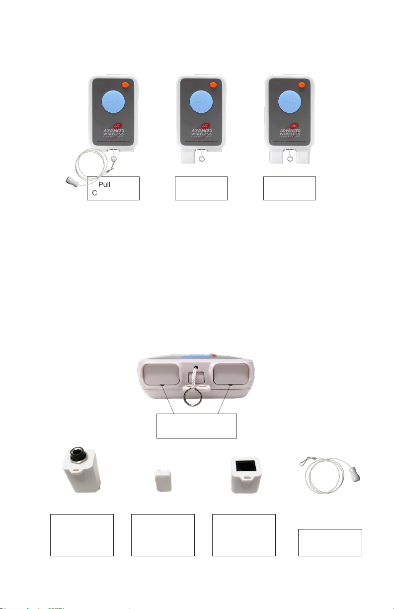
Call Box Congurations
Changing Call Box Congurations
To change the application conguration of a call box, Magnetic Breakaway
Ports will have to be recongured.
Pull Cord Call Box – Must have both Magnetic Breakaway Jumper Plugs
installed.
Single Bed Call Box – Remove the Magnetic Breakaway Jumper Plug from the
left Magnetic Breakaway Port.
Dual Bed Call Box – Remove both Magnetic Breakaway Jumper Plugs
To remove a Magnetic Breakaway Jumper Plug – Use a small screwdriver, or
equivalent, to access the small opening at the bottom center of the call box
Magnetic Breakaway Port. Gently ‘pry’ outward to remove the Jumper Plug.
2
Jumper Plug Removal
Access Holes
900294
Magnetic
Breakaway
Module 1/4”
Phono Jack
900274
Magnetic
Breakaway
Jumper Plug
900293
Magnetic
Breakaway
Module RL-45
Jack
920801 3 FT
Pull Cord
Washable
920818 5 FT
Single Bed
Conguration
900292
Dual Bed
Conguration
900295
Pull Cord
Conguration
900291
3
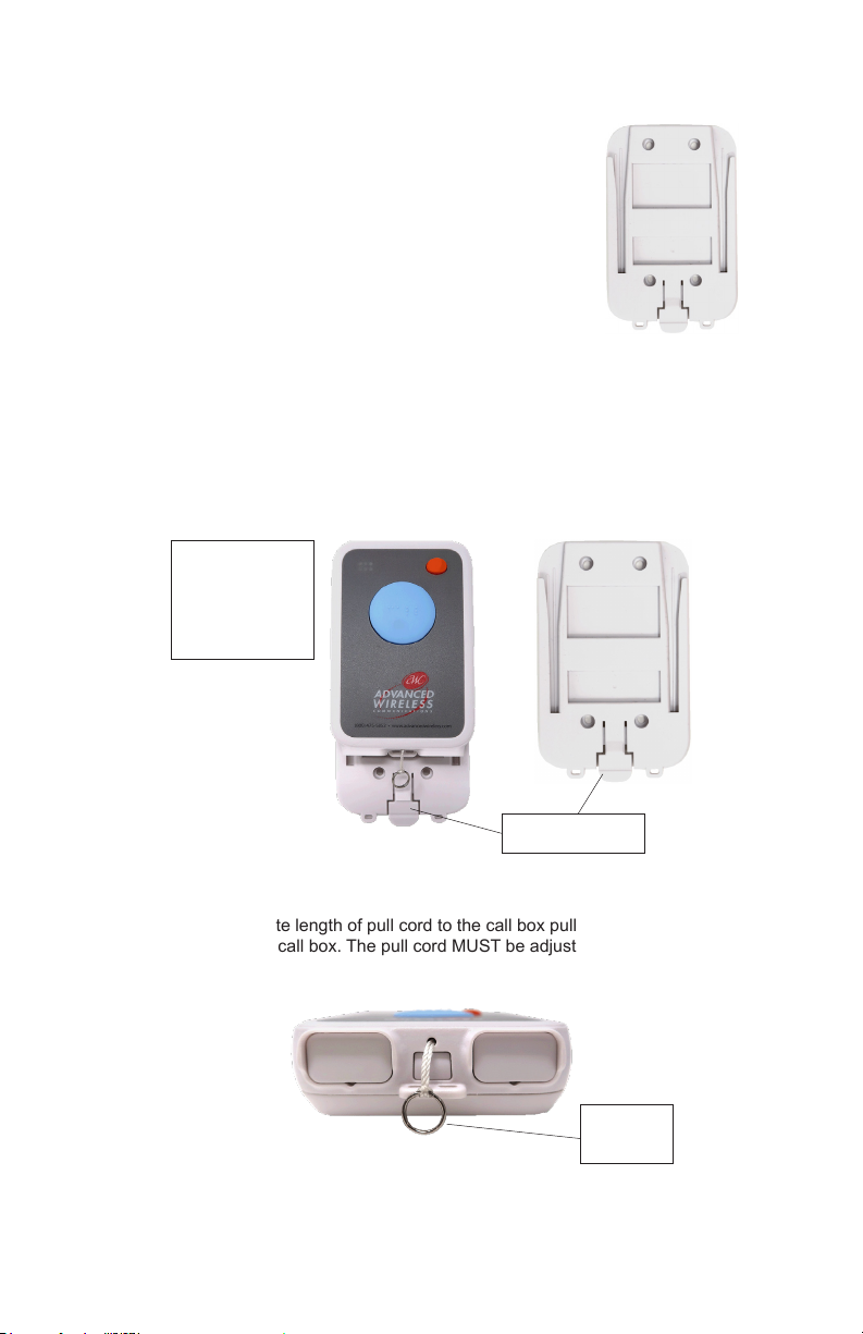
Mounting Bracket Installation
The AW-NCB4100(W) call box should be mounted
onto at surface using the appropriate mounting
screws/hardware for the surface type. The mounting
bracket screw holes are designed to utilize a standard
#6 or #8 pan head screw. There are four available
mounting hole locations. The call box inserts at the top
of the mounting bracket and slides down to lock into
place. When installing the bracket, make sure the
mounting bracket release tab is at the bottom.
Installing AW-NCB4100(W) To Mounting Bracket
The call box is installed onto the mounting bracket from the top down. Line
up the back of the call box to the top of the bracket and slide the call box
downward. The call box will lock into place in the mounting bracket.
To remove the call box from the mounting bracket, press the lock release tab
and slide the call box up and out of the mounting bracket.
Pull Cord Installation
Install the appropriate length of pull cord to the call box pull cord pig tail located
at the bottom of the call box. The pull cord MUST be adjusted to be within 6
inches of the oor.
Install the call
box from the top
and slide down
until the locking
tab engages
Locking tab
Pull Cord
Pig Tail

4
Battery Replacement
Remove the call box from the mounting bracket. Firmly press the rear housing
release button while gently pulling outward on the bottom rear housing cover
of the call box. When the release button is pressed far enough inward, the rear
housing cover will release and hinge open. The rear cover will hinge at the top
of the call box.
This will expose the internal electronics of the call box. The battery is located
near the center of the call box and can easily be replaced at this time.
Note: When replacing the battery, pay close attention to the battery polarity.
There is a large ‘+’ and large ‘–’ located on the circuit board that identies the
proper battery polarity. Install the ‘+’ side of the battery to the ‘+’ side of the
battery holder.
Note: The battery is a 3.6 volt lithium battery. The correct battery replacement
must be used. Even though the battery is the same size as an alkaline AA
battery, an alkaline battery WILL NOT work in this call box.
Multi-Function LED Indicator Lights
No LED illumination – call box is idle
Single red ash – once per second, to indicate an active primary alarm (bed
port 1, pull cord, or button press activation)
Two short red ashes – two per second, to indicate an active secondary alarm
(bed port 2)
Three short red ashes – three per second, to indicate that both primary and
secondary alarms are active
Three green ashes – when pressing the reset button of an active call box to
provide clear conrmation to the respondent that the call box has been ‘cleared’
and returned to an idle condition.
Three yellow ashes – to provide acknowledgment to the resident that the
‘resident check-in’ feature has been sent. (This is initiated by the press of the
call box reset button when the call box is idle.)
Rear Housing
Release Button
Battery
Li-Ion Battery
3.6V AA

5
Call Box Specications
Without Mounting Bracket: With Mounting Bracket:
Height: 5.0625” Height: 5.25”
Width: 3.25” Width: 3.4375”
Depth: 1.375” Depth: 1.625”
Weight: 5.7 oz. Weight: 7.1 oz.
Battery: 3.6V lithium
Humidity: Up to 90% non-condensing
Temperature: 20° F to 140° F
Freq. Range: 902-928 MHz
Auto Check-In: 3 minutes
The AW-NCB4100(W) is not water resistant – do not submerge in water.
Call Box Cleaning Recommendations
Never use strong cleaning chemicals to clean the surface area of two-
way radios or call boxes. Some examples would be: acetone, bleach,
window cleaner, degreasers, hand sanitizers, nail polish remover or like
products. Referencing the above cleaning procedures; Advanced Wireless
Communications, Inc. does NOT imply that any of these cleaning procedures
provided is eective in removing or killing potential contaminants or viruses from
the radio surface. Rather, these recommendations are intended to provide the
radio user with acceptable alternatives for a cleaner physical environment.
Preferred Cleaning Method –
Use a warm, damp cloth (water only) to wipe all surface areas of the call box.
The cloth should be damp only, not dripping water. Never hold the call box
under a running water faucet or submerge in water. After wiping, if moisture is
seen on the surface of the call box, wipe with a dry cloth to speed drying.
Acceptable Cleaning in Moderation –
Use a mild dish soap and warm water mix, thoroughly submerge the cloth in the
soap and water solution. Remove the cloth and wring all water out of the cloth.
The cloth should be damp only, not dripping. Never hold the call box under a
running water faucet or submerge in water. Wipe all surface areas of the call
box. After wiping, if moisture is seen on the surface of the call box, wipe with a
dry cloth to speed drying.
Aggressive Cleaning Method –
Note: Over time, this method can cause undesirable cosmetic eects to the
label and adhesive areas. It can also cause discoloration to plastics.
Use an over the counter, 75% Isopropyl alcohol concentration to dampen a
cloth. Damp only, not dripping alcohol. Wipe all surface areas of the call box.
Alcohol residue will dry quickly.
NEVER apply the 75% Isopropyl alcohol directly to the surface area of the
call box. Never submerge call box in alcohol.

6
Replacement Parts List
914459 Battery, 3.6 volt Lithium
916200 Bed cord, push button, white, 10 foot, RJ45 plug
916187 Bed cord, push button, white, 10 foot, ¼” phono plug
900274 Magnetic Breakaway, jumper plug
900293 Magnetic Breakaway Module, RJ45
900294 Magnetic Breakaway Module, ¼” phono plug
900273 Mounting bracket, Nurse Call Box
900291 Nurse Call Box assembly, Restroom conguration
900292 Nurse Call Box assembly, Single bed, RJ45 Breakaway Module
900295 Nurse Call Box assembly, Dual bed, RJ45 Breakaway Module
920801 Pull cord, white, washable, 3 foot
920818 Pull cord, white, washable, 5 foot
915722 Rubber Keypad, large blue and small orange button

703119©2020 Advanced Wireless Communications. All rights reserved.
(952) 469-5400 / Toll Free: (800) 475-5852
20809 Kensington Blvd
Lakeville, MN 55044-8353
www.advancedwireless.com
This manual suits for next models
1
Table of contents
Other Advanced Wireless Communications Personal Care Product manuals


