Ligoo EK-YT-21 User manual
EK-YT-21 BMS
- 0 -
Prominent Advantages

EK-YT-21 BMS
- 1 -
Foreword
Foreword
Thank you very much for choosing our EK-YT-21 BMS (BMS: Battery Management System). In order to help you install,
use and maintain the product better, please read our user manual (hereinafter referred to as manual) carefully before installing
and using it.
EK-YT-21 BMS is a new generation of BMS specially developed for light cars, mini-cars, space vehicles and electric
motorcycles. Because of the low working voltage of light cars, mini-cars, space vehicles system, less strings of battery pack
can meet the requirement of the system. Due to limited total volume, the electric motorcycles require a kind of BMS with
smaller volume, more functions and more stable performance.
EK-YT-21 BMS can also be applied to forklift trucks, road sweepers and other special vehicle as emergency power supply
for communication base station BMS etc.
With unique design structure of collection and control in collection, EK-YT-21 BMS reduced its volume greatly, lower the
requirement for installation space; its high integration degree of the system makes wiring installation more concise .
EK-YT-21 BMS also provides communication mode of CAN Bus, RS485 Bus, and perfect balance failure protection and
balance control strategy.
1.1 Suggestion
This manual contains important information that the users must grasp, if customers are not in strictly with the manual
direction to install, use and maintain the product, our company would not take any relevant consequence and responsibility.
1.2 Qualifications and Relevant Certificates of Company
1.3 Statement
To ensure the accuracy, this manual has been validated and rechecked.The description and direction of EK-YT-21 BMS in
this manual is correct ,but because of technical improvements, the EK-YT-21 BMS and the manual may change without prior
notice.
EK-YT-21 BMS
- 2 -
Prominent Advantages
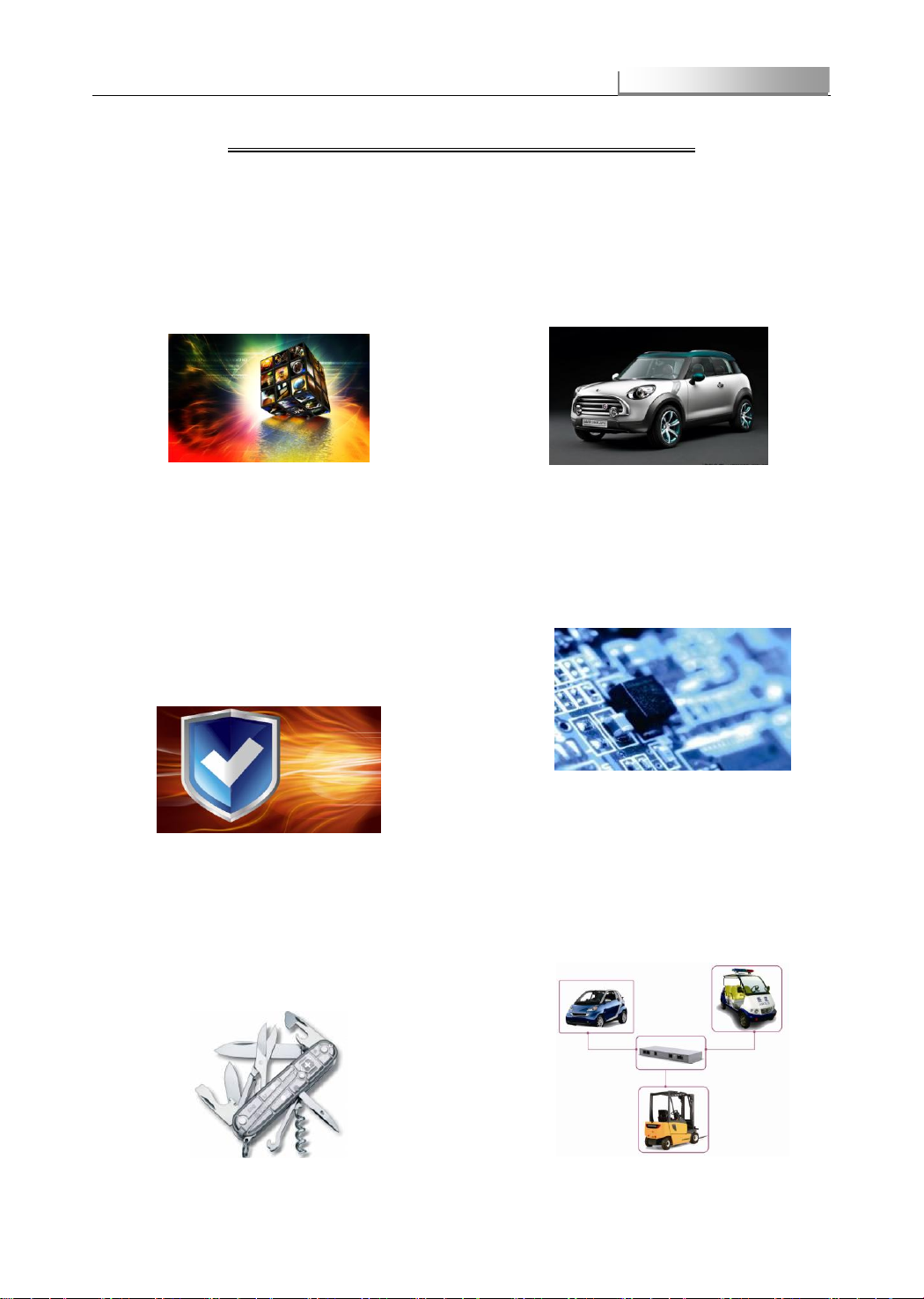
Prominent Advantages of EK-YT-21BMS
Power Function
System integration of voltage, current, temperature
and other battery information collection functions,
integrated SOC estimation, battery balance, data
storage and other ancillary functions, support CAN
Bus, 485 Bus communication, relay control, stem
node control and other management features,
function is powerful
High Reliability
Adopting multiple power isolation plans in order to
greatly increase reliability of the system sampling and
communication; high redundancy design of circuit
enhance the stability of system; unique balance
failure protection to ensure the balance function in
stable state; protection circuit design for each of the
power supply output interface, effectively improve
fault tolerance of the system; passed EMC test,
insulation resistance, pressure-proof, high and low
temperature aging, waterproof, dustproof and
vibration experiment to ensure the system is in
reliable operation.
Easy Installation
Unique integration design of detection and
management integrates the collection system and
control function in one module, only 4 interfaces
achieve a variety of collection, detection,
communication and control functions, greatly reduces
the complexity of system connection, improves
efficiency of the product installation, commissioning
and maintenance convenience.
Small Volume
Highly integrated automotive control chip, small
volume and excellent performance of automotive
components, realize three-dimensional narrowing of
length, width and height, greatly improve the product
adaptability to various models and equipment
High Accuracy
Adopting unique SOC estimation algorithm of battery
capacity-- Vmin-EKF algorithm (theory) estimation
accuracy is over 97%,being the first in this industry;
based on unique D–filter algorithm with high
accuracy collection system; system parameters
(dynamic battery voltage, current, etc) collection
errors are higher than this industry
Widely Application
High reliability, small volume, powerful function and
other features make the system can be widely
applied to various electric vehicles ( such as electric
motorcycle, light cars, mini-cars and the space
vehicles ), special vehicle and communication base
station BMS, especially suitable for a variety of small
volume, small capacity battery system.

EK-YT-21 BMS
- 2 -
Typical Application
Typical Application of EK-YT-21 BMS
EK-YT-21 BMS can be widely used in a variety of less than 24 strings of battery system, from electric vehicles battery to
emergency power supply of communication base station, meet different customers' various requirements in a full range.
Application in Electronic Vehicle
BMS plays a very important part in the whole electric control system of the electronic vehicle. BMS manages the whole
system in a safe, reliable and high efficient way by communicating with MCU and intelligent charger.
Technical Features:
Strong communication function: Communicate with MCU and intelligent charger via CAN-Bus or RS485 to insure the
efficient of the vehicle. Communicate with monitor via RS485 to show real-time parameters of the vehicle;
Perfect system control : BMS set up a perfect system control strategy, the alarm and the corresponding control signals
would be sent out timely and accurately when the overcharge, under voltage, over discharge, over-current, over-heat
occurs ; including sound and light alarm, CAN communication, switch signal and the relay control.
Powerful environmental adaptability: the system through EMC testing, high and low temperature aging, waterproof and
dustproof, vibration and other simulation experiment, can be adapted to the actual use of electric transport processes in a
variety of harsh environment, ensure the reliable operation of system;
别说明)
Pic 1 Electric Transport System (uncertain)

EK-YT-21 BMS
- 3 -
Typical Application
The Application of Communication Base Station
Although communication base station environment is relatively stable, its working state need asks for an extremely stable
system if keeping working. Only more stable, more reliable management system can effectively ensure power supply to the
communication base station.
Technical Features:
Powerful Protection Function: Overcharge protection, under voltage protection, over discharge protection, over heat
protection, over current protection etc, and reasonable logical control, provide powerful protection for equipment
continuous and stable operation
The comprehensive early warning: LCD screen sound alarm, LCD screen icon warning, buzzer alarm management
system and other sound and light warning mode, improve the system of early warning ability, facilitate a timely processing
to equipment
Storage and analysis of data: Optional DSM to achieve real-time record and save every key data, then analyze and
reconstruct all the data to establish a best mode of charge and discharge;
Pic 2 Communication Base Station System

EK-YT-21 BMS
- 5 -
Security Guide
Security Guide
Security warning explanation:
Hazards: Hazards that may cause fire or serious personal injury or death due to the failure of following required
operations.
Attention: danger that maycause a slight or moderate injury or damage to the system due to the failure of following
required operations.
Please read this part carefully during installation, adjustment or repairing. The user must follow the security instructions of
this part. In case of any damage or loss caused by any irregularities, the manufacturer party won't take any responsibility for
the damage or loss.
Usage
Hazards
This series of BMS must be specified voltage of power supply, or the system will get damaged.
This series of BMS is applied for monitoring and management of battery pack. It can't be used for other
application, or it will cause system failure or fire.
Inspection of the
goods' arrival
Attention
If it is found the BMS is damaged or any parts are missing, don't install it .or accident may occur.
When the goods you receive doesn't match the Pack list ,please contact sales person soon before
installation.(see Part Eight of this manual: Service Direction)
Installation
Attention
Handling with care during moving, installation to avoid damage of the product or injury to the person.
Keep away from inflammable items and heats.
Never let debris come into the BMS, otherwise it will lead to system failure.
The shell of Insulation Test Module must have good connection with the body of the vehicles, or the module will
be ineffective.
Wiring
Hazards
Wiring should be operated by qualified electrical engineers. Otherwise, there will be risk of electric shock or
damaging the system.
Before wiring, make sure the power supply is cut off or it has risks of electric shock or fire.
Attention
Strictly follow the sequence of the address of the Data Collection Module during installation, or the data that
DCM has collected won't match with the data that the screen displays.
Make sure if the serial number of DCM is the same with the battery serial number, otherwise it leads to
incomplete data collection.
Make sure the sequence of wiring of voltage monitoring cables is right or not, or it will damage the system
Check the wiring of relay is correct or not, or it will cause system failure or battery pack damage.
Check the wiring of positive pole and negative pole of the power supply is correct or not, or it will cause system
failure.
Operation
Hazards
After all the modules and wirings are correctly connected, power on the system.
The parameter on the screen can't be changed at ease, or it might damage the battery pack.
Attention
Before running, make sure this system is used within the allowed conditions and applications, or it might cause
system failure.
Before running, make sure the control strategy is correct or not, or it might cause damage to the battery pack.
Maintenance And
check
Hazards
Cut off the power supply before removing the shell to avoid the risks of electric shock
Circuit board has a lot of chips. Don't touch it to prevent electrostatic damage to the circuit board.
Specify qualified electrical engineers for maintenance, inspection or replacement of parts.
Other
Hazards
Prohibit self-transformation of this system to avoid any serious accident.

EK-YT-21 BMS
- 6 -
Catalogue
Catalogue
Chapter 1 Introduction of EK-YT-21 Battery Management System................................................................... - 8 -
1.1 System Structure.................................................................................................................................- 8 -
1.2 System Configuration.........................................................................................................................- 8 -
1.3 Function of System.............................................................................................................................- 9 -
1.4 Technical Parameters.........................................................................................................................- 9 -
Chapter 2 EK-YT-M2124 Module in EK-YT-21 BMS......................................................................................... - 10 -
2.1 Function of EK-YT-M2124................................................................................................................- 10 -
2.2 Model of EK-YT-M2124 Module...................................................................................................... - 11 -
2.3 EK-YT-M2124 Module Basic Protection Parameters................................................................... - 11 -
2.4 EK-YT-M2124 Module Installation Size.......................................................................................... - 12 -
2.5 EK-YT-M2124 Module Interface......................................................................................................- 12 -
Chapter 3 Monitor on EK-YT-21 BMS ............................................................................................................ - 15 -
3.1 Screen Function ................................................................................................................................ - 15 -
3.2 Screen Selection...............................................................................................................................- 15 -
3.3 Screen Shape Size...........................................................................................................................- 16 -
3.4 Screen Interface................................................................................................................................- 17 -
3.5 Main Interface of Screen..................................................................................................................- 18 -
3.6 Display Configuration Parameter....................................................................................................- 18 -
3.7 Display Screen Parameter Configuration ......................................................................................- 19 -
3.8 Battery Cell Information Display......................................................................................................- 20 -
3.9 Charger Information Display............................................................................................................ - 21 -
3.10 Instruction of Charging Control .....................................................................................................- 21 -
Chapter 4 Current Sensor On EK-YT-21 BMS................................................................................................ - 23 -
4.1 Current Sensor Function..................................................................................................................- 23 -
4.2 Current Sensor Selection.................................................................................................................- 23 -
4.3 Current Sensor Size..........................................................................................................................- 24 -
4.4 Current Sensor Interface..................................................................................................................- 24 -
Chapter 5 Installation of EK-YT-21 BMS....................................................................................................... - 25 -
5.1 System Wiring Diagram....................................................................................................................- 25 -
5.2 Installation Environment and Requirement....................................................................................- 25 -
Chapter 6 System wiring for EK-YT-21 BMS....................................................................................................- 26 -
6.1 Type of Cables...................................................................................................................................- 26 -
6.2 Cables.................................................................................................................................................- 26 -
6.3 Cable Connect Mode........................................................................................................................- 28 -
Chapter 7 Malfunction Handling .................................................................................................................. - 32 -
7.1 Malfunction and Prompts .................................................................................................................- 32 -
7.2 Procedures of Diagnosis of Malfunction. ....................................................................................... - 34 -
Chapter 8 Regular Maintenance ................................................................................................................... - 35 -
Chapter 9 Service Direction.......................................................................................................................... - 36 -

EK-YT-21 BMS
- 7 -
Catalogue
9.1 Contact Information...........................................................................................................................- 36 -
Appendix A System List ..............................................................................................................................- 37 -
Appendix B Product Certificate ................................................................................................................. - 38 -
EK-YT-21 BMS
- 8 -
Introduction
Chapter 1 Introduction of EK-YT-21 Battery Management System
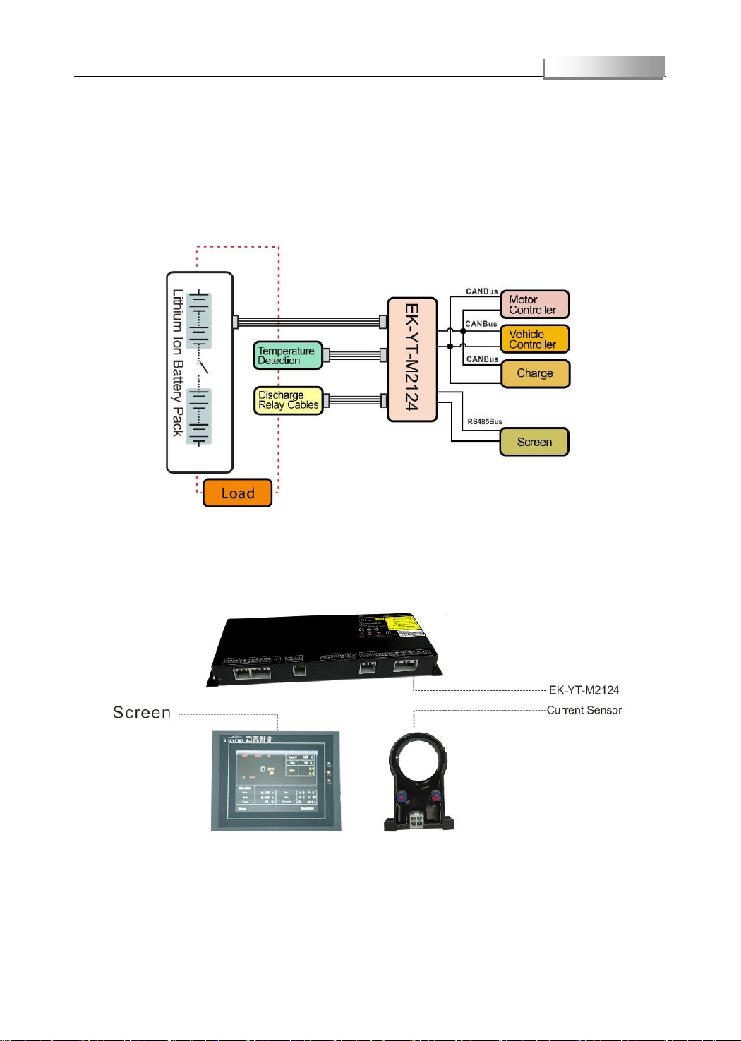
1.1 System Structure
EK-YT-21 BMS is composed of EK-YT-M2124 module which has functions of system management and information
monitoring, monitor(optional), current sensor and cables.
Pic 1-1 System Structure
1.2 System Configuration
Pic 1-2 System Configuration

EK-YT-21 BMS
- 9 -
EK-YT-M2124
1.3 Function of System
The EK-YT-21 system adopts the design of detection and management in collection , with high precision, high accuracy
function of information collection, can collect voltage of single cell, battery voltage, battery box temperature and other data,
balance single cell ,analyze and processing the battery pack data; send alarm and control according to the battery status
The EK-YT-21 system through the current sensor to collect current data, determine the charging and discharging state,
complete working current measurement, charge and discharge control of the battery pack, comprehensive utilization of the
battery data to do SOC estimation and discrete evaluation.
The EK-YT-21 system can also real-time display the battery pack voltage, current, temperature, SOC etc. and convenient
setting by screen.
1.4 Technical Parameters
Table 1-1 Technical Parameters of BMS
Specification
Remarks
System Power Supply
DC12V/DC24
DC9~16V/DC16~32V
System Power
≤3W
Not Including Screen and other accessories.
Accuracy of Monomer Voltage Detection
±10mV
0~4.7V
Current Accuracy
±1%
±500A
±0.3A
≤30A
SOC Accuracy in theory
≥97%
Accuracy of Temperature Detection
±1℃
-40℃~85℃
±2℃
85~125℃
Rated Current of Relay
≤1A
Peak≤2A
Rated Current of Switching Signal
≤1A
Working Temperature Range
-20℃~70℃
Storage Temperature Range
-40℃~85℃
Balance Current
250mA/Circuit at most
Working Moisture Range
40%~90%
Anti-electromagnetic Interference Range
400MHZ~1000MHZ
Note)* Voltage of single cell only take Lithium iron phosphate battery for example, other types of batteries can be
customized based on customer requirements
Introduction

EK-YT-21 BMS
- 10 -
EK-YT-M2124
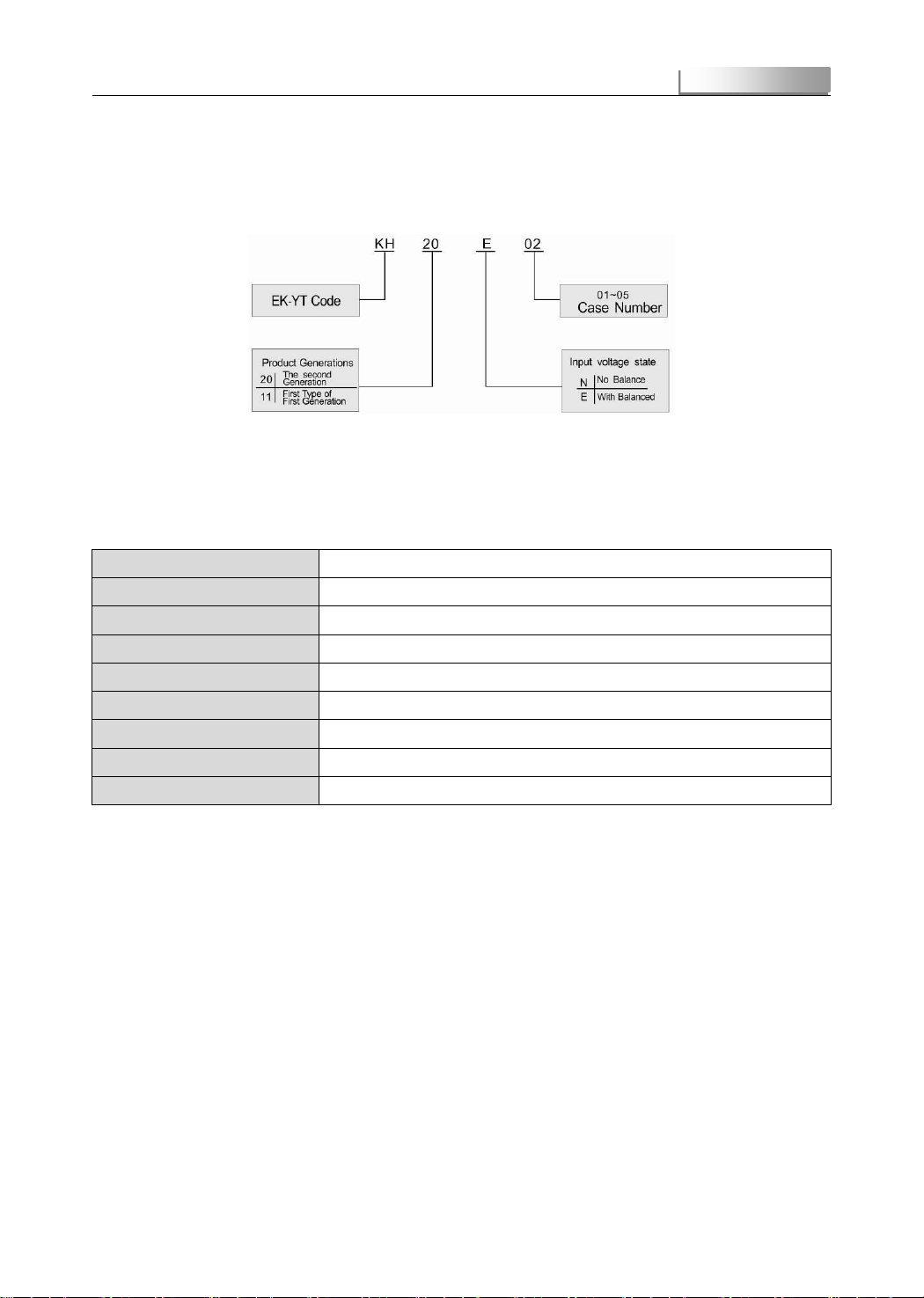
1.5 Product Code
B00010 Y4 016 E110320001
Production code
Type of balance
Total number of series
Type of system code
Custom code
Pic 1-3 Product System Code
Chapter 2 EK-YT-M2124 Module in EK-YT-21 BMS
2.1 Function of EK-YT-M2124
EK-YT-M2124 is the core equipment in EK-YT-21 for collect, process and control of system data. The main functions are
as follow:
Information Collecting Function
Max.24 of single cell voltage real time high precision data collection and wave filtering processing
Max. 4 of real time acquisition and processing to temperature sensor signal
Collection and processing to charging and discharging current
Communication and Control Mode
1 CAN-bus communication
1 communication mode of display screen LCD_485
1 RS485 communication mode to realize customers’requirement
2 relay control modes (charge and discharge)
2 switch signal control modes
Battery equilibrium strategies
The battery voltage real-time detection of consistency
The 250mA charging balance
The balanced failure protection function
System Management Function
SOC high precision estimation
The battery failure alarm
EK-YT-21 BMS
- 11 -
EK-YT-M2124
Real time processing and distribution of battery pack and system information
2.2 Model of EK-YT-M2124 Module
Pic 2-1 EK-YT-M2124 Module Mode
2.3 EK-YT-M2124 Module Basic Protection Parameters
Table 2-1 EK-YT-M2124 Module basic protection parameters (uncertain)
Name
Value
Overcharging protection voltage
3.70V
Overcharging release voltage
3.60V
Under Voltage alarm voltage
3.15V
Under Voltage release voltage
3.20V
Over discharging protection voltage
2.60V
Over discharging release voltage
2.8V
Over heat protection temperature
55℃
Over heat release temperature
40℃
Note)* The above parameters are basic protection parameters, they can be configured according to customer demand.
EK-YT-21 BMS
- 12 -
EK-YT-M2124
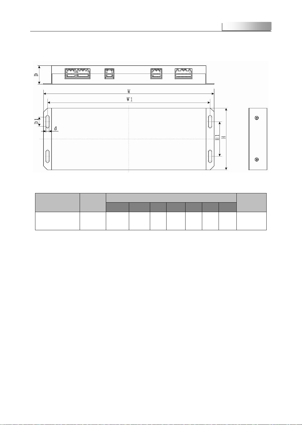
2.4 EK-YT-M2124 Module Installation Size
Pic 2-2 EK-YT-M2124 Module Installation Size Diagram
Table 2-2 Size of EK-YT-M2124 Module
Product Name
Product
Model
Shape and Installation Size
(
Unit
:
mm
)
Weight(KG)
W
H
D
W1
H1
D1
d
EK-YT-M2124
Module
KH20E02
296
107
31
283
60
12
4.5
0.89
Note)* W, H, D as the external structure size, W1, H1, D1 as the installation size of internal structure , D is width of
installation hole
2.5 EK-YT-M2124 Module Interface
2.5.1 EK-YT-M2124 Module Interface Distribution

EK-YT-21 BMS
- 13 -
EK-YT-M2124
Pic 2-3 EK-YT-M2124 Module Interface Distribution Picture
2.5.2 EK-YT-M2124 Module Interface Function
Table 2-3 EK-YT-M2124 Module Interface Function
Interface
Number
Interface Name
Interface Function
1
Voltage Detection Interface
Fulfill the voltage detection of a single battery
2
Temperature Detection Interface
Real time monitor of battery temperature
3
System Power and Current Sensor Interface
Supply the working voltage of EK-YT
Connect to current sensor to monitor real time working current.
Output control of discharge relay
4
Communication Interface
LCD display power output
LCD display 485-bus
CAN-bus to communicate with vehicle control system
CAN-bus to communicate with charge
485 to communicate with optional DSM

EK-YT-21 BMS
- 14 -
EK-YT-M2124
Reserve 2 switching signal control circuit to meet customer specified
Control charge relay
2.5.3 EK-YT-M2124 Module Interface Define
Table 2-4 EK-YT-M2124 Module Interface Define
接
口
Interface Exterior
Interface Line Order Define
1
1
2
3
……
25
26/27/28
B1+
B1-
B2-
……
B24-
空
2
1
3
5
7
2、4、6、8
Temperature Sensor
Signal 1
Temperature Sensor
Signal 2
Temperature Sensor
Signal 3
Temperature Sensor
Signal 4
GND
3
1
2
3
4
5
6
7
8
9、10、11、12
Discharge
Relay
Control+
Discharg
e Relay
Control-
System
Power
Input+
System
Power
Input-
Current
Sensor
Power
Output+
Current
Sensor
Power
Output -
Current
Sensor
Signal
Input
GND
空
4
1
2
3
4
5
LCD Power
Output+
LCD Power
Output-
LCD RS485+
LCD RS485-
GND
6
7
8
9
10
GND
RS485+
RS485-
GND
GND
11
12
13
14
15
CAN_H
CAN_L
CAN_H
CAN_L
External
Switching Signal
Control 1+
16
17
18
19
20
External Switching
Signal Control 1-
External Switching
Signal Control 2+
External Switching
Signal Control 2-
Charge Relay Control
+
Charge Relay
Control -
EK-YT-21 BMS
- 15 -
EK-YT-M2124
Chapter 3 Screen on EK-YT-21 BMS
3.1 Screen Function
Screen is the User Interface of system running situation. All types are all designs by industry standard and suitable to
various environments. The display interface of screen can display all kinds of operation parameters of the system and fault
condition.
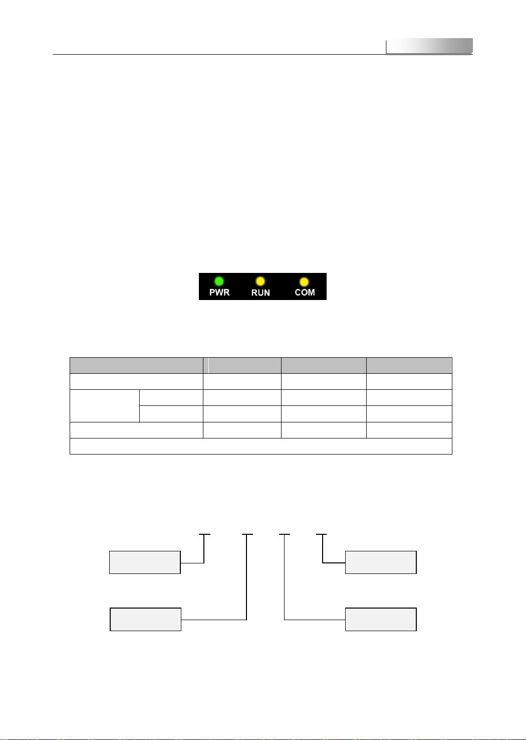
Description:
There are three lights on the screen that indicate the status of the operation of the system, including power light (PWR),
Running (RUN), communication (COM). When the screen is powered on, the PWR light will be always bright; if the RUN light
is always bright, it means the screen is running fine; if the RUN light is dark, it means the screen has something wrong; if the
EMS is connected, COM light is flash yellow.
Pic 3-1 Indicator Light in Operation Status
The following table shows indicator lights status in different state:
Table 3-1 Pilot Lamp Condition on Screen
Equipment Status
Green LED(PWR)
Yellow LED(RUN)
Yellow LED(COM)
No Power
○
○
○
Power on and no
communication
3.5 Inch Screen
●
●
●
5.7 Inch Screen
●
●
○
Communicate with equipment
●
●
※
○ LED Off ● LED On ※Flicker
3.2 Screen Selection
Pic 3-2 Screen Model
Screen Number
Screen Code
KX 01 00 01
Spare Code
Manufacturer Code
Screen
EK-YT-21 BMS
- 16 -
EK-YT-M2124
Table 3-2 Screen Selection Table
Product Name
Screen Model
3.5 Inch Screen
KX010001
5.7 Inch Screen
KX010002
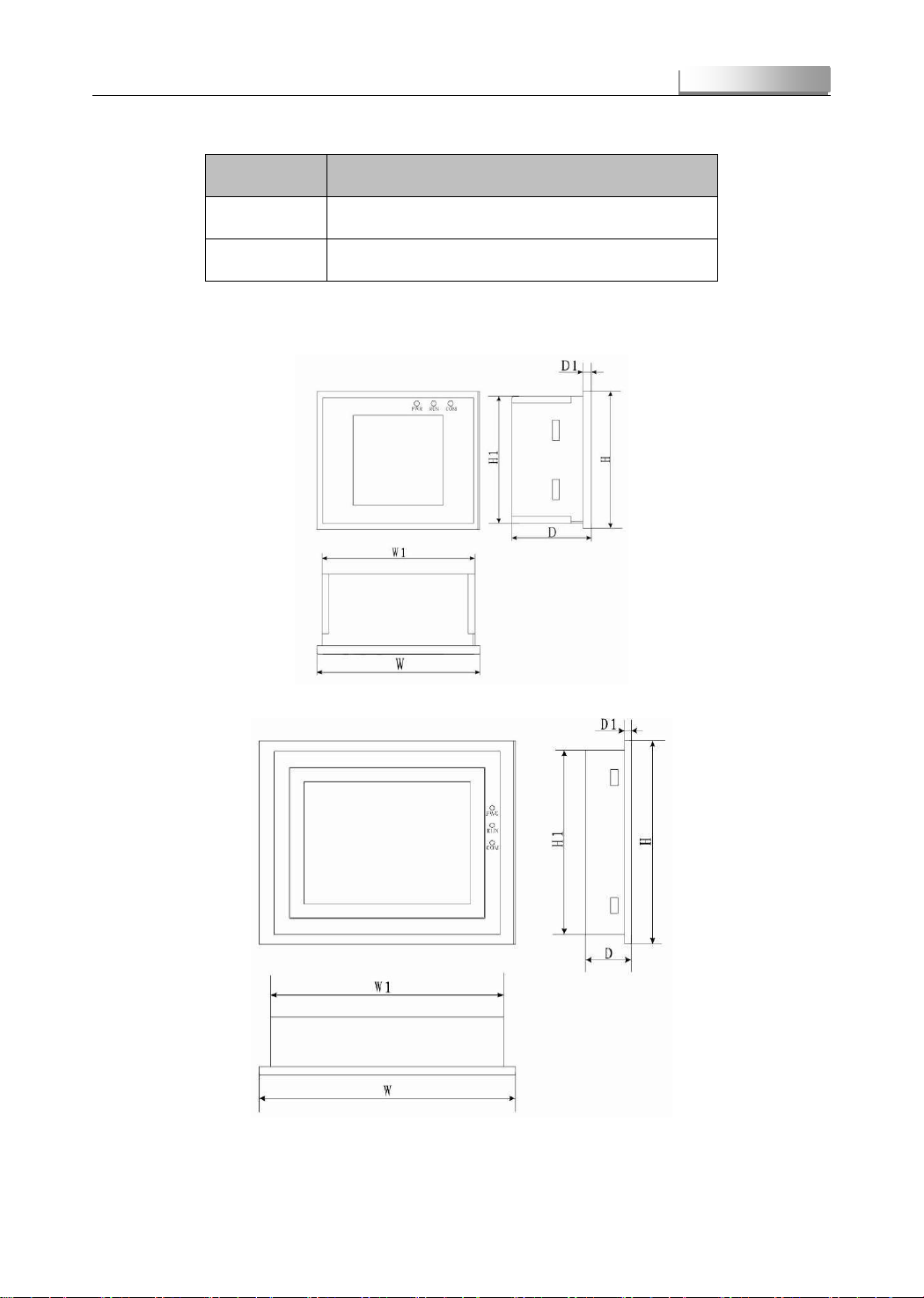
3.3 Screen Shape Size
Pic 3-3 3.5 Inch Screen Size
Pic 3-4 5.7 Inch Screen Size
Screen
EK-YT-21 BMS
- 17 -
EK-YT-M2124
Table 3-3 Screen Size
Product Name
Product
Type
Shape and Installation Size
(
Unit
:
mm
)
Weight(KG)
W
H
D
W1
H1
D1
d
3.5 Inch Screen
KX010001
96
81
46
90
73
4
4
0.186
5.7 Inch Screen
KX010002
177
140
40
161
130
6
4
0.5
Note)* W, H, D as the external structure size, W1, H1, D1 as the installation size of internal structure , d is width of
installation hole
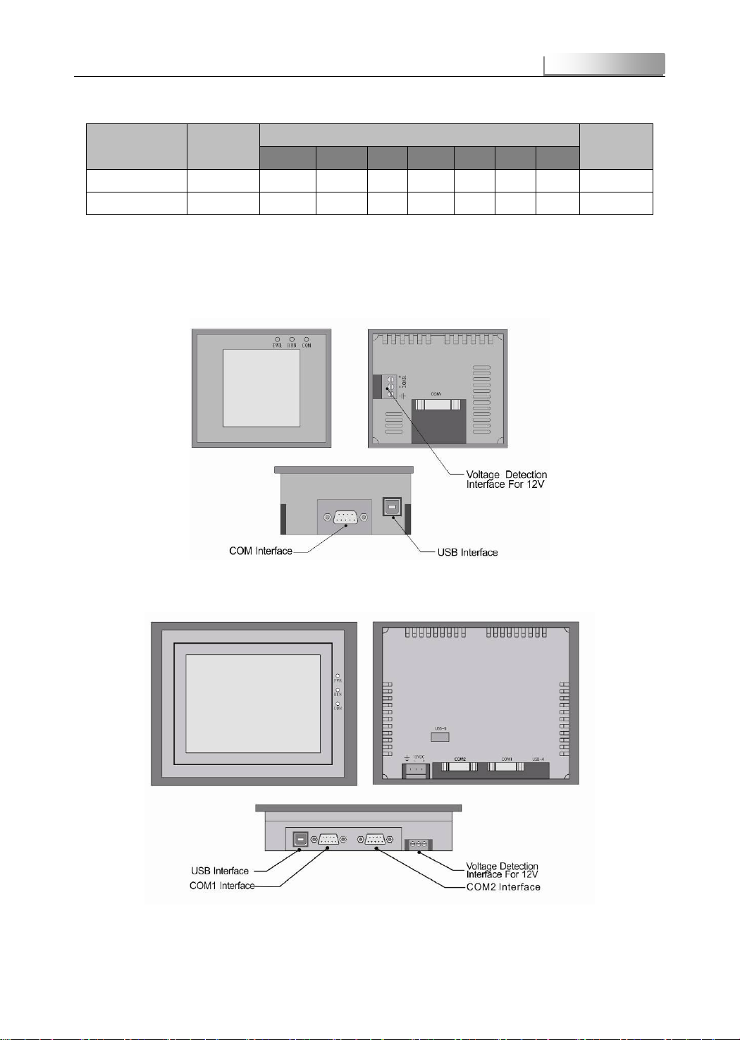
3.4 Screen Interface
Pic 3-5 3.5 Inch Screen Interface
Pic 3-6 5.7 Inch Screen Interface
Screen

EK-YT-21 BMS
- 18 -
EK-YT-M2124
3.5 Main Interface of Screen
When screen is working with system power, the main interface of screen will be as the following picture:
Pic 3-7 Screen Main Interface
Note)*1. The above 、 、 、 、 icon only displayed in failure state and not display in nornal
condition.
* 2 Both 1-30 seconds delay for all the protection and release
* 3 Display screen may change, please take the actual one as true.
3.6 Display Configuration Parameter
Total Capacity
Battery releases the maximum capacity when it completes charging. Generally batteries’ nominal capacity would be
used for initial configuration.
Remain Capacity
Current ampere value of battery, it is configured according to the parameters provided by the manufacturer.
Calibration of Current
Used for current zero point correction, current calibration values is 0.0A in default condition, if the system stops running
(no charge or discharge), the screen shows current is not 0, ―, the current can be calibrated to 0Aby setting the" Current
Cal. Calibration range from - 20.0A to 20.0A. For example: the screen shows current values for 0.6A when the system
Screen

EK-YT-21 BMS
- 19 -
EK-YT-M2124
stops," Current Cal by typing" 0.6A, and click the" Settings", current can be calibrated to 0Aby inputting 0.6Afor Current
Cal and click "setting".
Calibration of Voltage
Used for zero correction of voltage value, the calibration value of voltage is 000mV in default condition
Max Current of Charging
Defines CAN communication charger allowed maximum charging current.
Overcharging Protection Voltage
Defines the highest allowed rising voltage value during charging process of single cell, above this value it needs to
perform overcharging protection and alarm to the battery.
Overcharging Release Voltage
Canceling the protection voltage threshold, of overcharging i.e. when the max voltages value of single cell below this
value it cancels the overcharging protection and alarm.
Under voltage Protection Voltage
Define low voltage alarm threshold of single cell, for prompting the battery is not much.
Under voltage Release Voltage
Cancelling alarm voltage threshold when under voltage i.e. under voltage alarm is cancelled when the lowest voltage of
single voltage is higher than the parameter.
Over discharging Protection Voltage
Definition of lowest voltage allowed falling when battery discharges, discharge protection occurs when below this value.
Over discharging Release Voltage
Defines cancelling parameters of over discharging protection, i.e. when the lowest voltage is higher than the parameter
of single cell, it will cancel over discharging protection to battery
Over Heat Protection Threshold
Definition of battery maximum allowable working temperature, over-temperature protection and alarm to battery occurs
when higher than the temperature.
Over Heat Release Threshold
Definition of overheat alarm release temperature threshold, i.e. it cancels over-temperature protection and alarm when
the highest temperature of the battery is lower than this value.
3.7 Display Screen Parameter Configuration
In order to accurately estimate all parameters of batteries, BMS can be re-configured for the first time of running.
The parameters that can be reset includes: total capacity of the battery pack (nominalcapacity), SOC, current calibration,
over charge voltage of single cell, over charge release voltage of single cell, under-voltage protection voltage for single
cell, under-voltage release voltage for single cell, over discharge protection voltage, over discharge release voltage for
single cell, over heat protection temperature, overheat release temperature.
Step 1 Click the button ―Apply‖ and then input the password ―8888‖ to enter BMS configuration page.
Screen
Table of contents
Popular Automobile Accessories manuals by other brands


Slee
Slee MaxTrax SOK0054 Installation instruction

DECKED
DECKED DS1 installation instructions

Mont Blanc
Mont Blanc MB RoofBar ReadyFit RF 28 Fitting instructions

ULTIMATE SPEED
ULTIMATE SPEED 106321 Assembly and Safety Advice

Sony Ericsson
Sony Ericsson HBM-30 Disclaimer and safety guidelines

Panasonic
Panasonic CF-WEB184 Series operating instructions


