Racelogic PerformanceBox User manual

Racelogic Ltd Introduction
02/05/2014 Page 1
CONGRATULATIONS ON PURCHASING A RACELOGIC PERFORMANCEBOX!
PerformanceBox is based on the Racelogic VBOX, which is used by the majority of Car
Manufacturers, Tyre Manufacturers and car magazines around the world to assess performance.
You can be sure that in PerformanceBox you have a product which will prove to be invaluable in all
your motorsport applications.
Performance
With PerformanceBox it is very easy to measure acceleration
times, braking distances, quarter mile times and many more.
There are a number of configurable screens that show specific
test results such as 0-60, 0-100, 0-100-0, ½ mile and ¼ mile
etc.
Because it is very easy to edit the test ranges,
PerformanceBox is a very powerful tool for use in many
different kinds of vehicle testing. Vehicle modification can be
readily assessed and given specific improvement parameters
–the perfect tool for any tuning enthusiast.
Because it is very easy to edit the test ranges,
PerformanceBox is a very powerful tool for use in many
different kinds of vehicle testing.

Racelogic Ltd Introduction
02/05/2014 Page 2
Lap Timing
Displaying your Lap times as you drive around a circuit is simple with PerformanceBox. You can
display your last and best Lap times and Lap count, and also display split times for up to six
specified split points around the lap. The split files can be saved and reused should you attend the
same circuit again, guaranteeing consistent data. You will be able to catalogue and review your
performance over any given period of time.
Through the PerformanceBox website and forum you are able to download circuit overlays from
around the world, compare lap times, and share lap overlay data with other users.
Speed Display
PerformanceBox has a display screen mode that shows a large digital speed value and compass.
In open conditions, PerformanceBox has a velocity accuracy of 0.1km/h, which is useful for
checking the accuracy of your vehicle’s speedometer.
In this mode there are also Odometer and Height display screens.

Racelogic Ltd Introduction
02/05/2014 Page 3
Power Calculations
PerformanceBox can help you to measure the power developed by your car’s engine, either at the
wheels or flywheel. Having set the vehicle weight, results are calculated from the measurements
taken by the fast GPS engine to give you useful guidelines to the car’s brake horsepower or
kilowatt output. Because these calculations are made from the GPS data rather than
accelerometers, your results are likely to be more consistent and accurate.
Data Logger
For drivers keen to improve their lap times and get valuable feedback on technique,
PerformanceBox includes a sophisticated, fully functioning data logging package. If used with a
64mb SD card, PerformanceBox can log up to 50 hours of continuous data, which can be analysed
in great detail in the available software.
This software allows graphical analysis of acceleration, braking, cornering and lap times, and if the
PerformanceBox is used in conjunction with a Micro Input Module, data from the vehicle itself
(such as RPM and throttle angle) is recorded alongside the GPS parameters.
You can overlay up to four files, and you get an accurate track map to compare your driving line
between different laps. The software also features a graph measure tool, allowing for precise
analysis of performance figures. Data-logging capabilities are further enhanced by automatically
generated text data on the SD card.

Racelogic Ltd Contents
02/05/2014 Page 4
Contents
QUICK START GUIDE.....................................................................................................................7
INTRODUCTION .............................................................................................................................7
FEATURES ....................................................................................................................................7
Optional Accessories / Replacement Parts..............................................................................7
CONNECTIONS..............................................................................................................................8
MOUNTING PERFORMANCEBOX IN YOUR CAR .................................................................................8
REGISTERING YOUR PERFORMANCEBOX AND ACTIVATING ALL AVAILABLE FUNCTIONS.......................8
Registering Your PerformanceBox..........................................................................................8
ACTIVATING THE ADDITIONAL FUNCTIONS IN YOUR PERFORMANCEBOX ............................................9
USING PERFORMANCEBOX......................................................................................................10
PERFORMANCEBOX KEYPAD .......................................................................................................10
CHANGING MODES......................................................................................................................10
CHANGING THE UNITS OF MEASUREMENT ....................................................................................11
SATELLITE RECEPTION................................................................................................................11
Searching for satellites at power up.......................................................................................11
PERFORMANCE MODE..............................................................................................................12
MEASURING THE 0-60 TIME OF YOUR VEHICLE ..............................................................................13
EDITING A PERFORMANCE MODE TEST RANGE .............................................................................14
1FOOT ROLLOUT .......................................................................................................................15
RESULTS AND BEST FILES...........................................................................................................15
Example RESULTXX.TXT file:..............................................................................................16
Example BESTXX.TXT file:...................................................................................................16
SPEED BUZZER...........................................................................................................................17
EVENT MARKING.........................................................................................................................17
LAPTIMING MODE ......................................................................................................................18
MEASURING LAP TIMES ...............................................................................................................18
Simple Lap Timing ................................................................................................................18
Lap Count .............................................................................................................................19
Lap Timing Including Split Points...........................................................................................19
Big Speed @ Split display.....................................................................................................19
Split to Split time ...................................................................................................................20
Split Widths...........................................................................................................................20
Clearing your Best Lap time..................................................................................................20
ONE SHOT MODE........................................................................................................................20
START /FINISH AND SPLIT LINES...................................................................................................21
Setting start / finish lines .......................................................................................................21
Saving start / finish and Split Lines........................................................................................22
Loading start / finish and split Lines.......................................................................................22
Clearing start / finish and split Lines......................................................................................22
RECORDING AND REVIEWING LAP AND SPLIT TIMES......................................................................22
PREDICTIVE MODE.....................................................................................................................24
FIXED LAP..................................................................................................................................25
SPEED DISPLAY MODE..............................................................................................................26
ODOMETER ................................................................................................................................26
ALTIMETER.................................................................................................................................26
EVENT MARKING.........................................................................................................................26
POWER TESTING ........................................................................................................................27
Setting the Vehicle Weight ....................................................................................................27
Power Runs ..........................................................................................................................28

Racelogic Ltd Contents
02/05/2014 Page 5
CALCULATING LOSSES ................................................................................................................28
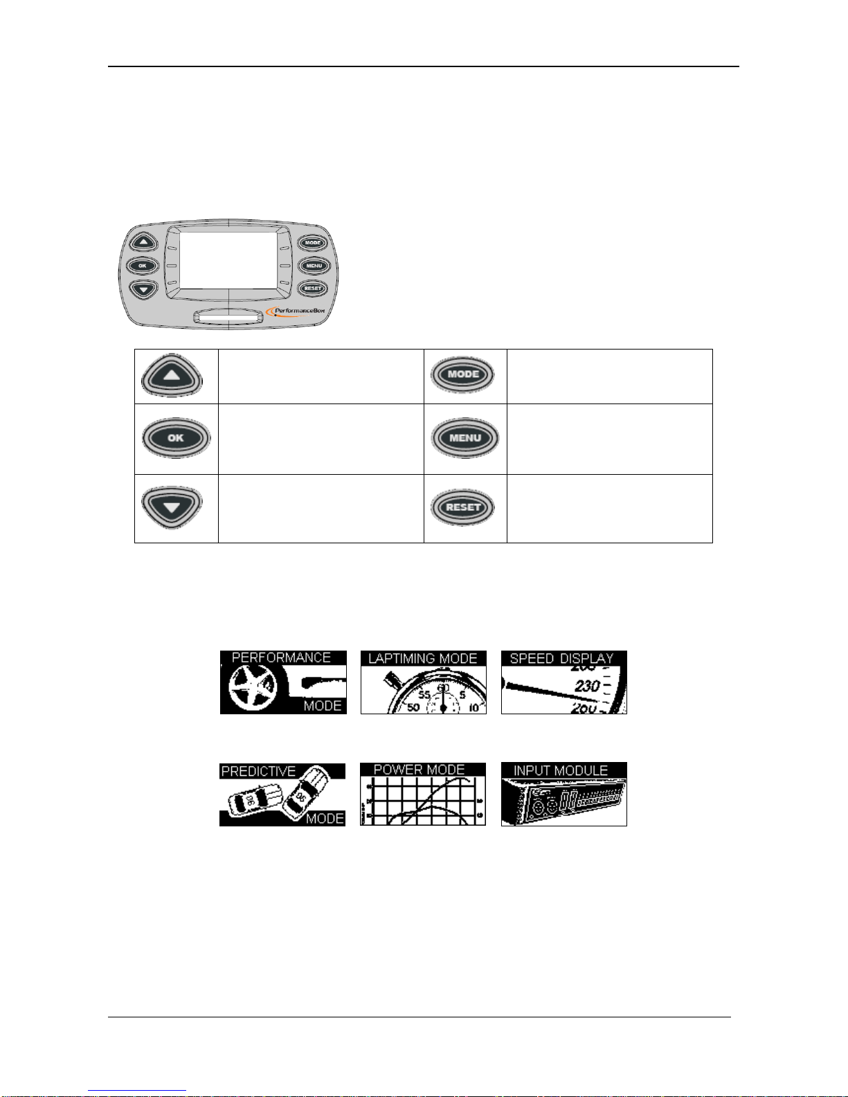
INPUT MODULE SCREEN...........................................................................................................30
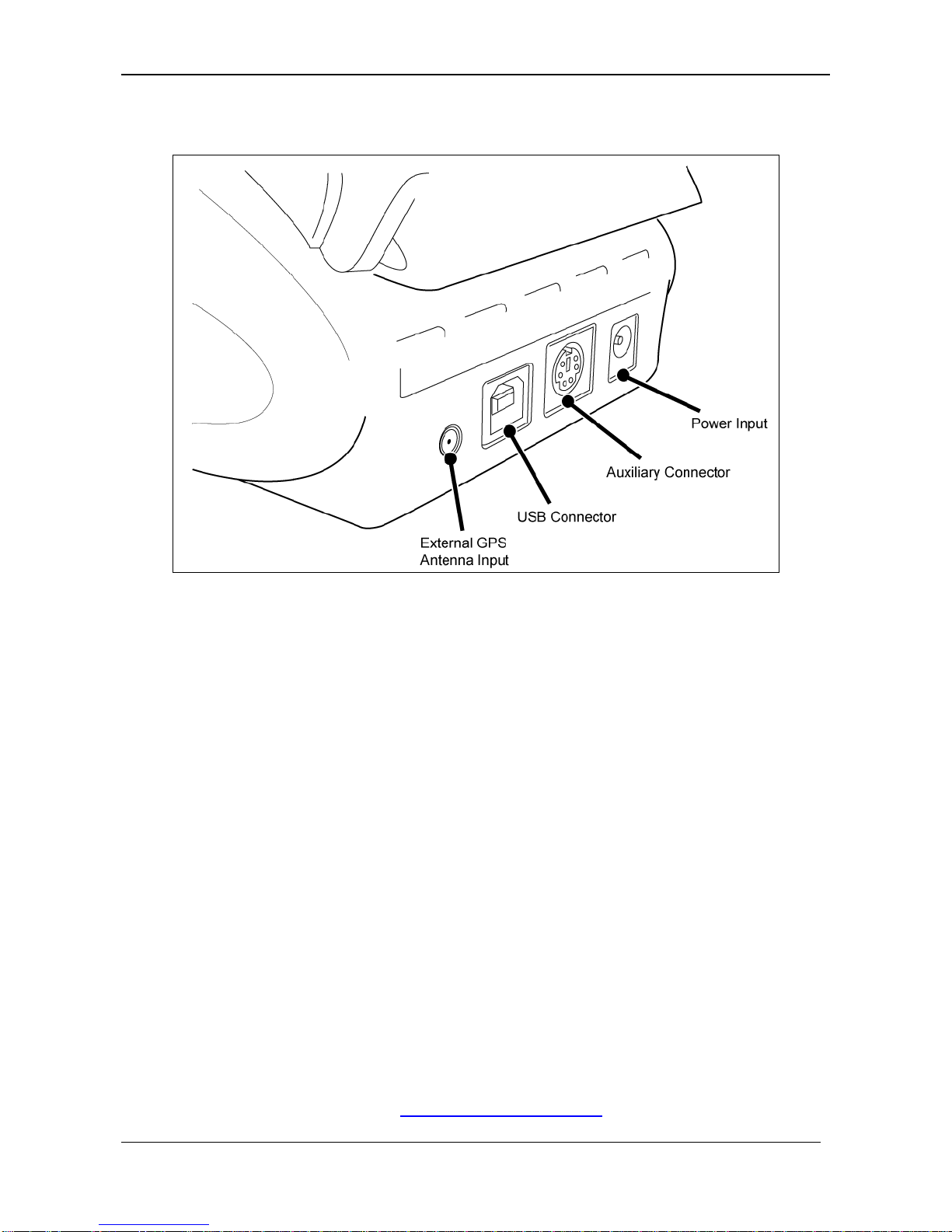
INPUT MODULE CONNECTION .......................................................................................................30
INITIALISING THE MICRO INPUT MODULE. ......................................................................................30
CONFIGURING THE INPUTS AND OUTPUTS ....................................................................................30
DATA LOGGING..........................................................................................................................31
USING THE SD CARD...................................................................................................................31
FILE TYPES.................................................................................................................................31
SETUP MENU ..............................................................................................................................32
LOGGING MODE..........................................................................................................................32
CONTRAST &BRIGHTNESS..........................................................................................................32
DIAGNOSTIC SCREENS................................................................................................................32
GPS Diagnostic Screen.........................................................................................................32
COLD START ..............................................................................................................................33
Performing a Coldstart ..........................................................................................................33
SPEED BUZZER...........................................................................................................................33
TROUBLESHOOTING..................................................................................................................34
PERFORMANCETOOLS SOFTWARE ........................................................................................35
INSTALLATION.............................................................................................................................35
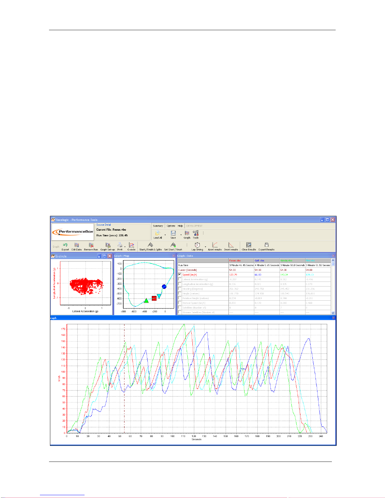
PERFORMANCETOOLS WINDOWS.................................................................................................35
Graph Window ......................................................................................................................36
Graph: Map Window..............................................................................................................36
Graph: Data Window.............................................................................................................36
Window Sizes and Positions .................................................................................................36
SOFTWARE BASICS.....................................................................................................................37
Opening PerformanceBox Files –Load All............................................................................37
Data Display..........................................................................................................................37
Graph Set-up.........................................................................................................................37
MOVING AROUND THE GRAPHS....................................................................................................38
Cursor...................................................................................................................................38
Zoom.....................................................................................................................................38
Pan .......................................................................................................................................38
Graph Screen X Axis.............................................................................................................38
Graph Screen Y Axis.............................................................................................................39
ADDITIONAL FILE FUNCTIONS ......................................................................................................39
Load Compare File................................................................................................................39
Append File to Main ..............................................................................................................39
Open in Notepad...................................................................................................................39
Load Circuit Map...................................................................................................................39
EDITING PERFORMANCEBOX FILES..............................................................................................39
SAVING PERFORMANCEBOX FILES...............................................................................................40
PRINTING GRAPH DATA...............................................................................................................40
EXPORTING GRAPH DATA............................................................................................................41
SELECTING CHANNELS................................................................................................................42
CHANNEL AND AXIS SETUP..........................................................................................................44
Channel Setup ......................................................................................................................44
Axis Setup.............................................................................................................................46
LAP TIMING ................................................................................................................................48
START /FINISH LINES AND SPLITS................................................................................................49
Defining start / finish lines and splits in the PerformanceBox software ..................................49
Loading and Saving start / finish line and split data...............................................................50
Clearing start / finish line and split data.................................................................................50
Moving Splits.........................................................................................................................50

Racelogic Ltd Contents
02/05/2014 Page 6
Show Split Info on Graph Chart.............................................................................................50
Gate Width............................................................................................................................50
Split Names...........................................................................................................................51
DISPLAYING LAP TIMES ...............................................................................................................51
Including Split times ..............................................................................................................51
Exporting Lap Time Results ..................................................................................................52
Clearing Lap Time Results....................................................................................................52
Lap Highlight.........................................................................................................................52
Loading and comparing individual laps from the same file.....................................................53
Loading and comparing individual laps from different files.....................................................55
Replaying Laps (DriftBox Tools Only)....................................................................................57
Set Position Cursor Type ......................................................................................................57
CREATING A CIRCUIT OVERLAY....................................................................................................59
Creating an Overlay File by Driving the Circuit......................................................................59
Creating an Overlay File in Google EarthTM...........................................................................59
Loading a Circuit Overlay File ...............................................................................................59
Aligning Circuit Overlays and Laps........................................................................................60
Importing a background image in to the Graph Map..............................................................62
Producing Acceleration Results.............................................................................................63
Creating a Custom Acceleration test.....................................................................................64
Producing Deceleration Results ............................................................................................64
Creating a Custom Deceleration test.....................................................................................64
ADDITIONAL DATA ANALYSIS FEATURES.......................................................................................65
THE G-CIRCLE............................................................................................................................65
GRAPH MEASURE TOOL ..............................................................................................................66
Creating a Measure Tool Window .........................................................................................66
Saving and Printing the Measure Tool Data Table ................................................................66
EVENT MARKING.........................................................................................................................67
TOOLS .......................................................................................................................................68
Arrange Windows..................................................................................................................68
Export Data...........................................................................................................................68
Formatting MMC/SD Cards...................................................................................................69
Import Data...........................................................................................................................69
File Repair.............................................................................................................................69
Radius of Turn set-up............................................................................................................70
OTHER FEATURES ......................................................................................................................70
Export Results.......................................................................................................................70
Summary...............................................................................................................................70
Units of Measurement...........................................................................................................70
Help ......................................................................................................................................70
FIRMWARE UPGRADES.............................................................................................................71
SPECIFICATION..........................................................................................................................72
CONTACT INFORMATION ..........................................................................................................72

Racelogic Ltd Quick Start Guide
02/05/2014 Page 7
Quick Start Guide
Introduction
PerformanceBox is a self-contained GPS data logger and Performance Meter. A 10Hz fully
calibrated GPS engine is used to provide accuracy and precision and the data can be stored on a
removable SD flash card. Real time results are displayed on the back-lit LCD display and a USB
connection allows data to be downloaded to a laptop for further in-depth analysis.
Features
Non-contact 10Hz speed and distance measurement using GPS
Internal GPS antenna
Back-lit LCD screen for viewing live data and results
Lateral and longitudinal g-force measurement
SD Card slot for use with SD Cards
USB interface for reading SD card and upgrading firmware
Full data-logging analysis software
Logging of one RPM channel and up to four analogue channels when used in conjunction
with optional Micro Input Module.
Optional Accessories / Replacement Parts
Description:
Racelogic Part Number:
SD Card (4 GB)
RLACS098
External GPS Antenna
RLACS070-R
Mains Power Supply (UK / EU / US / JP
/ AU)
RLACS074-UK / -EU /-US / -JP / -AU
Windscreen Mount
RLACS071
Windscreen Mount Suction Cup
DBSUCTIONCUP
Cigar Lighter Power Cable
RLCAB041
USB Lead
RLCAB042
2 Ahr Battery Pack with Charger
RLACS072
Micro Input Module
RLPBMICIN01
Please contact your local PerformanceBox distributor for pricing and availability.

Racelogic Ltd Quick Start Guide
02/05/2014 Page 8
Connections
Mounting PerformanceBox in your car
1. Connect the cigar lighter adaptor power cable to the power socket on the back of your
PerformanceBox.
2. Slide PerformanceBox into the windscreen mounting bracket.
3. Using the suction cups of the windscreen mounting bracket, fix the PerformanceBox
assembly to a suitable place low down in the centre of your windscreen.
4. PerformanceBox has an internal GPS antenna, so try to mount PerformanceBox where it
will have the largest possible view of the sky.
5. Park your vehicle outside in an open area away from obstacles such as tall buildings and
trees.
6. Insert the PerformanceBox power cable into the vehicle cigar lighter socket. If power is not
permanently available at this socket, turn on the ignition to ensure power at the socket.
7. The first time PerformanceBox is used it will need to be left for 10-15 minutes to acquire
fully the latest satellite constellation information.
8. After this initial period, PerformanceBox will then only take 1-2 minutes to lock onto
satellites when you use it next time.
9. Wait for the satellite image to disappear which means lock has been obtained.
Registering your PerformanceBox and activating all available functions.
To get full PerformanceBox functionality including data logging, lap timing and performance mode,
you need to register your PerformanceBox at the PerformanceBox website.
Registering Your PerformanceBox
Log onto the PerformanceBox website www.PerformanceBox.co.uk then go into Product
Registration where you will be asked to input information including the serial number of the unit.

Racelogic Ltd Quick Start Guide
02/05/2014 Page 9
The serial number is displayed when you first switch on, or alternatively you can note it from the
underside of the PerformanceBox hardware itself (the serial number will begin with 501.) Once you
have entered your details you will be emailed an activation code. In the case of web-based email
accounts, such as Hotmail, it may be necessary to check the junk email folders. If the activation
code email does not arrive in a timely manner please alert our support team by emailing
sales@DriftBox.com with your serial number.
Activating the additional functions in your PerformanceBox
1. Switch on PerformanceBox
2. Press MENU and select ‘SETUP’
3. Select ‘UPGRADE’
4. Use ▼▲ to move the alphanumerical list across the screen and then press OK to enter
each character of your activation code. The centre character on the screen becomes larger
and surrounded by a box to indicate that it is ready for selection.
5. Highlight and click on the symbol if you need to delete a character.
6. Then when you have entered all the characters of the activation code highlight the symbol
and press OK to enter the activation code.
7. A confirmation screen will display ‘Code OK’ and then the screen will go back to SETUP
MENU.
8. Now disconnect and then reconnect the power to PerformanceBox.
The full functionality of your PerformanceBox will now be available.

Racelogic Ltd Using PerformanceBox
02/05/2014 Page 10
Using PerformanceBox
Your PerformanceBox can be used in a variety of modes, as described in this section.
PerformanceBox Keypad
Used to show next screen, or
to navigate menu.
Changes Mode.
Select the menu item that is
highlighted on the screen and
used to show Score Code.
Accesses the relevant menu,
or will exit from current menu.
Used to show previous
screen, or to navigate menu.
Resets totals, averages and
peaks if held for 1.5s. Hold for
5s for global Reset.
Changing Modes
Press the MODE button to swap between the 6 display modes
PERFORMANCE
LAP TIMING
SPEED DISPLAY
PREDICTIVE MODE
POWER MODE
INPUT MODULE

Racelogic Ltd Using PerformanceBox
02/05/2014 Page 11
Changing the Units of Measurement
1. Press the MENU button from any of the Display Modes.
2. Highlight UNITS and press OK.
3. Highlight SPEED and press OK.
4. Highlight KMH or MPH and then press OK to tick that selection.
5. Highlight EXIT and press OK.
To change the Distance units from metres to feet, follow the same procedure but highlight
DISTANCE and press OK.
Satellite Reception
PerformanceBox calculates all of its logged data from the information it receives from GPS
satellites and relies on being able to get a good lock to produce this data. So it is imperative that
PerformanceBox (or optional external antenna) is placed in the best possible position for a clear
view of the sky.
If you are using an external antenna, ensure that it is connected before you power up
PerformanceBox.
The location that you drive in can also affect data quality, if you drive in a very built up area or an
area with overhanging trees then the signal quality can degrade. If the satellite reception does drop
out in use, you will see either of the following symbols:
1.
2.
3.
Searching for satellites at power up
Whilst the PerformanceBox is acquiring satellites it will flash the image of a satellite, the location of
the flashing image depends on the screen you are in.

Racelogic Ltd Performance Mode
02/05/2014 Page 12
Performance Mode
The Performance mode is used to measure the acceleration and braking performance of your
vehicle. Press the MODE button to scroll to the Performance Mode screen. This mode is divided
into six screens, each of which displays different performance data. Navigate between these
screens by using the▲▼buttons. Each screen will automatically display the results as they
happen, e.g. if you drive from 0 Mph to 60 Mph then the 0-60 section will show the time taken.
Below is a list of the available Performance Mode display screens.
This Acceleration Screen displays a live velocity in the left half and
in the right it shows the times of the following preset test ranges. 0
to 60, 0-100 and 0-100-0.
It also shows the maximum speed.
Acceleration 2 screen shows the 30-50 and 50-70 times. However
these two test ranges are user adjustable through the setup menu.
Peak lateral g (cornering force) is also shown along with an
average velocity value.
The next screen shows the times required to reach various speeds
from rest. The target speeds are every 10 km/h or mph
(depending on the units selected), up to a speed of 100 km/h /
mph.
This screen continues the readings of the previous screen, listing
the speeds from 110 to 200 km/h / mph.
This screen shows the best results of the two test ranges from
each of the acceleration screens.
This screen shows the time and distance of two user adjustable
deceleration ranges. These test ranges can be configured in the
setup menu.
This screen shows the same information as the previous
Deceleration screen, but for a different user-defined speed range.

Racelogic Ltd Performance Mode
02/05/2014 Page 13
This screen shows the time and end velocity of two user-
configurable distances, i.e. 0-100m. If the units are changed to
feet then the two test ranges default to 60’ and 330’, but can be
changed to the desired distance. Start Speed is also configurable.
This screen shows the time and end velocity of two user-
configurable distances, i.e. 0-400m. If the units are changed to
feet then the two test ranges default to 660’ and 1320’, but can be
changed to the desired distance. Start Speed is also configurable.
This screen shows the current acceleration and peak acceleration
achieved by PerformanceBox. A level bar at the bottom of the
screen also shows this information in graphical form. The MAX
value is cleared by pressing the RESET button.
This screen shows the current deceleration and peak deceleration
achieved by PerformanceBox. A level bar at the bottom of the
screen also shows this information in graphical form. The MAX
value is cleared by pressing the RESET button.
This screen shows the current lateral acceleration and peak lateral
acceleration achieved by the PerformanceBox. A level bar at the
bottom of the screen also shows this information in graphical form.
The MAX value is cleared by pressing the RESET button.
Measuring the 0-60 time of your vehicle
1. Install PerformanceBox into your vehicle as described in the ‘Quick Start Guide’ section of
this manual.
2. Press the MENU button to select the Performance Mode.
3. Now use the ▲▼ buttons to scroll to the ACCEL screen. This screen shows 0-60 in the
top right hand corner:
4. The left hand side of the screen shows your live velocity unless you are in an area of poor
satellite reception in which case it flashes an image of a satellite.
5. Now perform your 0-60 acceleration run. As your vehicle goes over 60 mph the time will
instantly show in the 0-60 section of the window.
6. If you come to a stop you will see that this time remains on view. The Vmax section will also
show the highest speed you attained during this particular run.
7. You can now instantly start another 0-60 acceleration, as you pull away the screen will
reset and show your new values as you cross 60 mph.

Racelogic Ltd Performance Mode
02/05/2014 Page 14
8. After doing a number of runs you can view your best 0-60 time by scrolling to the BEST
screen.
9. If you have your SD card inserted then your run data will be stored.
Please note, to record a results file, you must accelerate over at least 30 Km/H.
Editing a Performance mode Test Range
You can configure the minimum and maximum speeds of two of the acceleration ranges, the 0-
100-0 range, the deceleration ranges, and one of the distance ranges, to give an array of useful
tests.
If you wish to change the speed range over which performance is measured, press the MENU
button from any of the performance mode screens and select the range you wish to change from
the ‘Performance Menu’ and press OK
PERFORMANCE MENU
UNITS
WRITE RESULTS FILE
ACCEL RANGE 1
ACCEL RANGE 2
0-100-0 RANGE
Example: Editing ACCEL RANGE 1
1. Highlight ‘ACCEL RANGE 1’ and press OK
2. The following screen will appear with the start speed of ACCEL RANGE 1 highlighted:
3. Whilst the START speed is highlighted use the ▲▼ buttons to change the speed.
4. Press OK and repeat this procedure for the END speed:

Racelogic Ltd Performance Mode
02/05/2014 Page 15
1 Foot Rollout
The PerformanceBox normally takes the start of a performance run at the point at which the
vehicle moves, but at drag strips the vehicle starts 1 foot behind the timing start line. You can make
the PerformanceBox start all timing runs from 1 foot by enabling this feature.
Enabling 1 Foot Rollout correction
1. Press the MENU button to enter the Performance Menu.
2. Highlight the 1 FOOT ROLLOUT option and press OK.
Results and Best Files
If an SD card has been inserted and the ‘Write Results File’ option has been enabled, the
PerformanceBox will create two results files on the card. The first file, ‘RESULTXX.TXT’ gives the
results for every performance test made using the PerformanceBox, each time appending the data
onto the end of the file. The second file, ‘BESTXX.TXT’, displays only the best results achieved for
each type of test, overwriting previous results when required. If the unit is power-cycled, two new
files will be created with an incremented file name and all data will be written to the new files
instead.
Results text files are only created on the SD card if the ‘Write Results File’ option has been chosen
from the Performance Mode Menu:
PERFORMANCE MENU
UNITS
WRITE RESULTS FILE
ACCEL RANGE 1
ACCEL RANGE 2
Note:no results will be written to the files if the speed does not exceed 50km/h during the tests.

Racelogic Ltd Performance Mode
02/05/2014 Page 16
Example RESULTXX.TXT file:
--------------- Run 0001 ---------------
Time 13:09 Date 31/03/2014
Accel results
Speed(mph) Time(s)
0-60 05.3
0-100 11.7
Accel Distance results
Distance(m) Time(s) @Speed(mph)
0-20 02.6 32.0
0-0 00.0 00.5
0-0 00.0 00.5
0-0 00.0 00.5
Braking results
Speed(mph) Time(s) Distance(m)
60-0 98.6 1295.4
100-0 105.7 1532.7
User range
Speed(mph) Time(s)
30-100 09.3
30-70 04.1
0-100-0 ----
Misc
Vmax 105.4mph
Vavg 39.5mph
AvgLatG -0.00G
PkLatG 0.50G
PkAccelG 1.09G
PkDecelG 0.78G
Example BESTXX.TXT file:
--------------- Best results ---------------
Time 13:09 Date 31/03/2014
Speed(mph) Time(s)
0-60 05.3
0-100 11.7
30-100 09.3
30-70 04.1
0-100-0 25.3

Racelogic Ltd Performance Mode
02/05/2014 Page 17
Speed Buzzer
The Speed Buzzer can be used in such tests as 0-100-0, as an audible warning when a certain
speed has been reached. This means that during such testing the driver will not need to watch the
display and can listen for the buzzer instead.
To change the speed at which the buzzer will sound, enter the MENU from any mode, scroll to
Setup and click OK. The speed buzzer is one of the options in the Setup menu. Pressing either the
▲▼ alters the speed setting.
SETUP MENU
DIAGNOSTICS
COLDSTART
SPEED BUZZER
UPGRADE
The speed buzzer will only sound once when the set speed is reached. It will not continue to
activate every time the vehicle passes through the set speed, on acceleration or deceleration. In
order to arm the speed buzzer once more the vehicle must either come to a complete halt for five
seconds, or PerformanceBox must be power-cycled.
Event Marking
Pressing the OK button when in any of the Performance Mode screens will create an event mark in
the logged file (see ‘Event Marking’ in the software section.)

Racelogic Ltd Lap Timing Mode
02/05/2014 Page 18
Laptiming Mode
PerformanceBox can be used to measure lap times by storing the position of a virtual gate and
using this to trigger the start and end of a lap. Further locations can be added to represent split and
dedicated finish lines.
Start/Finish Line: Defines the point at which one lap ends and another starts. It also
defines the start of a test that ends in a different location, such as a sprint or slalom stage.
Split Line: Defines a point on the track or stage at which intermediate time and speed
measurements are displayed.
Finish Line: Used only in point-to-point tests (such as sprint or slalom tests), to mark a
finish point that is in a different location to the start point.
Measuring Lap times
There are two ways of measuring lap times as you drive round a circuit: by setting the start/finish
and split points through the PerformanceBox menu screens, or by using the ‘Simple Lap Timing’
option. The latter is useful if the user is in a situation where several button presses are difficult to
achieve, such as during a qualifying run.
Simple Lap Timing
This method of lap timing requires just one button push to set up a start/finish line. With the
PerformanceBox in Lap Timing mode, press either the up or down arrow key as you drive over the
desired start/finish point. The screen will then display the following message:
The screen will then count down to 0 and revert to the normal lap timing screen:
If an arrow button has been pressed in error this count down allows you to abort the setting of the
start finish line, whereupon the lap times will be calculated according to any previous start/finish
points that may have been set.
As soon as the start / finish line is crossed again, lap timing will begin. The lap time will be
displayed at the end of the second lap along with the current best time in the top right and the lap
count in the top left of the screen.

Racelogic Ltd Lap Timing Mode
02/05/2014 Page 19
Lap Count
A count of the number of completed Laps is displayed in the top left corner of the Lap timing
screen.
To reset the Lap count and the Best Lap time, press the RESET button.
Lap Timing Including Split Points
This method allows for the setting of a start/finish line, up to six split points, and a separate finish
line if the course being driven is of a sprint or hill-climb type. Due to the fact that it requires several
button pushes it is best employed in a non-race session.
Firstly set the start/finish line and splits or load a previously saved set from the SD card
(see Setting Start/finish and Split Lines below).
If you want to save your lap times to a file, insert an SD card.
Drive around the circuit, your times will automatically appear on the PerformanceBox
display:
Big Speed @ Split display
There is a choice of what is displayed in the main area of the Lap timing screen, either your
Lap/Split time, as shown above, or the Vehicle speed as it crosses a split point or start/finish line;
with the current lap in the upper left and the split time in the upper right of the window:
If Split points are placed at the exit of corners then this mode displays the corner exit speed, which
is a very easy way to help you improve your speed out of a particular corner. To display the exit
speed at the last split instead of the time press the MENU button and change the ‘BIG SPEED @
SPLIT’ option.
LAPTIMING MENU
UNITS
SET START & SPLITS
CLEAR ALL
LOAD SPLITS
SAVE SPLITS
ONE SHOT MODE
SPLIT TO SPLIT TIME
BIG SPEED @SPLIT

Racelogic Ltd Lap Timing Mode
02/05/2014 Page 20
Split to Split time
There are two different ways of measuring split times. The default is from the start of the lap to the
split, the other method is from one split to another. To change between these options, tick or un-
tick the option ‘SPLIT TO SPLIT TIME’ in the LAPTIMING MENU.
Split Widths
When setting a start / finish or split line, PerformanceBox will set the width of the line at a default
value of 25m (12.5m either side of the point at which the OK button was pressed.) However this
can be changed by selecting the Split Widths function and altering the value using the ▲▼ buttons.
This feature is useful if PerformanceBox is being used on a track where separate sections pass
closely by each other, and eliminates the possibility of going through a split line in the wrong
direction.
Clearing your Best Lap time
Press and hold the RESET button for 1.5s.
One Shot Mode
By default, PerformanceBox starts the lap time from a start / finish line. If you want to start the lap
time from the moment you start moving, then you need to select ‘One Shot Mode’. To set this
mode:
Press the MENU button to enter the LAP TIMING menu.
Highlight ‘ONE SHOT MODE’ and press OK to activate.
Bring the car to a halt at the start point (previously set using either set start/finish method.)
After two seconds the following screen will appear:
Other manuals for PerformanceBox
1
Table of contents
Other Racelogic Automobile Accessories manuals

Racelogic
Racelogic Performance Box Touch V2 User manual

Racelogic
Racelogic Speed & Route Profiler User manual

Racelogic
Racelogic VBOX User manual

Racelogic
Racelogic VBOX 3i User manual

Racelogic
Racelogic Performance Box Touch V1 User manual

Racelogic
Racelogic VBOX Sim Pack Manual

Racelogic
Racelogic Performance Box Touch V1 User manual

Racelogic
Racelogic Performance Box Touch V2 User manual

Racelogic
Racelogic Performance Box Touch Accel Mode User manual

Racelogic
Racelogic Performance Box Touch V2 User manual