Advantage MGD-15W-MGD-ADV-02 User manual

V 1.01 9/25/2021
INSTRUCTION MANUAL • INSTALLATION • OPERATION • MAINTENANCE
Model: MGD-15W-MGD-ADV-02
Serial Number :
ADVANTAGE ENGINEERING, INC.
525 East Stop 18 Road Greenwood, IN 46142
317-887-0729 fax:317-881-1277
Service Department fax: 317-885-8683
www.AdvantageEngineering.com
E-mail service@AdvantageEngineering.com

Model MGD-15W-ADV-02
Included Features:
❑84,700 Btu/hr. capacity @ 14ºF (-10°C) leaving glycol mixture & 54F (12°C) condensing
water at 50Hz
❑103,500 Btu/hr. capacity @ 14ºF (-10°C) leaving glycol mixture & 54F (12°C) condensing
water at 60Hz
❑Water condensed refrigeration circuit
oEnvironmental friendly R410A refrigerant
oTandem digital scroll compressor
▪Energy efficient capacity modulation from 10-100%
oFilter dryer, sight glass with moisture indicator, liquid line solenoid valve & thermal
expansion valve
oBrazed plate evaporator with stainless steel plates & copper brazing material
oHigh efficiency cleanable condenser with water regulating valve
▪Requires 45 GPM of 54F water
❑Integral water circuit
oStainless steel pump, 40 GPM @ 50 PSI @ 60Hz / 40 GPM @ 34 PSI @ 50Hz
▪5 HP 3500 ODP motor (IE3)
o16-gallon insulated polyethylene reservoir with sight tube, drain valve & screw cover
oBasket strainer with isolation valves
❑Advantage MG microprocessor control instrument
oLCD display with soft touch keys
oDigital pressure: high & low refrigerant and to process
oModbus RTU RS485 to Ethernet TCP/IP communications gateway/converter
oAlarm functions: high refrigerant pressure, low refrigerant pressure, low process pump
discharge pressure, failed sensor, low fluid level (optional) & temperature deviation
oAdjustable high temperature shut down; factory set @ 100°F
oAudible - visual beacon alarm
❑Terminals for remote start-stop capability
❑Emergency stop button
❑Emergency interlock
❑Alarm contacts 1 N.O. & 1 N.C
❑Construction
oNEMA 12 control cabinet with branch circuit protection
▪UL508A & SEMI-S2 Compliant electrical enclosure panel
oMain power and EMO conduit run and couplings
oPowder coated & galvanized frame with powder coated enclosure panels
oDrip catch pan with liquid detection
▪Wired to unit’s audible visual beacon alarm
oUnit designed for indoor operation
oApproximate unit dimensions: 57"H x 34"W x 79"L
o2" SS Cam-and Groove Process supply & return connections
o1¼" SS Cam-and-Groove Condenser water inlet & outlet connections
oSeven ½” Snap-Tite hose couplings
oApproximate unit weight: 1,700 lbs.
❑Approximate unit amps:
o208/230/3/60: 84 FLA || 104 MCA || 170 MOP

Portable Chiller: MGD-15W-ADV-02
Page: 4
ADVANTAGE ENGINEERING, INC.
525 East Stop 18 Road Greenwood, Indiana 46142
317-887-0729 Fax: 317-881-1277
Service Department Fax: 317-885-8683
Email: service@AdvantageEngineering.com
TABLE OF CONTENTS
1.0
GENERAL 7
1.1
Introduction 8
1.2
Safety 8
1.3
Receiving instructions 10
1.4
Efficiency 10
1.5
Clean air act 10
1.6
Water Treatment 11
1.7
Components 11
2.0
INSTALLATION 12
2.1
General 13
2.2
Unit location 13
2.3
To and From process connections 13
2.4
Water-cooled condenser 15
2.5
Electrical connection 15
3.0
OPERATIONS 19
3.1
General 20
3.2
Start up/operations procedure 20
3.3
Instrument : Start Up & Operation 28
3.4
Instrument : Main Menu 31
3.5
Instrument : Setpoints Menu 32
3.6
Instrument : Utilities Menu 33
3.7
Instrument : Network Menu 35
3.8
Instrument : Options Menu 36
3.9
Instrument : Machine Menu 36
3.10
Shut down procedure 39
4.0
TROUBLESHOOTING 40
4.1
Unit Will Not Start 41
4.2
Compressor Hums But Will Not Start 41
4.3
Shuts Off On High Pressure 41
4.4
Shuts Off On Low Pressure 42
4.5
Compressor Shuts Off On Internal Overload 43
4.6
Low Or No Process Pressure Or Water Flow 43
4.7
Cooling Capacity Inadequate 43
4.8
Sensor 44
4.9
Coolant Pump 44
4.10
Chiller Controller 44

Page: 5
ADVANTAGE ENGINEERING, INC.
525 East Stop 18 Road Greenwood, Indiana 46142
317-887-0729 Fax: 317-881-1277
Service Department Fax: 317-885-8683
Email: service@AdvantageEngineering.com
Portable Chiller: MGD-15W-ADV-02
5.0 MAINTENANCE 46
5.1 Warranty service procedure 47
5.2 Periodic preventative maintenance 47
5.3 Special maintenance 48
5.4 Pump seal service 49
5.5 Checking the refrigerant charge 52
6.0 COMPONENTS 59
6.1 Water system 60
6.2 Refrigeration system 60
6.3 Options 61
7.0 RELATED DRAWINGS 63
7.1 Mechanical Schematic: MGD-15W-SP 64
7.2 Electrical Drawing: MGD-15W-SP 65
7.3 Physical Drawing: MGD-15W-SP 66
8.0 APPENDIX 63
8.1 Operations below 48°F fluid or 38°F ambient 64
8.2 Refrigerant pressure-temperature chart 65
8.3 Inhibited propylene glycol 66
8.4 Chiller capacity and derate chart 66
8.5 Standard MG Instrument Settings 67
8.6 Probe Calibration : MG Instrument 68
8.7 Status Indicators : MG Instrument 70
8.8 Water Quality 71
8.9 Modbus Registers 73
8.10 Gateway Module Configuration (tGW-715) 74
8.11 Remote & Auto Start Feature Configuration 78

THIS PAGE INTENTIONALLY BLANK
Page: 6

Portable Chiller: MGD-15W-ADV-02
Page: 7
ADVANTAGE ENGINEERING, INC.
525 East Stop 18 Road Greenwood, Indiana 46142
317-887-0729 Fax: 317-881-1277
Service Department Fax: 317-885-8683
Email: service@AdvantageEngineering.com
1.0 GENERAL
1.1 Introduction
1.2 Safety
1.3 Receiving Instructions
1.4 Efficiency
1.5 Clean Air Act
1.6 Water Treatment
1.7 Components

Portable Chiller: MGD-15W-ADV-02
Page: 8
ADVANTAGE ENGINEERING, INC.
525 East Stop 18 Road Greenwood, Indiana 46142
317-887-0729 Fax: 317-881-1277
Service Department Fax: 317-885-8683
Email: service@AdvantageEngineering.com
1.1 INTRODUCTION
A. This manual covers the MGD-15W-ADV-02 chiller which is capable of 84,700 Btu/hr. to
103,500 Btu/hr. cooling capacity using the Advantage MG microprocessor control
instrument and tandem digital scroll compressor. The standard fluid operating
temperature range for this chiller is 14°F to 40°F. The unit is charged with 410A
refrigerant. The unit requires the use of an inhibited industrial grade propylene
glycol/water mixture to prevent freezing.
B. The intent of this manual is to serve as a guide in the installation, operation and
maintenance of your chiller. Improper installation can lead to equipment damage
and poor performance. Failure to follow the installation, operation and maintenance
instructions may result in damage to the unit that is not covered under thelimited
warranty. This manual is for standard products. The information contained in this
manual is intended to be general in nature. The information is typical only and may
not represent the actual unit purchased.
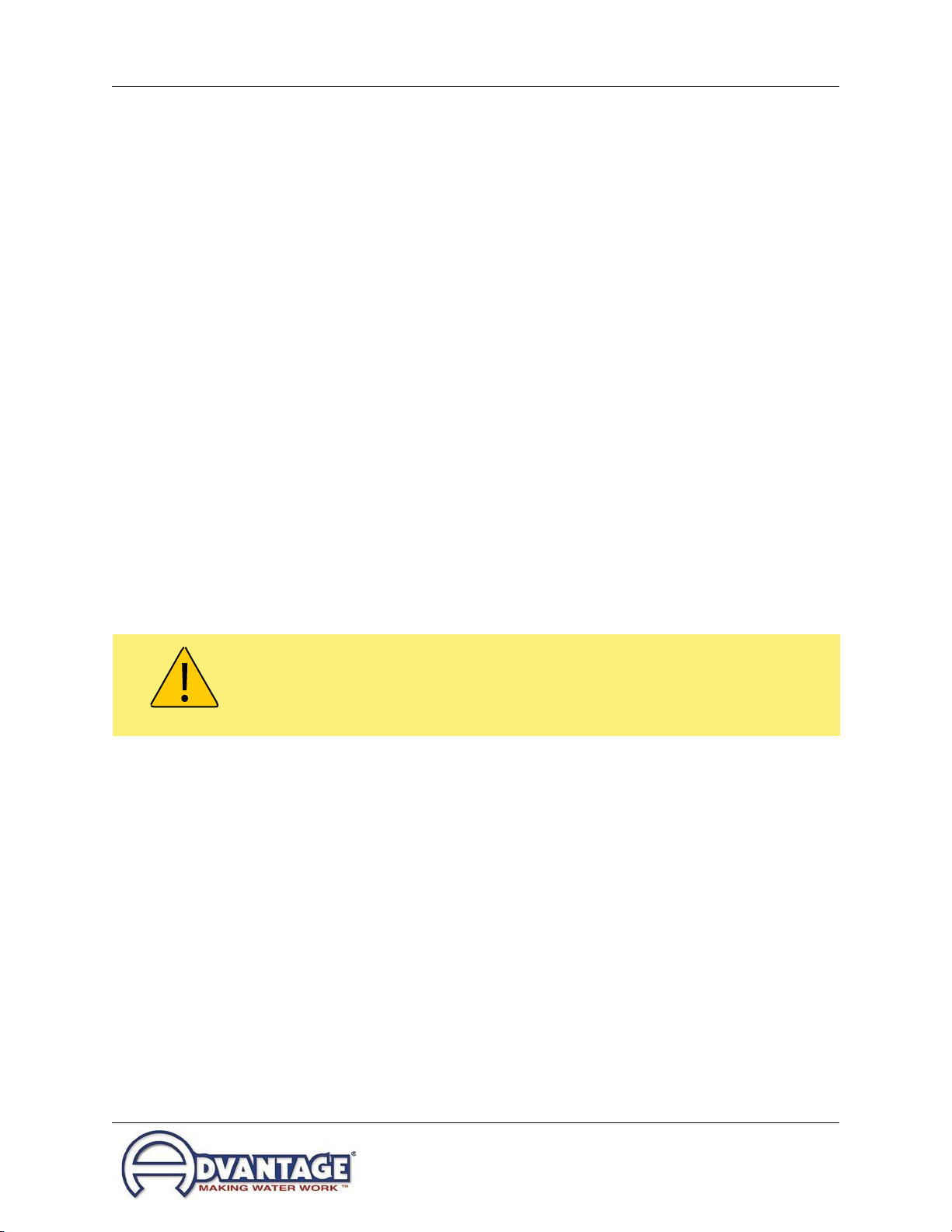
C. Chemical refrigerants (410A) is used in this unit. The refrigerant is sealed and tested in
a pressurized system however a system failure will release it. Refrigerant gas can
cause toxic fumes if exposed to fire. Install this unit in a well-ventilated area away from
open flames. Failure to follow these instructions may result in a hazardous condition.
Recover refrigerant to relieve pressure before opening the system. See nameplate for
refrigerant type. Do not use non-approved refrigerants or refrigerant substitutes.
D. Customers should implement a refrigerant management program to document the type
and quantity of refrigerant in each chiller. All refrigeration service technicians performing
work on this chiller must be licensed and certified.
E. When calling for assistance from the Manufacturer’s Service Department, it is important
to know the model and serial number of the particular unit. The model number includes
critical unit information which is helpful when troubleshooting operating difficulties. The
serial number allows the service team to locate manufacturing and testing records which
can have additional information relating to a particular unit.
1.2 SAFETY
A. It is important to become thoroughly familiar with this manual and the operating
characteristics of the unit.
B. It is the owner’s responsibility to ensure proper operator training, installation, operation,
and maintenance of the unit.
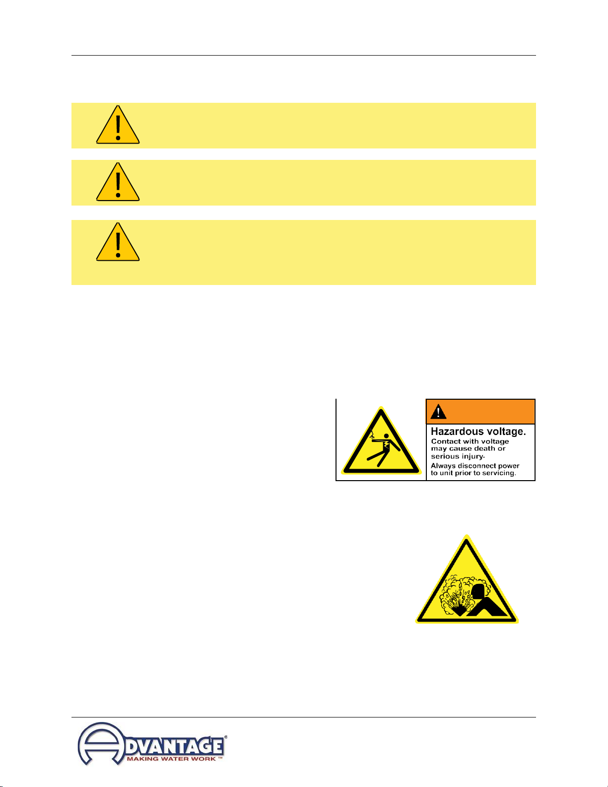
C. Observe all warning and safety placards applied to the chiller. Failure to observe all
warnings can result in serious injury or death to the operator and severemechanical
damage to the unit.
D. Observe all safety precautions during installation, startup and service of this equipment
due to the presence of high voltage and refrigerant charge. Only qualified personnel
should install, startup and service this equipment.

Portable Chiller: MGD-15W-ADV-02
Page: 9
ADVANTAGE ENGINEERING, INC.
525 East Stop 18 Road Greenwood, Indiana 46142
317-887-0729 Fax: 317-881-1277
Service Department Fax: 317-885-8683
Email: service@AdvantageEngineering.com
E. When working on this equipment, observe precautions in manual, literature, on tags,
stickers and labels located on the equipment. Wear work gloves and safety glasses.
F. Samples of Warning Labels applied to typical chillers.
1. Alerts users to the danger ofhigh
voltage.
2. Alerts users to the danger of the refrigeration system
under pressure. This symbol is seen on all chillers.
System should only be serviced by a licensed
technician.
WARNING: This equipment contains hazardous voltages that can cause severe injury or death.
Disconnect and lock out incoming power before installing or servicing the equipment.
WARNING
J5318-BF
WARNING:
This equipment contains refrigerant under pressure. Accidental release of refrigerant
under pressure can cause personal injury and or property damage. Exercise care while working
on or around this equipment.
WARNING: Vent all refrigerant relief valves in accordance to ANSI/ASHRAE Standard 15,
Safety Code for Mechanical Refrigeration. This equipment should be located within a well-
ventilated area. Inhalation of refrigerant can be hazardous to your health and the accumulation
of refrigerant within an enclosed space can displace oxygen and cause suffocation.

Portable Chiller: MGD-15W-ADV-02
Page: 10
ADVANTAGE ENGINEERING, INC.
525 East Stop 18 Road Greenwood, Indiana 46142
317-887-0729 Fax: 317-881-1277
Service Department Fax: 317-885-8683
Email: service@AdvantageEngineering.com
1.3 RECEIVING INSTRUCTIONS
A. Chillers are shipped skid mounted and wrapped in plastic prior to shipment. Checkthe
overall condition of the equipment prior to accepting delivery.
B. Check for visible damage and document any evident damage on the delivery receipt.
This unit has digital gauges. Tocheck the refrigerant pressure to be certain the system
charge is intact power must be applied to the unit. See the chart in section 8.2 forproper
pressure readings based on the ambient temperature and refrigerant type used in the
chiller. Shipping damage is the responsibility of the carrier.
C. In order to expedite payment for damages, should they occur, follow proper damaged
freight claim filing procedures with the carrier and keep detailed records. Take
photographs of any suspected damage.
1.4 EFFICIENCY
A. Long term efficiency of operation is largely determined by proper maintenance of the
mechanical parts of the unit and the water quality. The Manufacturer recommends
filtering the process water to prevent solids from plugging critical parts. TheManufacturer
highly recommends that the services of a qualified water treatment specialist be obtained
and their recommendations be followed. The Manufacturer accepts no responsibility for
inefficient operation, damage caused by foreign materials or failure to use adequate
water treatment.
1.5 CLEAN AIR ACT
A. This unit contains HFC-410A refrigerant.
B. It is unlawful for any person in the course of maintaining, servicing, repairing, ordisposing
of refrigeration equipment to knowingly vent or otherwise dispose of any substance used
as a refrigerant in the manner which permits such substance to enter theatmosphere.
C. Very small releases associated with good faith attempts to recapture, reclaim or
recycle such substance shall not be subject to the prohibition set forth in the preceding
paragraph.
D. Customers should implement a refrigerant management program to document the type
and quantity of refrigerant in each chiller. All refrigeration service technicians performing
work on this chiller must be licensed and certified.
E. Vent all refrigerant relief valves in accordance to ANSI/ASHRAE Standard 15.
WARNING: Vent all refrigerant relief valves in accordance to ANSI/ASHRAE Standard 15,
Safety Code for Mechanical Refrigeration. This equipment should be located within a well-
ventilated area. Inhalation of refrigerant can be hazardous to your health and the accumulation
of refrigerant within an enclosed space can displace oxygen and cause suffocation.

Portable Chiller: MGD-15W-ADV-02
Page: 11
ADVANTAGE ENGINEERING, INC.
525 East Stop 18 Road Greenwood, Indiana 46142
317-887-0729 Fax: 317-881-1277
Service Department Fax: 317-885-8683
Email: service@AdvantageEngineering.com
1.6 WATER TREATMENT
A. The use of untreated or improperly treated water in a portable chiller may result in
scaling, erosion, corrosion, algae or slime.
B. This unit needs to operate with propylene glycol since it is designed to operate at 14°F
leaving fluid temperature.
C. Advantage assumes no responsibility for equipment failures which result fromuntreated
or improperly treated water.
D. Do not use straight deionized or RO (reverse osmosis) water in this unit.
1.7 COMPONENTS
WARNING: Improper water treatment will void unit warranty.

Portable Chiller: MGD-15W-ADV-02
Page: 12
ADVANTAGE ENGINEERING, INC.
525 East Stop 18 Road Greenwood, Indiana 46142
317-887-0729 Fax: 317-881-1277
Service Department Fax: 317-885-8683
Email: service@AdvantageEngineering.com
2.0 INSTALLATION
2.1 General
2.2 Unit Location
2.3 Toand From Process Connections
2.4 Water cooled condenser
2.5 Electric connection

Portable Chiller: MGD-15W-ADV-02
Page: 13
ADVANTAGE ENGINEERING, INC.
525 East Stop 18 Road Greenwood, Indiana 46142
317-887-0729 Fax: 317-881-1277
Service Department Fax: 317-885-8683
Email: service@AdvantageEngineering.com
2.1 GENERAL
A. Chillers are shipped skid mounted and wrapped in plastic prior to shipment. Check the
overall condition of the equipment prior to accepting delivery. Check for visible damage
and document any evident damage on the delivery receipt. Shipping damage is the
responsibility of the carrier.
B. All process piping materials (such as hose, rigid piping, valves or filters) used in process
water piping circuitry must be rated for 10°F to 100°F temperature operating range and
70 PSI minimum pressure. Use appropriate piping materials.
C. All such materials must have the equivalent or larger diameter of the particular process
connection that length of process water piping is connected to.
2.2 UNIT LOCATION
A. Foundation. The chiller must be installed on a rigid and level mounting surface with
adequate strength to support the operating weight of the chiller including the weightof
water and attached piping.
This unit contains water/glycol when operating. It will also use a continuous flow
of plant water of 56°F while operating. Locate the chiller where an unforeseen
fluid leak will not cause damage to the surroundings or install the unit in such a
way that an unforeseen fluid leak will not damage its surroundings.
2.3 TO AND FROM PROCESS CONNECTIONS
A. Use appropriately rated hose or fluid piping to connect theprocess
piping going to your process to the “to process” connection on the
chiller. Needs to be rated for 14°F leaving fluid temperature.
B. Use appropriately rated hose or fluid piping to connect theprocess
piping coming back from your process to the “from process”
connection on the chiller. Needs to be rated for 14°F leaving fluid
temperature.
C. Install a high volume basket strainer in the From Process line with
isolation valves. A basket strainer or bag filter with a mesh screen
of 20-40 microns will protect the unit. A “wye” type strainer is
not recommended because it does not have adequate debris
holding capacity.
This label marks the
To Process connection
This label marks the
From Processconnection
Typical wye strainer -
Not recommended.
From Process

Portable Chiller: MGD-15W-ADV-02
Page: 14
ADVANTAGE ENGINEERING, INC.
525 East Stop 18 Road Greenwood, Indiana 46142
317-887-0729 Fax: 317-881-1277
Service Department Fax: 317-885-8683
Email: service@AdvantageEngineering.com
D. Process water piping should be designed to avoid excessive elbows and/or lengths of
pipe or hose. If using flexible hose avoid tight twists or curls and excessivelengths.
E. Valves and filters may be installed in the process water piping to facilitate service and
maintenance provided that such devices maintain the full inside diameter of the process
connection. If installed, all such devices must be open and clean during unit operation.
F. It is important to check all external process connections for leaks prior to starting the
unit. It is also important to check external connections, internal hose clamps and fitting
connections for leaks after servicing the unit.
G. Pressure relief valve may be installed between the overhead piping kit (backflow
prevention) and the process.

Portable Chiller: MGD-15W-ADV-02
Page: 15
ADVANTAGE ENGINEERING, INC.
525 East Stop 18 Road Greenwood, Indiana 46142
317-887-0729 Fax: 317-881-1277
Service Department Fax: 317-885-8683
Email: service@AdvantageEngineering.com
Condenser
Water In
2.4 WATER-COOLED CONDENSER
A. Connect the facility water supply to the “condenser water in” connection on the
unit. The facility water supply needs to be 54°F or cooler.
1. Required flow rate from facility at startup is 45 GPM.
2. Required flow rate from facility during design operation of
14°F leaving fluid is 14 GPM.
B. Connect the facility water system return or drain to the “condenser
water out” connection on the unit.
1. Note: Follow all local codes and regulations when
dumping to the plant’s sanitary or other drain.
This label marks the
Condenser Water In
connection
This label marks the
Condenser Water Out
connection
C. The pressure differential requirement between the condenser “water in” and the
condenser “water out” lines must be 30 psi minimum.
D. The installation of a strainer in the condenser “water in”
line is recommended. This removes solids from the water
supply and serves to protect the water saver (regulator)
valve.
E. The water regulator valve is normally factory set for
proper operation. When field adjustments are required,
turn the adjusting nut on the top of the valve counter
clockwise to raise the refrigerant pressure and clockwise
to lower the pressure. Adjustments should be made only
when the chiller is running at full load.
2.5 ELECTRICAL CONNECTION
Internal water saver regulator valve.
Condenser
Water out
WARNING: Do not connect the unit to a voltage supply not equal to the unit’s voltage
requirements as specified on the unit’s data plate. Use of incorrect voltage will void the unit’s
warranty and cause a significant hazard that may result in serious personal injury and unit
damage.
WARNING: Electric Shock Hazard. High Voltage is present in the electrical cabinet. Disconnect
power before servicing. Follow all facility lock-out/tag-out procedures.

Portable Chiller: MGD-15W-ADV-02
Page: 16
ADVANTAGE ENGINEERING, INC.
525 East Stop 18 Road Greenwood, Indiana 46142
317-887-0729 Fax: 317-881-1277
Service Department Fax: 317-885-8683
Email: service@AdvantageEngineering.com
A. STANDARD MODEL
1. All electrical wiring must comply with local codes.
2. Electrical power supply requirements for standard units
are identified on the equipment data tag. Determine
that the plant’s voltage supply is the same as the unit’s
voltage requirements, taking into account the SSCR
Rating.
3. A customer supplied, four conductor cable is
required for connection to a customer supplied fused
disconnecting means. The fused disconnecting
means shall be sized and installed according to the
unit’s power supply requirements and local electrical
codes. (Some custom units may include a fused or
non-fused disconnect switch. “Fused” may be fuses
on circuit breaker.)
4. Connect the four conductor power cable to the power
entry terminal block on the unit’s electrical panel.
Data tag.
5. Then connect the power cable to the fused disconnect switch. There is no power
entry hole into the electrical cabinet. This allows the matching of the entry hole
size and location to the customer supplied fittings.
6. A unit specific electrical drawing is shipped with the unit.
7. Voltage supplies must be within +/- 10% of the name plate voltage and must be
within 2% from leg to leg. Extreme voltage imbalance or using the wrong voltage
can damage your chiller and cause premature unit failure as well as a safetyrisk.
8. A proper ground is required for the unit.
B. CONTROL CIRCUIT WIRING
1. The unit’s will supply its internal control circuit is single phase 115 volt 60Hz or
single phase 110volt 50 Hz. The voltage and hertz are dependent on the hertz
of the connected grid.
2. The control circuit is supplied by the factory installed transformer. A control circuit
fuse is provided.
C. GENERAL
1. Make certain all ground connections to the unit are properly affixed.
2. Make certain power conductor, disconnecting means, and fusing are properly
sized according to the unit’s power supply requirements.
3. Follow all local and national codes.
4. Make certain that all owner and factory wire connections are tight before applying
power to the unit.

Portable Chiller: MGD-15W-ADV-02
Page: 17
ADVANTAGE ENGINEERING, INC.
525 East Stop 18 Road Greenwood, Indiana 46142
317-887-0729 Fax: 317-881-1277
Service Department Fax: 317-885-8683
Email: service@AdvantageEngineering.com
D. EMO Interlock
1. To place the chiller EMO in isolation, connect TB26 to TB28 and connect TB27
to TB29 as shown below.
2. To place the EMO in series interlock with external EMO’s connect an external
24VDC to TB26, EMO’d 24VDC to TB25 and external ground TB27.

Page: 18
ADVANTAGE ENGINEERING, INC.
525 East Stop 18 Road Greenwood, Indiana 46142
317-887-0729 Fax: 317-881-1277
Service Department Fax: 317-885-8683
Email: service@AdvantageEngineering.com
Portable Chiller: MGD-15W-ADV-02
WARNING: Check that all owner and factory electrical connections are tight before starting.
Disconnect power before servicing. Follow all facility lock-out tag-out procedures.

Portable Chiller: MGD-15W-ADV-02
Page: 19
ADVANTAGE ENGINEERING, INC.
525 East Stop 18 Road Greenwood, Indiana 46142
317-887-0729 Fax: 317-881-1277
Service Department Fax: 317-885-8683
Email: service@AdvantageEngineering.com
3.0 OPERATIONS
3.1 General
3.2 Start Up/Operations Procedure
3.3 Instrument : Startup & Operation
3.4 Instrument : Main Menu
3.5 Instrument : Setpoints Menu
3.6 Instrument : Utilities Menu
3.7 Instrument : Network Menu
3.8 Instrument : Options Menu
3.9 Instrument : Machine Menu
3.10 Shut Down procedure

Portable Chiller: MGD-15W-ADV-02
Page: 20
ADVANTAGE ENGINEERING, INC.
525 East Stop 18 Road Greenwood, Indiana 46142
317-887-0729 Fax: 317-881-1277
Service Department Fax: 317-885-8683
Email: service@AdvantageEngineering.com
3.1 GENERAL
A. Failure to follow the factory required operations procedure may adversely affect theunit’s
ability to adequately control process temperature and may create a hazardous operating
condition which may result in serious operator injury and/or unit damage.
B. The OPERATIONS segment of this manual is divided into the following sections:
3.2 Startup/operations - follow this segment to start the unit after the initial
installation to the process system or to restart the unit after reinstallation to the
same or different process system. This section includes information on system
fill, electric motor phasing (motor rotation) and process flow adjustments.
3.3 Chiller Control - follow this segment to start up and operate the chiller control.
This section includes information on setpoint selection and adjustment, and
feature explanations.
3.4 Shut down procedure - follow this segment to shut down the unit. This segment
includes information on system shut down, electrical power supply precautions,
and disconnection from system.
3.2 START UP / OPERATION PROCEDURE
A. System Fill
1. An inhibited propylene glycol mixture must be used in the system. You will
need to manual fill the system at startup using the fill port located on the unit.
Use a minimum of a 40% ratio. See section 8 of this manual for more
information.
2. The unit has an internal reservoir which must be filled and maintained for proper
operation. The unit has a level switch mounted at the proper water level in the
reservoir.
WARNING: Follow all Factory operations procedures. Failure to do so may create a hazardous
operating condition which may result in serious operator injury and/or unit damage.
NOTICE: See Section 8 of this Manual if using a water & glycol fluid mixture.
Table of contents
Other Advantage Chiller manuals
Popular Chiller manuals by other brands

REMKO
REMKO RVS Series Operating & installation instructions

ATC
ATC A01 Installation, operation & service manual

Carrier
Carrier AQUASNAP MPW015-045 Operation and service manual

Carrier
Carrier 30RBM 160 Installation, operation and maintenance instructions

National Lab
National Lab PCGE Series Operating and maintenance manual

Marco
Marco FRIIA HC quick start guide