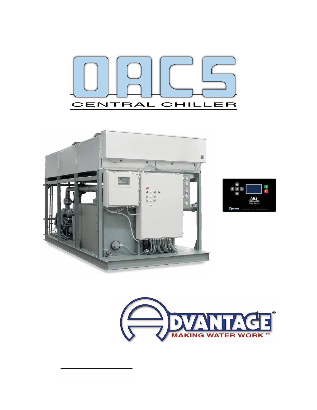
OACS Central Chillers : with MG Series Control Instrument
Page: 8
ADVANTAGE ENGINEERING, INC.
525 East Stop 18 Road Greenwood, Indiana 46142
317-887-0729 Fax: 317-881-1277
Service Department Fax: 317-885-8683
1.1 INTRODUCTION
A. This manual covers OACS central chillers from 5 to 210 tons (17.2 to 717.4 kW) of
cooling capacity using the Advantage MG microprocessor control instrument and
xeddisplacementscrollcompressorsanddigitalscrollcompressors.Thestandard
uidoperatingtemperaturerangeforthischilleris20°Fto80°FforunitsusingR410A
refrigerant. Units using other refrigerants have different standard operating ranges. Units
operatingbelow48°Fuidrequiretheuseofawater/propyleneglycoltopreventfreezing.
Customized units may have different operating ranges. Consult the factory if you have
questions about the operating range of your chiller.
B. The intent of this manual is to serve as a guide in the installation, operation and
maintenance of your chiller. Improper installation can lead to equipment damage
and poor performance. Failure to follow the installation, operation and maintenance
instructions may result in damage to the unit that is not covered under the limited
warranty. This manual is for standard products. The information contained in this manual
is intended to be general in nature. The information is typical only and may not represent
the actual unit purchased.
C. Chemical refrigerants are used in this unit. The refrigerant is sealed and tested in a
pressurized system however a system failure will release it. Refrigerant gas can cause
toxicfumesifexposedtore.Installthisunitinawell-ventilatedareaawayfromopen
ames.Failuretofollowtheseinstructionsmayresultinahazardouscondition.Recover
refrigerant to relieve pressure before opening the system. See nameplate for refrigerant
type. Do not use non-approved refrigerants or refrigerant substitutes.
D. Customers should implement a refrigerant management program to document the type
and quantity of refrigerant in each chiller. All refrigeration service technicians performing
workonthischillermustbelicensedandcertied.
E. WhencallingforassistancefromtheManufacturer’sServiceDepartment,itisimportant
to know the model and serial number of the particular unit. The model number includes
criticalunitinformationwhichishelpfulwhentroubleshootingoperatingdifculties.The
serial number allows the service team to locate manufacturing and testing records which
can have additional information relating to a particular unit.
F. If the chiller is installed in an environment where ambient temperatures could be under
35°F and/or if the unit operating set point will be 48°F or lower, a glycol and water
solution must be used instead of water. See section 8.1 for glycol ratio recommendations
and proper unit setting.
1.2 SAFETY
A. It is important to become thoroughly familiar with this manual and the operating
characteristics of the unit.
B. Itistheowner’sresponsibilitytoassureproperoperatortraining,installation,operation,
and maintenance of the unit.
C. Observe all warning and safety placards applied to the chiller. Failure to observe all
warnings can result in serious injury or death to the operator and severe mechanical
damage to the unit.