AIMB-281 User Manual viii
*Use external VGA card to perform this test, DO NOT use on-board internal VGA.
Ordering Information
*() not populated on MP version.
Product Warranty (2 years)
Advantech warrants the original purchaser that all its products will be free from
defects in materials and workmanship for two years from the date of purchase.
This warranty does not apply to any products that have been repaired or altered by
persons other than the repair personnel authorized by Advantech, or that have been
subject to misuse, abuse, accident, or improper installation. Advantech assumes no
liability under the terms of this warranty as a consequence of such events.
Because of Advantech’s high quality-control standards and rigorous testing, most
customers never need to use our repair service. If an Advantech product is defective,
it will be repaired or replaced at no charge during the warranty period. For out-of-war-
ranty repairs, customers are billed according to the cost of replacement materials,
service time, and freight. Please consult your dealer for more details.
If you believe your product to be defective, please follow the steps outlined below.
1. Collect all information about the problem encountered. (For example, CPU
speed, Advantech products used, other hardware and software used, etc.) Note
anything abnormal and record any onscreen messages displayed when the
problem occurs.
2. Call your dealer and describe the problem. Please have your manual, product,
and any relevant information readily available.
3. If your product is diagnosed as defective, obtain an RMA (return merchandise
authorization) number from your dealer. This allows us to process your return
more quickly.
4. Carefully pack the defective product, a completed Repair and Replacement
Order card, and proof of purchase date (such as a photocopy of your sales
receipt) in a shippable container. Products returned without a proof of purchase
date are not eligible for warranty service.
5. Write the RMA number clearly on the outside of the package, then ship the
package prepaid to your dealer.
Memory No. Test Procedure Result
MEM-01
System can boot up Pass
Check if BIOS can detect correct capacity and speed Pass
System can power on/off x 10 Pass
Run Memtest86 for 3 loops Pass
Run Prime95 for 1 hour Pass
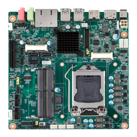
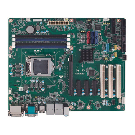
Part Number Chipset CRT DVI LVDS GbE LAN COM
AIMB-281G2-00A1E H61 Yes Yes Yes 2 6
