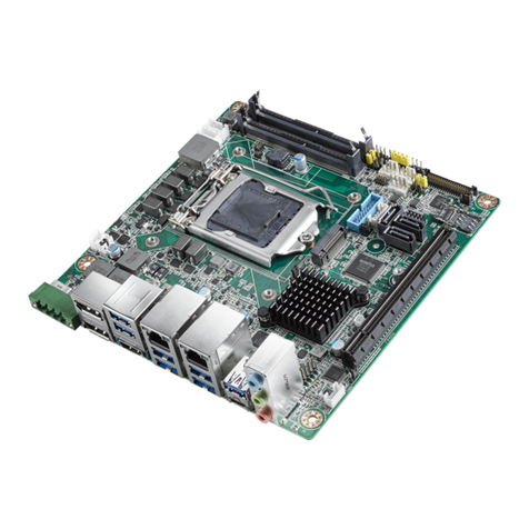
v SIMB-M22 User Manual
Contents
Chapter 1 Product Overview ................................1
1.1 Specifications Summary............................................................................ 2
1.1.1 System .......................................................................................... 2
1.1.2 Memory ......................................................................................... 2
1.1.3 Chipset.......................................................................................... 2
1.1.4 BIOS ............................................................................................. 4
1.1.5 Internal Connector ........................................................................ 4
1.1.6 Front I/O........................................................................................ 5
1.1.7 Power............................................................................................ 6
1.1.8 LED Indicator ................................................................................ 6
1.1.9 Expansion Slot .............................................................................. 6
1.1.10 Accessory ..................................................................................... 7
1.2 Block Diagram........................................................................................... 7
Figure 1.1 Block Diagram ............................................................ 7
Chapter 2 Product Introduction ...........................9
2.1 Before you proceed................................................................................. 10
2.2 Motherboard overview............................................................................. 10
2.2.1 Placement Direction.................................................................... 10
2.2.2 Screw Holes................................................................................ 11
2.3 Motherboard Layout ................................................................................ 12
Figure 2.1 Board Layout ............................................................ 12
Table 2.1: Slots.......................................................................... 12
Table 2.2: Jumpers.................................................................... 12
Table 2.3: Rear IO ..................................................................... 13
2.4 Central Processing Unit (CPU) ............................................................... 13
2.4.1 Connect the CPU Fan cable to the CPU_FAN connector on the
motherboard................................................................................ 13
2.4.2 Connect the CPU Fan Cable ...................................................... 14
2.5 System Memory ...................................................................................... 15
2.5.1 DIMM Sockets Location .............................................................. 15
2.5.2 Memory Configurations............................................................... 15
2.5.3 Installing a DDR3 DIMM ............................................................. 16
2.5.4 Removing a DDR3 DIMM ........................................................... 17
2.6 Expansion Slots ...................................................................................... 17
2.6.1 Installing an Expansion Card ...................................................... 17
2.6.2 Configuring an Expansion Card .................................................. 18
2.6.3 Standard Interrupt Assignments ................................................. 18
2.7 Jumpers .................................................................................................. 18
2.7.1 Clear CMOS (CMOS1) ............................................................... 18
2.7.2 COM3 RI/+5V/+12V Selection (JSETCOM3).............................. 19
2.7.3 COM4 RI/+5V/+12V Selection (JSETCOM4).............................. 20
2.8 Connectors.............................................................................................. 20
2.8.1 Rear Panel Connectors............................................................... 20
Figure 2.2 Rear Panel Connectors ............................................ 20
2.8.2 Front Panel Audio Connector (AAFP)......................................... 22
2.8.3 ATX Power Connector (ATXPWR) ............................................. 22
2.8.4 AT/ATX Mode Select (PSON1)................................................... 23
2.8.5 LCD POWER (VDDSAFE) (JBL3) .............................................. 23
2.8.6 Serial Port Connector (COM3, COM4) ....................................... 24
2.8.7 System Panel & Speaker (JFP1 + JFP2).................................... 24
2.8.8 Power LED & Keylock (JFP3) ..................................................... 25
2.8.9 Inverter PWR (JBL1)................................................................... 25

