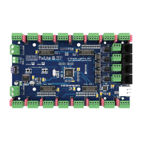
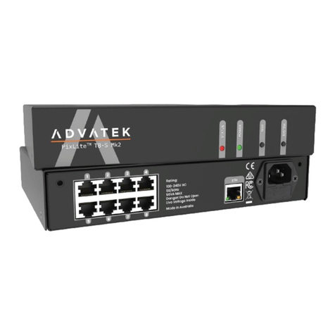
Advantek PixLite E4-S Mk3 User manual

www.advateklights.com PixLite E4-S Mk3 User Manual V20220819
PixLite E4-S Mk3 User Manual

- 2 -
www.advateklights.com PixLite E4-S Mk3 User Manual V20220819
1 - Table of Contents
1 - Table of Contents 2
2 - Introduction 4
2.1 - Management &Configuration 4
3 - Safety Notes 5
4 - Physical Installation 6
4.1 - Wall Mount 6
4.2 - DIN Rail Mount 7
5 - Electrical Connections 10
5.1 - Supplying Power 10
5.2 - Control Data 11
5.3 - Connecting Pixel LEDs 11
5.4 - Expanded Mode 12
5.5 - Aux Port 13
6 - Network Configuration 15
6.1 - Network Layout Options 15
6.2 - IGMPSnooping 16
6.3 - IPAddressing 16
6.3.1 - DHCP 16
6.3.2 - AutoIP 16
6.3.3 - Static IP 17
6.3.4 - Factory IPAddress 17
7 - Operation 19
7.1 - Start-up 19
7.2 - Sending Ethernet Data 19
7.3 - Pixel Outputs 19
7.4 - Button Actions 20
7.5 - Hardware Test Pattern 20
7.6 - Operating Refresh Rates 21
7.7 - sACNPriorities 21
7.8 - Advatek SHOWTime 22

- 3 -
www.advateklights.com PixLite E4-S Mk3 User Manual V20220819
8 - Firmware Updates 23
8.1 - Updating via the Management Interface 23
9 - Specifications 24
9.1 - Operating Specifications 24
9.1.1 - Power 24
9.1.2 - Thermal 24
9.2 - Physical Specifications 24
9.3 - Electrical Fault Protection 25
10 - Troubleshooting 26
10.1 - LEDCodes 26
10.2 - Statistical Monitoring 27
10.3 - Solutions for Common Issues 28
10.4 - Other Issues 28
10.5 - Reset to Factory Defaults 28
11 - Disclaimer 30

- 4 -
www.advateklights.com PixLite E4-S Mk3 User Manual V20220819
2 - Introduction
This is the user manual for the PixLite E4-S Mk3 pixel controller. The PixLite E4-S Mk3 is a
powerful pixel LED controller built upon Advatek’s 3rd generation PixLite Mk3 processor.
At its core, the controller converts sACN, Art-Net and DMX512 protocols from lighting
consoles, media servers or computer lighting software into various pixel
LEDprotocols. With the PixLite Mk3 processor, the PixLite E4-S Mk3 brings powerful
operational functionality and advanced management platforms.
2.1 - Management &Configuration
This manual covers physical aspects of the PixLite E4- S Mk3 controller and its
essential setup steps only. Detailed information about its configuration options can
be found in the ‘PixLite Mk3 Management Guide’.
Configuration, management, and monitoring of this device can be performed via the
web-based Management Interface. To access the interface, either open any web
browser and navigate to the IP address of the device, or use Advatek Assistant 3,
which can be downloaded here:
https://www.advateklights.com/advatek-assistant-3
Figure 1: Management Interface Home Page
Other manuals and the PixLite Mk3 Management Guide may be downloaded from:
www.advateklights.com/downloads

- 5 -
www.advateklights.com PixLite E4-S Mk3 User Manual V20220819
3 - Safety Notes
This LEDpixel controller should be installed by someone with proper technical
knowledge only. Installation of the device should not be attempted without such
knowledge.
The pixel output connectors shall be used for pixel output connection only.
Completely disconnect the supply source during abnormal operation and before
making any other connections to the device.
Specification and certification markings are located on the side of the device.

- 6 -
www.advateklights.com PixLite E4-S Mk3 User Manual V20220819
4 - Physical Installation
4.1 - Wall Mount
Assemble the unit onto the wall / ceiling using four screws of a type suitable for the
mounting surface (not supplied). The screws should be a pan head type, 3mm in
thread diameter and at least 15mm long, as shown in Figure 2 below.
Figure 2: Controller Assembled to Wall

- 7 -
www.advateklights.com PixLite E4-S Mk3 User Manual V20220819
4.2 - DIN Rail Mount
The controller can be mounted to a DIN rail using the optional mounting kit (part
number MNT0101).
1. Align the controller's mounting holes with the outermost mounting holes on
each bracket. Using the four supplied M3, 12mm long screws, assemble the
controller to the mounting brackets, as shown in Figure 3 below.
Figure 3: Controller Assembled to Bracket

- 10 -
www.advateklights.com PixLite E4-S Mk3 User Manual V20220819
5 - Electrical Connections
5.1 - Supplying Power
Power is applied to the PixLite E4-S Mk3 via the small pluggable screw terminal
connector. The screws should be loosened for wire insertion and then tightened
again, providing a highly robust and secure connection. Polarity for the connector is
clearly marked on the lid (“+” & “-”), as shown in Figure 6 below. The type of wire
required for supply connection is 1.0mm2, 16AWG, VW-1.
Refer to Section 9.1 for operating specifications for powering this device.
Figure 6: Location of Power Input
Pixels that are connected to the PixLite E4-S Mk3 cannot be powered through the
device itself; any pixels connected must have their power sourced separately from a
power supply instead. If multiple power supplies are in use, then the DC ground (also
known as "negative") terminals of each power supply must be connected together, in
order to achieve a common DC ground.
Advatek recommends fusing each positive line that is used to power the pixels, using
an in-line fast blow fuse.

- 11 -
www.advateklights.com PixLite E4-S Mk3 User Manual V20220819
5.2 - Control Data
Ethernet data is connected via a standard network cable into the RJ45 Ethernet port
located on the front side of the unit, as shown in Figure 7 below.
Figure 7: Position of Ethernet
5.3 - Connecting Pixel LEDs
A high level wiring diagram for connecting pixel LEDs to a PixLite E4-S Mk3 is shown in
Figure 8 below. Refer to Section 7.3 for the specific capacity of a pixel output.
Figure 8: Pixel Set up
The pixel lights are connected directly via the 4 pluggable screw terminal connectors
on the rear of the unit. Each connector is labelled with its output channel number (1-
4) which is clearly marked on the top surface. Simply wire your lights into each screw
terminal and then plug them into the mating sockets.
The cable length between the output and the first pixel should not exceed 15m.

- 12 -
www.advateklights.com PixLite E4-S Mk3 User Manual V20220819
Figure 9 shows the pin-out of the pixel output connectors.
Figure 9: Pixel Output Pinout - Expanded Mode Disabled
5.4 - Expanded Mode
If your pixels do not have a clock line, you may optionally activate expanded mode on
the controller, via the Management Interface. In expanded mode, the clock lines are
used as data lines instead. This means the controller effectively has twice as many
pixel outputs (8), but half as many pixels per output can be run.
Compared to pixels with a clock line, pixels that only use a data line have the
potential to lower the maximum achievable refresh rate in a pixel system. If a pixel
system is using data-only pixels, then the refresh rates will typically be improved by
using expanded mode. Enabling expanded mode allows for twice as many data
outputs, so the same number of pixels can be spread out over these outputs,
resulting in a large improvement to refresh rate. This becomes more important as the
number of pixels per output increases.
Mapping of these pixel outputs in the Management Interface will appear as follows:
Expanded Mode Enabled
Management Interface Output Pixel Output Pin Name
1 1 Clock
2 1 Data
3 2 Clock
4 2 Data
5 3 Clock
6 3 Data
7 4 Clock
8 4 Data

- 13 -
www.advateklights.com PixLite E4-S Mk3 User Manual V20220819
Expanded Mode Disabled
Management Interface Output Pixel Output Pin Name
1 1 Data
2 2 Data
3 3 Data
4 4 Data
The pinout for expanded mode is shown in Figure 10 below.
Figure 10: Pixel Output Pinout - Expanded Mode Enabled
5.5 - Aux Port
The PixLite E4-S Mk3 has 1 multipurpose auxiliary (Aux) port that can be used for
DMX512 communication using RS485 electrical signals. It is capable of outputting
DMX512 to other devices or receiving DMX512 from another source.
Configure the Aux port to DMX512 Output to allow conversion of a single universe of
incoming sACN or Art-Net data to the DMX512 protocol. This then allows any DMX512
device(s) to be connected to this port and effectively be controllable over Ethernet.
Configure the Aux port to DMX512 Input to allow the PixLite to be driven by an external
source of DMX512 control. Whilst this is limited to only a single universe of data, the
PixLite can use DMX512 as its source of pixel data for situations where a DMX512
control system is required to be used instead of Ethernet-based data.
The Aux port connector is located on the front side of the unit as shown in Figure 11
below.

- 14 -
www.advateklights.com PixLite E4-S Mk3 User Manual V20220819
Figure 11: Location and Pinout of the Aux Port

- 15 -
www.advateklights.com PixLite E4-S Mk3 User Manual V20220819
6 - Network Configuration
6.1 - Network Layout Options
Figure 12: Network Layout using a Switch and Router
Figure 12 shows a typical network topology for the PixLite E4-S Mk3.
The Lighting Control Device could be any source of Ethernet data - e.g. desktop PC,
laptop, lighting console, or media server.
Having a router on the network is not mandatory but is useful for IP address
management with DHCP (see Section 6.3.1).
Figure 13: Network Layout Without a Switch/Router
The controller can alternatively be connected directly to the host machine, as shown
in Figure 13. A crossover cable is not required in this case, but it may be used if
desired.

- 16 -
www.advateklights.com PixLite E4-S Mk3 User Manual V20220819
The controller(s) can be integrated straight into any pre-existing LAN such as your
media, home or office network, the above diagrams are only provided as examples.
6.2 - IGMPSnooping
Installations using multicast sACN will benefit from the use of IGMP Snooping enabled
network equipment when there are more multicast universes on the network than
any one PixLite is using. If there are more than 24 universes of multicast sACN on the
network then IGMP Snooping is mandatory.
Note: "E" Series devices are not equipped with a Universe Data Hardware Firewall,
which many other PixLite Mk3 devices have. This feature removes the need for IGMP
Snooping. This means that operation of the PixLite E4-S Mk3 in the situation described
above will require IGMPSnooping, as there is no hardware firewall in place.
6.3 - IPAddressing
6.3.1 - DHCP
Routers typically have an internal DHCP server, which means they can assign an IP
address to a connected device, if requested.
DHCP is always enabled by default on this device, so it can immediately connect to
any existing network with a router / DHCP Server. If the controller is in DHCP mode and
is not assigned an IP address by a DHCP server, it will assign itself an IP address with
Automatic IP Addressing, as explained in Section 6.3.2 below.
6.3.2 - AutoIP
When this device has DHCP enabled (factory default), there is also functionality for it
to be operational on networks without a DHCP server, via the AutoIP mechanism.
When no DHCP address is being offered to this device it will generate a random IP
address in the range of 169.254.X.Y that does not conflict with any other devices on
the network. The benefit of AutoIP is that communication can happen between the
device and any other compatible network device, without the need for a DHCP server
or pre-configured Static IP addressing.

- 17 -
www.advateklights.com PixLite E4-S Mk3 User Manual V20220819
This then means that connecting a PixLite E4-S Mk3 directly to a PC typically does not
require any IP address configuration - communication will be possible because both
devices would generate their own valid AutoIP.
While the device has an AutoIP address in use, it continues searching for a DHCP
address in the background. If one becomes available, it will switch to the DHCP
address instead of the AutoIP.
6.3.3 - Static IP
In many typical lighting networks that this device would operate in, it’s common for
the installer to manually manage a set of IP addresses, instead of relying on DHCP or
AutoIP. This is referred to as static network addressing.
When allocating a static address, the IP address and the subnet mask both define the
subnet that the device is operating on. You need to ensure that other devices that
need to communicate with this device are on the same subnet. Therefore they should
have the same subnet mask and a similar but unique IP address.
When setting static network settings, the Gateway address can be set to 0.0.0.0 if it is
not required. If communication between the device and other VLANs is required, the
Gateway address should be configured and will typically be the IP address of the
router.
Note: You may not assign a static IP address equal to the Factory IP address
(192.168.0.50).
6.3.4 - Factory IPAddress
When you are not sure what IP address the device is using, you can force it to use a
known IP address (referred to as the Factory IP).
To activate the Factory IP and establish communication with the device:
1. While the controller is running, hold down the "Reset" button for 3 seconds.
2. Release the button.
3. The controller will immediately restart its application with the following
factory default network settings:
IPAddress: 192.168.0.50
Subnet Mask: 255.255.255.0
Gateway Address: 0.0.0.0

- 18 -
www.advateklights.com PixLite E4-S Mk3 User Manual V20220819
4. Configure your PC with compatible network settings. If you are not sure, you
can try the following example settings:
IPAddress: 192.168.0.49
Subnet Mask: 255.255.255.0
Gateway Address: 0.0.0.0
5. You should now be able to access the device’s Management Interface by
manually browsing to 192.168.0.50 in your web browser, or by using Advatek
Assistant 3.
After establishing a connection to the device, make sure to configure the IP address
settings for future communication and save the configuration.
Note: The Factory IP is only a temporary setting used to regain connectivity to the
device. When the device is reset (powered off and on again), the IP address settings
will revert to what is configured in the device.

- 19 -
www.advateklights.com PixLite E4-S Mk3 User Manual V20220819
7 - Operation
7.1 - Start-up
Upon applying power, the controller will quickly begin outputting data to the pixels. If
no data is being sent to the controller, then the pixels will remain turned off until valid
data is received. During live mode, the multi color status LEDwill be flashing green to
indicate the controller is running and outputting any received data to the pixels.
7.2 - Sending Ethernet Data
Input data is sent from the control PC/server/lighting console to the controller via
Ethernet using a “DMX over IP” protocol such as sACN (E1.31) or Art-Net. This device will
accept Art-Net or sACN data on either Ethernet port.
Sync modes are supported for both Art-Net and sACN. To learn more, refer to the
technical note on synchronous mode here:
www.advateklights.com/knowledge-base
Details of incoming and outgoing packets can be viewed in the Management
Interface.
7.3 - Pixel Outputs
Each of the 4 pixel outputs on the PixLite E4-S Mk3 can drive up to 6 universes of data.
This allows for a total of up to 24 universes of pixel data to be driven out of the one
controller. The number of pixels that can be driven per pixel output will depend on the
configuration, as shown in the table below.
Expanded Mode Disabled Enabled
Color Type RGB RGBW RGB RGBW
Max Pixels per Pixel Output 1,020 768 510 384
Max Total Pixels 4,080 3,072 4,080 3,072
The PixLite must be configured before it can correctly output pixel data. Refer to the
PixLite Mk3 Management Guide for how to configure and patch your pixel outputs.

- 20 -
www.advateklights.com PixLite E4-S Mk3 User Manual V20220819
7.4 - Button Actions
The 'Test' and 'Reset' buttons can be used to perform various operations, as listed
below.
Action Test Button Reset Button
Toggle Test Mode On/Off Press for >3 seconds while
the application is running -
Cycle the Test Modes Press whilst in test mode -
Hardware Reset - Press momentarily
Factory Reset - Press for >10 seconds
Factory IP - Press for 3 seconds
7.5 - Hardware Test Pattern
The controller features a built-in test pattern to assist in troubleshooting during an
installation. To put the controller into this mode, press and hold the ‘TEST’ button for 3
seconds (after the controller is already running) or turn it on remotely using its
Management Interface.
The controller will then enter the test pattern mode, where different test patterns are
available as described in the table below. The controller will display the test pattern
on all pixels on each of the pixel outputs and the Aux DMX512 output (if enabled)
simultaneously. Pressing the 'TEST' button while in test mode will move through each
of the patterns successively in one continuous loop.
Test Operation
Color Cycle
Outputs will cycle automatically through the red, green,
blue and white colors at fixed intervals.
Pressing the TEST button moves to the next mode.
Red Solid Red
Green Solid Green
Blue Solid Blue
White Solid White
Color Fade
Outputs will slowly move through a continuous color fade.
Pressing the TEST button will loop back to the original color
cycle test mode.
Table of contents
Other Advantek Controllers manuals
Popular Controllers manuals by other brands
Samson
Samson 42-34 Mounting and operating instructions
elsner elektronik
elsner elektronik KNX eTR MultiTouch installation instructions

Flomatic
Flomatic FCEL operating manual

ITOH DENKI
ITOH DENKI POWER MOLLER HBM-604BN Technical document
Illumi Led
Illumi Led 5M5050RGB instructions

Honeywell
Honeywell L482A installation instructions


