7
INV250 / INV350 / INV50008.2013
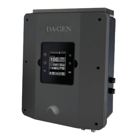
5.3 LED-Display
During normal operation, the PV generators produce a voltage
when sucient daylight or sunlight is present. If this voltage at
a certain level and corresponding time period is applied to the
inverter, the inverter starts to feed into the grid. The inverter is
equipped with an LED, which gives information on the operating
status and causes for non-operation.
Feeding Operation:
Depending on the power the blink frequency is increasing. The
following blink frequencies show percentages as a function of
the device power:
0% to 3% LED 0.5 sec.„ON“ 2 sec.„OFF“
3% to 30% LED 0.5 sec„ON“ 1 sec.„OFF“
30% to 60% LED 0.5 sec„ON“ 0.5 sec„OFF“
60% to 85% LED 0.5 sec„ON“ 0.2 sec„OFF“
85% to 100% LED continuously„ON“
Non-feeding Operation:
When in non-feeding operation, the LED indicates certain
output stages, which are described hereafter. These can be used
to troubleshoot the inverter in case of malfunction. Each stage
indication starts with the following sequence:
Sequence starts: 2 sec„ON“, 0.5 sec “OFF“
Output Stages:
Synchronization running:
LED 1sec„ON“ 0.5sec„OFF“, one pulse
AC Voltage not in tolerance range:
LED 1sec„ON“ 0.5sec„OFF“, two pulses
DC Voltage not in tolerance range:
LED 1sec„ON“ 0.5sec„OFF“, three pulses
AC and DC Voltage not in tolerance range:
LED 1sec„ON“ 0.5 sec„OFF“, four pulses
Internal over-temperature:
LED 1sec„ON“ 0.5 sec„OFF“, ve pulses
5.4 Protection Concepts
The following monitoring concepts and protection plans are
included in the AEconversion scope of devices:
• Surge / varistors to protect the power semiconductor
• temperature monitoring
• EMC lters to protect the inverter against high-frequency
power disturbances
• varistors to earth on the mains side to protect the inverter
against surge voltages
• BISI (Bi-directional security interface ) network monitoring
for personal protection and to prevent islanding according
to VDE0126-1-1 / VDE AR-N 4105
5.5 Network and System Protection
According to the VDE-AR-N 4105, the last ve fault conditions
of the network and system protection as well as the set action
values and times must be readable. For the device versions
without a communication interface and with integrated light
conductors, the data output is realized through the LED.
For devices with a communication interface, the data is
additionally available via the integrated interface.
Activation of the output via light conductors:
• turn o AC
• LED signals the start of the output sequence through 5
seconds„ON“
• LED puts out the data as a pulse pattern (duration 50 sec)
• LED signals the end of the output sequence through 5
seconds„ON“
• LED turns to normal mode signaling
The LED output sequence must be recorded via video
(smartphone, digital camera, etc.) with a resolution of
680x480DPI. This video is then analyzed using the computer
software. The software is included on the supplied CD. After a
successful analysis of the video, the set values are displayed in
plain text. When recording, make sure that a few seconds each
of the start and end of the output sequence are recorded. The
position of the LED on the screen surface must always be kept
in the same position. Please note further instructions when
running the software.
Additional option for versions with communication interface:
• Establish data communication between PC and Inverter
• Load AEsolar software
• Check device via the corresponding menu item
6.0 Operating Conditions
The selection of the PV generator is of central importance to the
design of a PV system. It is highly relevant that the PV module
ts to the inverter.
6.1 Dimensioning of the PV-Generators
The number of PV modules connected in series must be
chosen so that the output voltage of the PV generator, even in
extreme outdoor temperatures does not exceeded the allowed
input voltage range of the inverter. In Central Europe, module
temperatures between -15°C to +70°C should be assumed.
Depending on the installation of the generators and the
geographical location, temperatures of +60°C or +70°C are used
in the stress voltage calculation. Please note the temperature
coecient of PV modules. The following criteria must be met for
the voltage of the PV generator:
Uo (-15 ° C) <max. Input voltage
45 V and -15°C for INV250
60 V and -15°C for INV350
90 V and -15°C for INV500


